1993 CHEVROLET PLYMOUTH ACCLAIM low oil pressure
[x] Cancel search: low oil pressurePage 1570 of 2438
REMOVE ALL SHIMS BEFORE REASSEM-
BLING ENGINE ALTERNATIVE METHOD Ð With the weight of
the crankshaft being supported by a jack under the
counterweight adjacent to the bearing being checked. (3) Place a piece of Plastigage across the entire
width of the bearing shell in the cap approximately
6.35 mm (1/4 inch) off center and away from the oil
holes (Fig. 2). (In addition, suspect areas can be
checked by placing the Plastigage in the suspect area).
Torque the bearing cap bolts of the bearing being
checked to the proper specifications. (4) Remove the bearing cap and compare the width
of the flattened Plastigage (Fig. 3) with the metric scale
provided on the package. Locate the band closest to the
same width. This band shows the amount of clearance
in thousandths of a millimeter. Differences in readings
between the ends indicate the amount of taper present.
Record all readings taken. Refer to Engine Specifica-
tions. Plastic-Gage generally is accompanied by
two scales. One scale is in inches, the other is a
metric scale. (5) Plastigage is available in a variety of clearance
ranges. The 0.025-0.076mm (.001-.003 inch) is usually
the most appropriate for checking engine bearing
proper specifications.
CONNECTING ROD BEARING CLEARANCE
Engine crankshaft bearing clearances can be deter-
mined by use of Plastigage or equivalent. The following
is the recommended procedure for the use of Plasti-
gage: (1) Rotate the crankshaft until the connecting rod to
be checked is at the bottom of its stroke. (2) Remove oil film from surface to be checked.
Plastigage is soluble in oil. (3) Place a piece of Plastigage across the entire
width of the bearing shell in the bearing cap approxi-
mately 6.35 mm (1/4 inch.) off center and away from
the oil hole (Fig. 2). In addition, suspect areas can be
checked by placing plastigage in the suspect area. (4) Before assembling the rod cap with Plastigage in
place, the crankshaft must be rotated until the con-
necting being checked starts moving toward the top of
the engine. Only then should the cap be assembled and
torqued to specifications. Do not rotate the crank-
shaft while assembling the cap or the Plastigage
may be smeared, giving inaccurate results. (5) Remove the bearing cap and compare the width
of the flattened Plastigage (Fig. 3) with the metric
scale provided on the package. Locate the band closest
to the same width. This band shows the amount
of clearance in thousandths of a millimeter. Differences
in readings between the ends indicate the amount
of taper present. Record all readings taken.
Refer to Engine Specifications. Plastigage generally is accompanied by two scales. One scale is in
inches, the other is a metric scale. (6) Plastigage is available in a variety of clearance
ranges. The 0.025-0.076mm (.001-.003 inch) is usually
the most appropriate for checking engine bearing
proper specifications.
LASH ADJUSTER (TAPPET) NOISE DIAGNOSIS
A tappet-like noise may be produced from several
items. Check the following items. (1) Engine oil level too high or too low. This may
cause aerated oil to enter the adjusters and cause them
to be spongy. (2) Insufficient running time after rebuilding cylin-
der head. Low speed running up to 1 hour may be
required. During this time, turn engine off and let set for a few
minutes before restarting. Repeat this several times
after engine has reached normal operating tempera-
ture. (3) Low oil pressure.
(4) The oil restrictor pressed into the vertical oil
passage to the cylinder head of Balance Shaft Engines
Only is plugged with debris. (5) Air ingested into oil due to broken or cracked oil
pump pick up. (6) Worn valve guides.
(7) Rocker arm ears contacting valve spring retainer
(2.2/2.5L engines). (8) Rocker arm loose, adjuster or tappet stuck or at
maximum extension and still leaves lash in the system. (9) Faulty lash adjuster or tappet.(a) Check for sponginess while still installed in
engine. Depress part of rocker arm just over adjuster
or pushrod . Normal adjusters should feel very firm.
Spongy adjusters can be depressed to the bottomed
position easily. (b) Remove suspected lash adjuster or tappet, pry
off retainer cap or snap ring and disassemble. Do
not reuse retainer caps . Do not interchange parts
and make sure that care and cleanliness is exercised
in the handling of parts. (c) Clean out dirt and varnish with solvent.
(d) Reassemble with engine oil.
(e) Check for sponginess.
(f) If still spongy, replace with new adjuster.
REPAIR OF DAMAGED OR WORN THREADS
Damaged or worn threads (including aluminum head
spark plug threads) can be repaired. Essentially, this
repair consists of drilling out worn or damaged
threads, tapping the hole with a special Heli-Coil (or
equivalent) Tap, and installing an insert into the
tapped hole. This brings the hole back to its original
thread size.
9 - 4 ENGINE Ä
Page 1574 of 2438
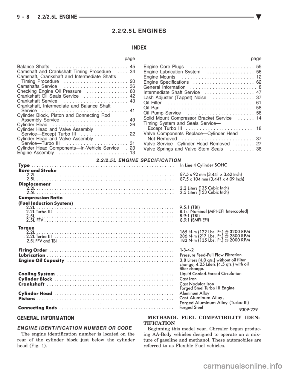
2.2/2.5L ENGINES INDEX
page page
Balance Shafts .......................... 45
Camshaft and Crankshaft Timing Procedure .... 34
Camshaft, Crankshaft and Intermediate Shafts Timing Procedure ....................... 20
Camshafts Service ....................... 36
Checking Engine Oil Pressure ............... 60
Crankshaft Oil Seals Service ................ 42
Crankshaft Service ....................... 43
Crankshaft, Intermediate and Balance Shaft Service ............................... 41
Cylinder Block, Piston and Connecting Rod Assembly Service ....................... 49
Cylinder Head ........................... 26
Cylinder Head and Valve Assembly ServiceÐExcept Turbo III ................. 22
Cylinder Head and Valve Assembly ServiceÐTurbo III ...................... 31
Cylinder Head ComponentsÐIn-Vehicle Service . 23
Engine Assembly ......................... 13 Engine Core Plugs
....................... 55
Engine Lubrication System ................. 56
Engine Mounts .......................... 12
Engine Specifications ...................... 62
General Information ........................ 8
Intermediate Shaft Service .................. 47
Lash Adjuster (Tappet) Noise ............... 37
Oil Filter ............................... 61
Oil Pan ................................ 58
Oil Pump Service ........................ 58
Solid Mount Compressor Bracket Service ...... 14
Timing System and Seals ServiceÐ Except Turbo III ........................ 18
Valve Components ReplaceÐCylinder Head Not Removed .......................... 37
Valve ServiceÐCylinder Head Removed ....... 27
Valve Springs and Valve Stem Seals ......... 38
GENERAL INFORMATION
ENGINE IDENTIFICATION NUMBER OR CODE
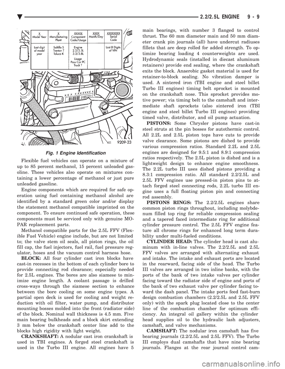
The engine identification number is located on the
rear of the cylinder block just below the cylinder
head (Fig. 1). METHANOL FUEL COMPATIBILITY IDEN-
TIFICATION Beginning this model year, Chrysler began produc-
ing AA-Body vehicles designed to operate on a mix-
ture of gasoline and methanol. These automobiles are
referred to as Flexible Fuel vehicles.
2.2/2.5L ENGINE SPECIFICATION
9 - 8 2.2/2.5L ENGINE Ä
Page 1575 of 2438
Flexible fuel vehicles can operate on a mixture of
up to 85 percent methanol, 15 percent unleaded gas-
oline. These vehicles also operate on mixtures con-
taining a lower percentage of methanol or just pure
unleaded gasoline. Engine components which are required for safe op-
eration using fuel containing methanol alcohol are
identified by a standard green color and/or display
the statement methanol compatible imprinted on the
component. To ensure continued safe operation, these
components must be serviced only with genuine MO-
PAR replacement parts. Methanol compatible parts for the 2.5L FFV (Flex-
ible Fuel Vehicle) engine include, but are not limited
to; the valve stem oil seals, all piston rings, the oil
fill cap, the fuel injectors, fuel rail, fuel pressure reg-
ulator, hoses and the vacuum control harness hose. BLOCK: All four cylinder cast iron blocks have
cast-in recesses in the bottom of each cylinder bore to
provide connecting rod clearance; especially needed
for 2.5L engines. The bores are also siamese to min-
imize engine length. A coolant passage is drilled
cross-ways through the siamese section to enhance
between the bore cooling on some engine types. A
partial open deck is used for cooling and weight re-
duction with oil filter, water pump, and distributor
mounting bosses molded into the front (radiator side)
of the block. Nominal wall thickness is 4.5 mm. Five
main bearing bulkheads and a block skirt extending
3 mm below the crankshaft center line add to the
blocks high rigidity with light weight. CRANKSHAFT: A nodular cast iron crankshaft is
used in TBI engines. A forged steel crankshaft is
used in the Turbo III engine. All engines have 5 main bearings, with number 3 flanged to control
thrust. The 60 mm diameter main and 50 mm diam-
eter crank pin journals (all) have undercut radiuses
fillets that are deep rolled for added strength. To op-
timize bearing loading 4 counterweights are used.
Hydrodynamic seals (installed in diecast aluminum
retainers) provide end sealing, where the crankshaft
exits the block. Anaerobic gasket material is used for
retainer-to-block sealing. No vibration damper is
used. A sintered iron (TBI engine and steel billet
Turbo III engines) timing belt sprocket is mounted
on the crankshaft nose. This sprocket provides mo-
tive power; via timing belt to the camshaft and inter-
mediate shaft sprockets (also sintered iron (TBI
engine and steel billet Turbo III engines) providing
timed valve, distributor, and oil pump actuation. PISTONS: Some Chrysler pistons have cast-in
steel struts at the pin bosses for autothermic control.
All 2.2L and 2.5L piston tops have cuts to provide
valve clearance. Some pistons are dished to provide
various compression ratios. Standard 2.2L and 2.5L
engines are designed for 9.5:1 and 8.9:1 compression
ratios respectively. The 2.5L piston is dished and is a
lightweight design to enhance engine smoothness.
The 2.2L turbo III uses dished pistons providing a
8.3:1 compression ratio. All standard 2.2/2.5L and
2.5L FFV engines use pressed-in piston pins to at-
tach forged steel connecting rods, 2.2L turbo III en-
gine uses a full floating piston pin and connecting
rod assembly. PISTONS RINGS: The 2.2/2.5L engines share
common piston rings throughout, including molybde-
num filled top ring for reliable compression sealing
and a tapered faced intermediate ring for additional
cylinder pressure control. The 2.5L FFV engine fea-
ture all chrome rings for enhanced long term dura-
bility under multi-fueled conditions. CYLINDER HEAD: The cylinder head is cast alu-
minum with in-line valves. The 2.2/2.5L and 2.5L
FFV valves are arranged with alternating exhaust
and intake. The intake and exhaust ports are located
in the rearward, facing side of the head. The Turbo
III valves are arranged in two inline banks, with the
ports of the bank of two intake valves per cylinder
facing toward the radiator side of engine and ports of
the bank of two exhaust valve per cylinder facing to-
ward the dash panel. The intake ports feed fast-burn
design combustion chambers (2.2/2.5L and 2.5L FFV
only) with the spark plug located close to the center
line of the combustion chamber for optimum effi-
ciency. An integral oil gallery within the cylinder
head supplies oil to the hydraulic lash adjusters,
camshaft, and valve mechanisms. CAMSHAFT: The nodular iron camshaft has five
bearing journals (2.2/2.5L and 2.5L FFV). The Turbo
III employs dual camshafts that have nine bearing
journals. Flanges at the rear journal control cam-
Fig. 1 Engine Identification
Ä 2.2/2.5L ENGINE 9 - 9
Page 1576 of 2438
shaft end play. A sintered iron (TBI engine and steel
billet Turbo III engines) timing belt sprocket is
mounted on the cam nose, and a hydrodynamic oil
seal is used for oil control at the front of the cam-
shaft. ACCESSORY SHAFT: The iron accessory shaft
has two bearing journals and is housed in the for-
ward facing side of the block. A hydrodynamic seal,
installed in an aluminum housing attached to the
block, provides retention, shaft thrust, and oil con-
trol. The accessory shaft is driven by the timing belt
through a sintered iron (TBI engine and steel billet
Turbo III engines) sprocket mounted on the nose of
the accessory shaft. The accessory shaft in turn
drives the oil pump and distributor on 2.2/2.5L and
2.5L FFV and the oil pump only on Turbo III. VALVES: The valves are actuated by roller cam
followers which pivot on stationary hydraulic lash
adjusters. The valve train with 40.6 mm (1.60 inch)
diameter intake valves and 35.4 mm (1.39 inch) di-
ameter exhaust valves employ viton rubber valve
stem seals except 2.5L FFv . the 2.5L FFV valve
stem seals are made of special rubber compound
which resist the deteriorating effects of methanol
fuel by-products that enter the oil during combus-
tion. Valve springs, spring retainers, and locks are
conventional. For Turbo III engines the valves are
actuated by roller tipped rocker arms with hydraulic
lash adjusters which pivot on a shaft. The valve train
with 33.88 mm (1.33 in.) diameter intake valves are
arranged in line opposite of the 29.26 mm (1.15 in.)
diameter exhaust valves employ locking valve stem
seals. Valve springs, spring retainers, and locks are
not interchangeable with other engines. BALANCE SHAFTS: 2.2 Turbo III and 2.5L en-
gines are equipped with two counter rotating balance
shafts installed in a carrier attached to the lower
crankcase. The shafts are interconnect through
gears. These gears are driven by a short chain from
the crankshaft, to rotate at two times crankshaft
speed. This counterbalances certain engine recipro-
cating forces. INTAKE MANIFOLDS:
All intake manifolds are
aluminum castings, attached to the cylinder head
with eight bolts. N.A. engines use a four branch de-
sign. This long branch fan design enhances low and
midspeed torque. It also features an integrally cast
water crossover passage to warm incoming fuel/air
mixture, plus an EGR mounting boss and PCV inlet. The Turbo III engine intake manifold is a log type
with tuned runners. The manifold is machined to ac-
cept fuel injectors near the ports of each cylinder. EXHAUST MANIFOLDS: The exhaust manifolds
are made of nodular cast iron for strength and high
temperatures. All naturally aspirated (N.A.) and tur-
bocharged engines exit exhaust gasses through a ma-
chined, articulated joint connection to the exhaust
pipe. 2.2/2.5L and 2.5L FFV manifolds intermesh
with the intake manifold at the cylinder head. N.A. engines use a four branch design with cylin-
ders one and four joined and cylinder two and three
joined to exit at the outlet. The Turbo III engine exhaust manifold also carries
the turbocharger. This manifold has a modified log
type collector with exhaust gasses directed to and
through the turbocharger to exit the conical (articu-
lated joint) outlet machined into the turbocharger ex-
haust elbow. ENGINE LUBRICATION: Refer to Group 0 Lu-
brication and Maintenance for recommended oil to be
used in various engine application. System is full
flow filtration, pressure feed type. The oil pump is
mounted within the crankcase and driven by the ac-
cessory shaft. Pressurized oil is then routed through
the main oil gallery, running the length of the cylin-
der block, supplying main and rod bearings with fur-
ther routing (for 2.2L turbo III and 2.5L engines) to
the lower balance shaft assemblies. Pistons are lubri-
cated from directed holes in the connecting rod as-
semblies. Camshaft and valve mechanisms are
lubricated from a full-length cylinder head oil gallery
supplied from the crankcase main oil gallery.
9 - 10 2.2/2.5L ENGINE Ä
Page 1592 of 2438
valve spring retainer locks to become dislocated
when depressing the valve spring. Check and make
sure the locks are in their proper location. (3) Install valve cover as previously outlined in
this section.
VALVE SPRINGS AND VALVE STEM SEALS
REMOVAL
(1) Remove rocker arms as previously outlined in
this section. (2) Rotate crankshaft until piston is at TDC on
compression. (3) With air hose attached to adapter tool installed
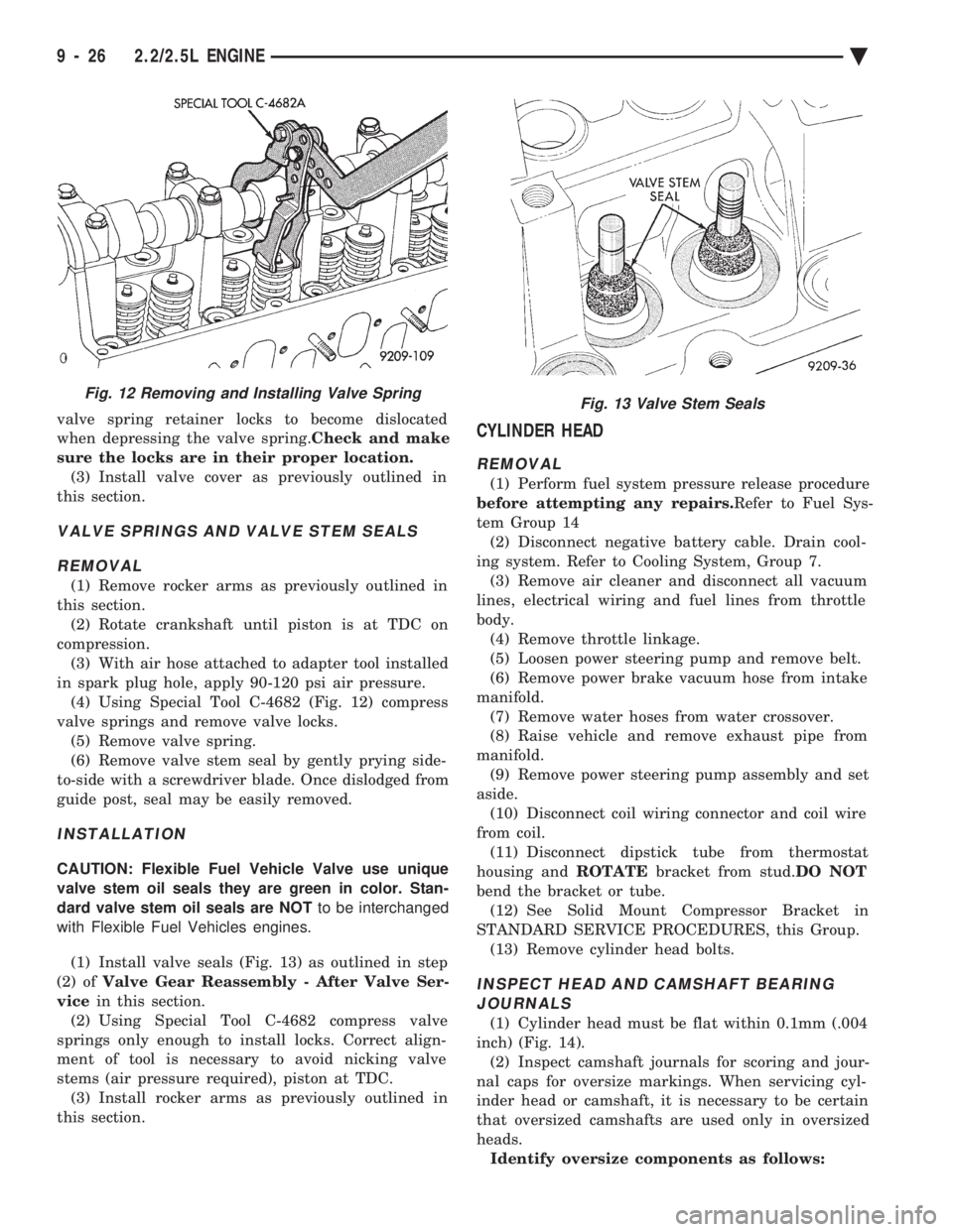
in spark plug hole, apply 90-120 psi air pressure. (4) Using Special Tool C-4682 (Fig. 12) compress
valve springs and remove valve locks. (5) Remove valve spring.
(6) Remove valve stem seal by gently prying side-
to-side with a screwdriver blade. Once dislodged from
guide post, seal may be easily removed.
INSTALLATION
CAUTION: Flexible Fuel Vehicle Valve use unique
valve stem oil seals they are green in color. Stan-
dard valve stem oil seals are NOT to be interchanged
with Flexible Fuel Vehicles engines.
(1) Install valve seals (Fig. 13) as outlined in step
(2) of Valve Gear Reassembly - After Valve Ser-
vice in this section.
(2) Using Special Tool C-4682 compress valve
springs only enough to install locks. Correct align-
ment of tool is necessary to avoid nicking valve
stems (air pressure required), piston at TDC. (3) Install rocker arms as previously outlined in
this section.
CYLINDER HEAD
REMOVAL
(1) Perform fuel system pressure release procedure
before attempting any repairs. Refer to Fuel Sys-
tem Group 14 (2) Disconnect negative battery cable. Drain cool-
ing system. Refer to Cooling System, Group 7. (3) Remove air cleaner and disconnect all vacuum
lines, electrical wiring and fuel lines from throttle
body. (4) Remove throttle linkage.
(5) Loosen power steering pump and remove belt.
(6) Remove power brake vacuum hose from intake
manifold. (7) Remove water hoses from water crossover.
(8) Raise vehicle and remove exhaust pipe from
manifold. (9) Remove power steering pump assembly and set
aside. (10) Disconnect coil wiring connector and coil wire
from coil. (11) Disconnect dipstick tube from thermostat
housing and ROTATEbracket from stud. DO NOT
bend the bracket or tube. (12) See Solid Mount Compressor Bracket in
STANDARD SERVICE PROCEDURES, this Group. (13) Remove cylinder head bolts.
INSPECT HEAD AND CAMSHAFT BEARINGJOURNALS
(1) Cylinder head must be flat within 0.1mm (.004
inch) (Fig. 14). (2) Inspect camshaft journals for scoring and jour-
nal caps for oversize markings. When servicing cyl-
inder head or camshaft, it is necessary to be certain
that oversized camshafts are used only in oversized
heads. Identify oversize components as follows:
Fig. 12 Removing and Installing Valve SpringFig. 13 Valve Stem Seals
9 - 26 2.2/2.5L ENGINE Ä
Page 1613 of 2438
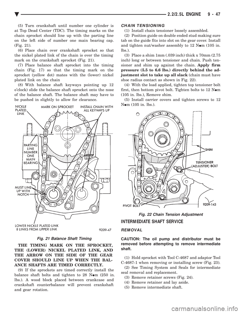
(5) Turn crankshaft until number one cylinder is
at Top Dead Center (TDC). The timing marks on the
chain sprocket should line up with the parting line
on the left side of number one main bearing cap.
(Fig. 21). (6) Place chain over crankshaft sprocket so that
the nickel plated link of the chain is over the timing
mark on the crankshaft sprocket (Fig. 21). (7) Place balance shaft sprocket into the timing
chain (Fig. 17) so that the timing mark on the
sprocket (yellow dot) mates with the (lower) nickel
plated link on the chain (8) With balance shaft keyways pointing up 12
o'clock) slide the balance shaft sprocket onto the nose
of the balance shaft. The balance shaft may have to
be pushed in slightly to allow for clearance.
THE TIMING MARK ON THE SPROCKET,
THE (LOWER) NICKEL PLATED LINK, AND
THE ARROW ON THE SIDE OF THE GEAR
COVER SHOULD LINE UP WHEN THE BAL-
ANCE SHAFTS ARE TIMED CORRECTLY. (9) If the sprockets are timed correctly install the
balance shaft bolts and tighten to 28 N Im (250 in.
lbs.). A wood block placed between crankcase and
crankshaft counterbalance will prevent crankshaft
and gear rotation.CHAIN TENSIONING
(1) Install chain tensioner loosely assembled.
(2) Position guide on double ended stud making sure
tab on the guide fits into slot on the gear cover. Install
and tighten nut/washer assembly to 12 N Im (105 in.
lbs.). (3) Place a shim 1mm (.039 inch) thick x 70mm (2.75
inch) long or between tensioner and chain. Push ten-
sioner and shim up against the chain. Apply firm
pressure (5.5 to 6.6 lbs.) directly behind the ad-
justment slot to take up all slack (chain must have
shoe radius contact as shown in Fig. 22). (4) With the load applied, tighten top tensioner bolt
first, then bottom pivot bolt. Tighten bolts to 12 N Im
(105 in. lbs.), Remove shim. (5) Install carrier covers and tighten screws to 12
N Im (105 in. lbs.).
INTERMEDIATE SHAFT SERVICE
REMOVAL
CAUTION: The oil pump and distributor must be
removed before attempting to remove intermediate
shaft.
(1) Hold sprocket with Tool C-4687 and adaptor Tool
C-4687-1 when removing or installing screw (Fig. 23). (2) See Timing System and Seals for intermediate
seal removal and replacement. (3) Remove retainer screws (Fig. 24).
(4) Remove retainer and lay aside.
(5) Remove intermediate shaft.Fig. 21 Balance Shaft Timing
Fig. 22 Chain Tension Adjustment
Ä 2.2/2.5L ENGINE 9 - 47
Page 1624 of 2438
OIL PAN
A formed steel oil pan provides lower engine pro-
tection as well as serving as the engine oil reservoir
(Fig. 1). Pan side flanges to block are sealed with
gaskets. The oil pickup tube for some 2.2L engines
have a circular strainer and cover. The 2.5L engine
pickup is also unsupported and the lower end has a
box type strainer (Fig. 4).
PRESSURE LUBRICATION
Oil drawn up through the pickup tube is pressur-
ized by the pump and routed through the full flow
filter to the main oil gallery running the length of
the cylinder block (Fig. 2). Modified oil pickup, pump
and check valve provide increased oil flow to the
main oil gallery.
MAIN/ROD BEARINGS
A diagonal hole in each bulkhead feeds oil to each
main bearing. Drilled passages within the crankshaft
route oil from main bearing journals to crankpin
journals.
ACCESSORY SHAFT
Two separate holes supply the accessory shaft for
the N/A engines. For Turbo III engines there is a slot
in the rear shaft bushing that squirts oil onto the
oil pump drive gears (Fig. 2).
BALANCE SHAFTS
The engine balance shafts are lubricated by an ad-
ditional hole that interconnects a passage in one leg
of the balance shaft carrier to route oil down to the
carrier oil gallery. This gallery directly supplies the
balance shafts front bearings and internal machined
passages in the shafts routes oil from front to rear
shaft bearing journals.
TURBOCHARGER (WHERE EQUIPPED)
If turbocharger equipped, pressurized oil from the
main gallery to sending unit hex fitting is piped from
the fitting to the turbocharger bearing housing.
From the housing a hose and tube connection to a
machined hole in the block provides drainback.
CAMSHAFT/HYDRAULIC LIFTERS
A vertical hole at the number five bulkhead routes
pressurized oil through a restrictor up past a cylinder
head bolt to an oil gallery running the length of the
cylinder head. For 2.2/2.5L and 2.5L FFV engines
hydraulic adjusters are supplied directly from this
gallery while diagonal holes supply oil to the cam-
shaft journals. The camshaft journals are partially
slotted to allow a predetermined amount of pressur-
ized oil to pass into the bearing cap cavities with
small holes directed to spray lubricate the camshaft
lobes. For Turbo III engines oil is supplied thru oil
galleries in the head to the camshafts and rocker arm shafts which feed oil to the lash adjusters. Oil is
feed thru the rocker arms to lubricate the rollers and
the camshaft lobes.
SPLASH LUBRICATION
Oil returning to the pan from pressurized compo-
nents supplies lubrication to the valve stems. Cylinder
bores and wrist pins are splash lubricated from di-
rected holes in the connecting rods.
OIL PAN
REMOVAL
(1) Drain engine oil and remove oil pan.
(2) Clean oil pan and all gasket surfaces.
OIL PAN RAIL TO BLOCK SEALING
For all engines side gaskets (Fig. 1) are employed for
rail sealing.
INSTALLATION
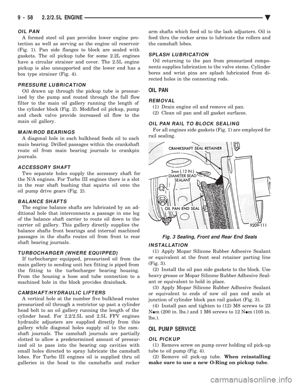
(1) Apply Mopar Silicone Rubber Adhesive Sealant
or equivalent at the front seal retainer parting line
(Fig. 3). (2) Install the oil pan side gaskets to the block. Use
heavy grease or Mopar Silicone Rubber Adhesive Seal-
ant or equivalent to hold in place. (3) Apply Mopar Silicone Rubber Adhesive Sealant
or equivalent to ends of new oil pan end seals at
junction of cylinder block pan rail gasket (Fig. 3). (4) Install pan and tighten to (12) M8 screws to 23
N Im (200 in. lbs.) and 1 M6 screws to 12 N Im (105 in.
lbs.).
OIL PUMP SERVICE
OIL PICKUP
(1) Remove screw on pump cover holding oil pick-up
tube to oil pump (Fig. 4). (2) Remove oil pick-up tube. When reinstalling
make sure to use a new O-Ring on pickup tube .
Fig. 3 Sealing, Front and Rear End Seals
9 - 58 2.2/2.5L ENGINE Ä
Page 1632 of 2438
3.0L ENGINE INDEX
page page
Accessory Drive Belt Service ................ 70
Auto Lash Adjuster ....................... 75
Camshaft Service ........................ 76
Checking Engine Oil Pressure ............... 93
Crankshaft and Cylinder Block, Assembly Service . 86
Cylinder Block ........................... 89
Cylinder Head ........................... 78
Cylinder Head and Camshaft Service ......... 75
Engine Assembly ......................... 69
Engine Lubrication System ................. 91
Engine Mounts .......................... 68 Engine Specifications
..................... 95
General Information ....................... 66
Oil Filter and Bracket ..................... 94
Oil Pan ................................ 92
Oil Pump Service ........................ 92
Piston and Connecting Rod Assembly Service . . . 82
Timing Belt InspectionÐIn Vehicle ............ 72
Timing Belt Service ....................... 72
Valve Service ........................... 80
GENERAL INFORMATION
ENGINE IDENTIFICATION NUMBER OR CODE
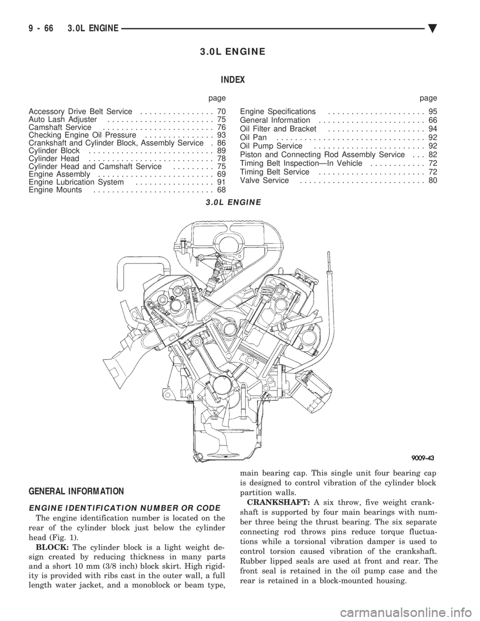
The engine identification number is located on the
rear of the cylinder block just below the cylinder
head (Fig. 1). BLOCK: The cylinder block is a light weight de-
sign created by reducing thickness in many parts
and a short 10 mm (3/8 inch) block skirt. High rigid-
ity is provided with ribs cast in the outer wall, a full
length water jacket, and a monoblock or beam type, main bearing cap. This single unit four bearing cap
is designed to control vibration of the cylinder block
partition walls.
CRANKSHAFT: A six throw, five weight crank-
shaft is supported by four main bearings with num-
ber three being the thrust bearing. The six separate
connecting rod throws pins reduce torque fluctua-
tions while a torsional vibration damper is used to
control torsion caused vibration of the crankshaft.
Rubber lipped seals are used at front and rear. The
front seal is retained in the oil pump case and the
rear is retained in a block-mounted housing.
3.0L ENGINE
9 - 66 3.0L ENGINE Ä