1993 CHEVROLET PLYMOUTH ACCLAIM length
[x] Cancel search: lengthPage 1666 of 2438
(3) Remove the thru bolt from the insulator assem-
bly. Remove insulator. (4) Reverse removal procedure for installation. Re-
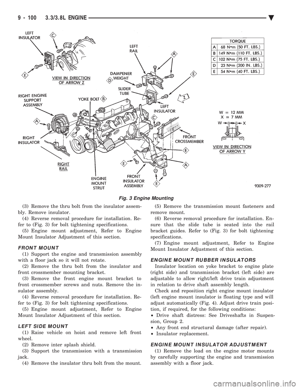
fer to (Fig. 3) for bolt tightening specifications. (5) Engine mount adjustment, Refer to Engine
Mount Insulator Adjustment of this section.
FRONT MOUNT
(1) Support the engine and transmission assembly
with a floor jack so it will not rotate. (2) Remove the thru bolt from the insulator and
front crossmember mounting bracket. (3) Remove the front engine mount bracket to
front crossmember screws and nuts. Remove the in-
sulator assembly. (4) Reverse removal procedure for installation. Re-
fer to (Fig. 3) for bolt tightening specifications. (5) Engine mount adjustment, Refer to Engine
Mount Insulator Adjustment of this section.
LEFT SIDE MOUNT
(1) Raise vehicle on hoist and remove left front
wheel. (2) Remove inter splash shield.
(3) Support the transmission with a transmission
jack. (4) Remove the insulator thru bolt from the mount. (5) Remove the transmission mount fasteners and
remove mount. (6) Reverse removal procedure for installation. En-
sure that the slide tube is seated into the rail
bracket guides. Refer to (Fig. 3) for bolt tightening
specifications. (7) Engine mount adjustment, Refer to Engine
Mount Insulator Adjustment of this section.
ENGINE MOUNT RUBBER INSULATORS
Insulator location on yoke bracket to engine plate
(right side) and transmission bracket (left side) are
adjustable to allow right/left drive train adjustment
in relation to drive shaft assembly length. Check and reposition right engine mount insulator
(left engine mount insulator is floating type and will
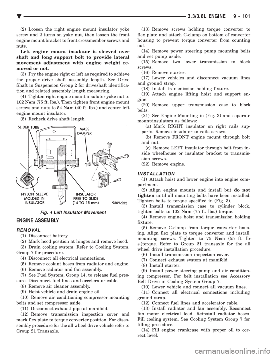
adjust automatically (Fig. 4). Adjust drive train posi-
tion, if required, for the following conditions:
² Drive shaft distress: See Driveshafts in Suspen-
sion, Group 2.
² Any front end structural damage (after repair).
² Insulator replacement.
ENGINE MOUNT INSULATOR ADJUSTMENT
(1) Remove the load on the engine motor mounts
by carefully supporting the engine and transmission
assembly with a floor jack.
Fig. 3 Engine Mounting
9 - 100 3.3/3.8L ENGINE Ä
Page 1667 of 2438
(2) Loosen the right engine mount insulator yoke
screw and 2 turns on yoke nut, then loosen the front
engine mount bracket to front crossmember screws and
nuts. Left engine mount insulator is sleeved over
shaft and long support bolt to provide lateral
movement adjustment with engine weight re-
moved or not. (3) Pry the engine right or left as required to achieve
the proper drive shaft assembly length. See Drive
Shaft in Suspension Group 2 for driveshaft identifica-
tion and related assembly length measuring. (4) Tighten right engine mount insulator yoke nut to
102 N Im (75 ft. lbs.). Then tighten front engine mount
screws and nuts to 54 N Im (40 ft. lbs.) and center left
engine mount insulator. (5) Recheck drive shaft length.
ENGINE ASSEMBLY
REMOVAL
(1) Disconnect battery.
(2) Mark hood position at hinges and remove hood.
(3) Drain cooling system. Refer to Cooling System,
Group 7 for procedure. (4) Disconnect all electrical connections.
(5) Remove coolant hoses from radiator and engine.
(6) Remove radiator and fan assembly.
(7) See Fuel System, Group 14, to release fuel pres-
sure. Disconnect fuel lines and accelerator cable. (8) Remove air cleaner assembly.
(9) Hoist vehicle and drain engine oil.
(10) Remove air conditioning compressor mounting
bolts and set compressor aside. (11) Disconnect exhaust pipe at manifold.
(12) Remove transmission inspection cover and
mark flex plate to torque converter position. For disas-
sembly procedure for the all wheel drive vehicle refer to
Group 21 Transaxle. (13) Remove screws holding torque converter to
flex plate and attach C-clamp on bottom of converter
housing to prevent torque converter from counting
out. (14) Remove power steering pump mounting bolts
and set pump aside. (15) Remove two lower transmission to block
screws. (16) Remove starter.
(17) Lower vehicles and disconnect vacuum lines
and ground strap. (18) Install transmission holding fixture.
(19) Attach engine lifting hoist and support en-
gine. (20) Remove upper transmission case to block
bolts. (21) See Engine Mounting in (Fig. 3) and separate
mount/insulators as follows: (a) Mark RIGHT insulator on right rails sup-
ports. Remove insulator to rails screws. (b) Remove FRONT engine mount through bolt
and nut. (c) Remove LEFT insulator through bolt from in-
side wheelhouse or insulator bracket to transmis-
sion screws.
(22) Remove engine.
INSTALLATION
(1) Attach hoist and lower engine into engine com-
partment. (2) Align engine mounts and install but do not
tighten until all mounting bolts have been installed.
Tighten bolts to torque specified in (Fig. 3). (3) Install transmission case to cylinder block,
tighten bolts to 102 N Im (75 ft. lbs.) torque.
(4) Remove engine hoist and transmission holding
fixture. (5) Remove C-clamp from torque converter hous-
ing. Align flex plate to torque converter and install
mounting screws. Tighten to 75 N Im (55 ft. lb-
s.)torque. Refer to Group 21 transaxle for the all
wheel drive installation procedure. (6) Install transmission inspection cover.
(7) Connect exhaust system at manifold.
(8) Install starter.
(9) Install power steering pump and air condition-
ing compressor. For belt installation see Accessory
Belt Drive in Cooling System Group 7. (10) Lower vehicle and connect all vacuum lines.
(11) Connect all electrical connections including
ground strap. (12) Connect fuel lines and accelerator cable.
(13) Install radiator and fan assembly. Reconnect
fan motor electrical lead. Reinstall radiator hoses.
Fill cooling system. See Cooling System Group 7 for
filling procedure. (14) Fill engine crankcase with proper oil to cor-
rect level.
Fig. 4 Left Insulator Movement
Ä 3.3/3.8L ENGINE 9 - 101
Page 1669 of 2438
INSPECTION
(1) Before cleaning, check for leaks, damage and
cracks. (2) Clean cylinder head and oil passages.
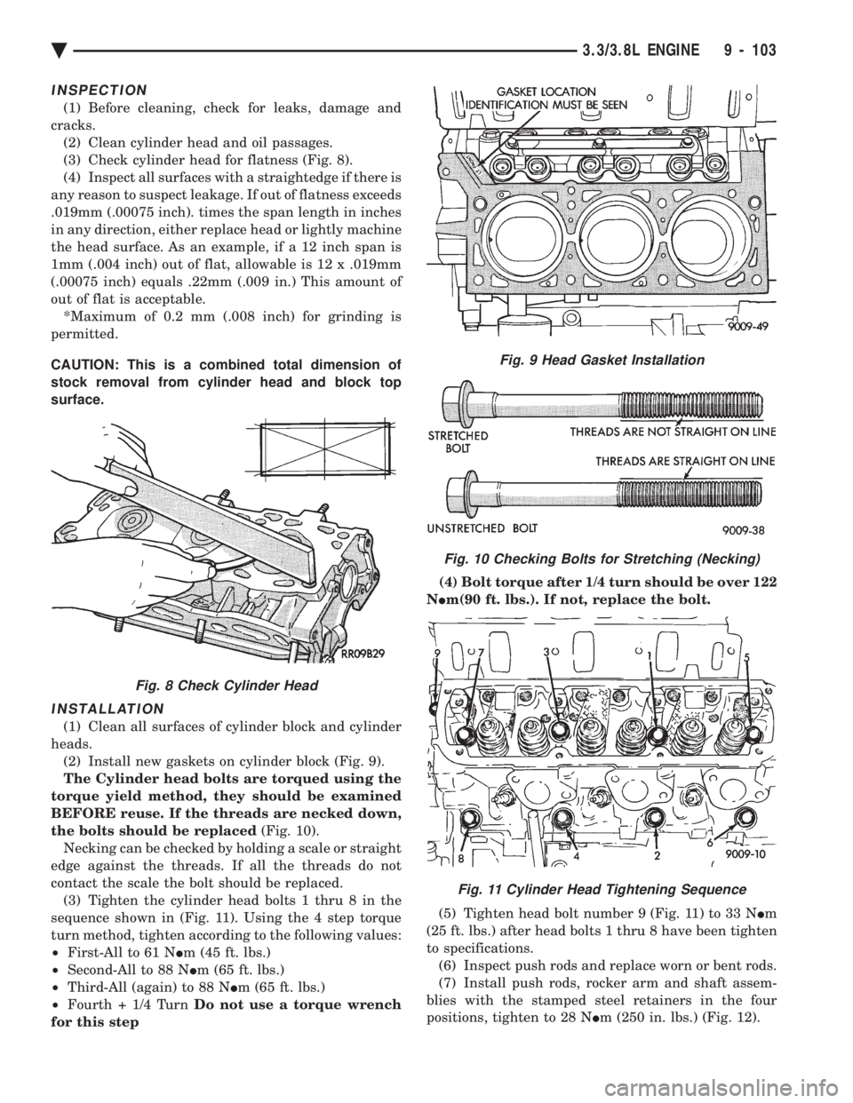
(3) Check cylinder head for flatness (Fig. 8).
(4) Inspect all surfaces with a straightedge if there is
any reason to suspect leakage. If out of flatness exceeds
.019mm (.00075 inch). times the span length in inches
in any direction, either replace head or lightly machine
the head surface. As an example, if a 12 inch span is
1mm (.004 inch) out of flat, allowable is 12 x .019mm
(.00075 inch) equals .22mm (.009 in.) This amount of
out of flat is acceptable. *Maximum of 0.2 mm (.008 inch) for grinding is
permitted.
CAUTION: This is a combined total dimension of
stock removal from cylinder head and block top
surface.
INSTALLATION
(1) Clean all surfaces of cylinder block and cylinder
heads. (2) Install new gaskets on cylinder block (Fig. 9).
The Cylinder head bolts are torqued using the
torque yield method, they should be examined
BEFORE reuse. If the threads are necked down,
the bolts should be replaced (Fig. 10).
Necking can be checked by holding a scale or straight
edge against the threads. If all the threads do not
contact the scale the bolt should be replaced. (3) Tighten the cylinder head bolts 1 thru 8 in the
sequence shown in (Fig. 11). Using the 4 step torque
turn method, tighten according to the following values:
² First-All to 61 N Im (45 ft. lbs.)
² Second-All to 88 N Im (65 ft. lbs.)
² Third-All (again) to 88 N Im (65 ft. lbs.)
² Fourth + 1/4 Turn Do not use a torque wrench
for this step (4) Bolt torque after 1/4 turn should be over 122
N Im(90 ft. lbs.). If not, replace the bolt.
(5) Tighten head bolt number 9 (Fig. 11) to 33 N Im
(25 ft. lbs.) after head bolts 1 thru 8 have been tighten
to specifications. (6) Inspect push rods and replace worn or bent rods.
(7) Install push rods, rocker arm and shaft assem-
blies with the stamped steel retainers in the four
positions, tighten to 28 N Im (250 in. lbs.) (Fig. 12).
Fig. 8 Check Cylinder Head
Fig. 9 Head Gasket Installation
Fig. 10 Checking Bolts for Stretching (Necking)
Fig. 11 Cylinder Head Tightening Sequence
Ä 3.3/3.8L ENGINE 9 - 103
Page 1673 of 2438
length of the spring to be tested is 33.34mm (1-5/16
inches). Turn table of Tool C-647 until surface is in line
with the 33.34mm (1-5/16 inch) mark on the threaded
stud and the zero mark on the front. Place spring over
stud on the table and lift compressing lever to set tone
device. Pull on torque wrench until ping is heard. Take
reading on torque wrench at this instant. Multiply this
reading by two. This will give the spring load at test
length. Fractional measurements are indicated on the
table for finer adjustments. Refer to specifications to
obtain specified height and allowable tensions. Discard
the springs that do not meet specifications.
VALVE INSTALLATION
(1) Coat valve stems with clean engine oil and insert
them in cylinder head. (2) Check valve tip to spring seat dimension A after
grinding the valve seats or faces. Grind valve tip to give
49.541 to 51.271 mm (1.950 to 2.018 inch.) over spring
seat when installed in the head (Fig. 17). Check valve
tip for scoring, if necessary, the tip chamfer should be
reground to prevent seal damage when the valve is
installed. (3) Install new cup seals on all valve stems and over
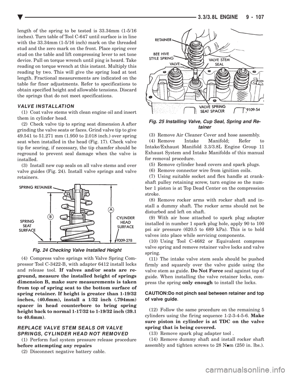
valve guides (Fig. 24). Install valve springs and valve
retainers.
(4) Compress valve springs with Valve Spring Com-
pressor Tool C-3422-B, with adapter 6412 install locks
and release tool. If valves and/or seats are re-
ground, measure the installed height of springs
dimension B, make sure measurements is taken
from top of spring seat to the bottom surface of
spring retainer. If height is greater than 1-19/32
inches, (40.6mm), install a 1/32 inch (.794mm)
spacer in head counterbore to bring spring
height back to normal 1-17/32 to 1-19/32 inch (39.1
to 40.6mm) .
REPLACE VALVE STEM SEALS OR VALVE
SPRINGS, CYLINDER HEAD NOT REMOVED
(1) Perform fuel system pressure release procedure
before attempting any repairs (2) Disconnect negative battery cable. (3) Remove Air Cleaner Cover and hose assembly.
(4) Remove Intake Manifold; Refer to
Intake/Exhaust Manifold 3.3/3.8L Engine Group 11
Exhaust System and Intake Manifolds of this manual
for removal procedure. (5) Remove cylinder head covers and spark plugs.
(6) Remove connector wire from ignition coils.
(7) Using suitable socket and flex handle at crank-
shaft pulley retaining screw, turn engine so the num-
ber 1 piston is at Top Dead Center on the compression
stroke. (8) Remove rocker arms with rocker shaft and in-
stall a dummy shaft. The rocker arms should not be
disturbed and left on shaft. (9) With air hose attached to spark plug adapter
installed in number 1 spark plug hole, apply 90 to 100
psi air pressure (620.5 to 689 kPa). This is to hold
valves into place while servicing components. (10) Using Tool C-4682 or Equivalent compress
valve spring and remove retainer valve locks and valve
spring. (11) The intake valve stem seals should be pushed
firmly and squarely over the valve guide using the
valve stem as guide. Do Not Forceseal against top of
guide. When installing the valve retainer locks, com-
press the spring only enoughto install the locks.
CAUTION:Do not pinch seal between retainer and top
of valve guide .
(12) Follow the same procedure on the remaining 5
cylinders using the firing sequence 1-2-3-4-5-6. Make
sure piston in cylinder is at TDC on the valve
spring that is being covered. (13) Remove spark plug adapter tool .
(14) Remove dummy shaft and install rocker shaft
assembly and tighten screws to 28 N Im (250 in. lbs.).
Fig. 24 Checking Valve Installed Height
Fig. 25 Installing Valve, Cup Seal, Spring and Re-
tainer
Ä 3.3/3.8L ENGINE 9 - 107
Page 1686 of 2438
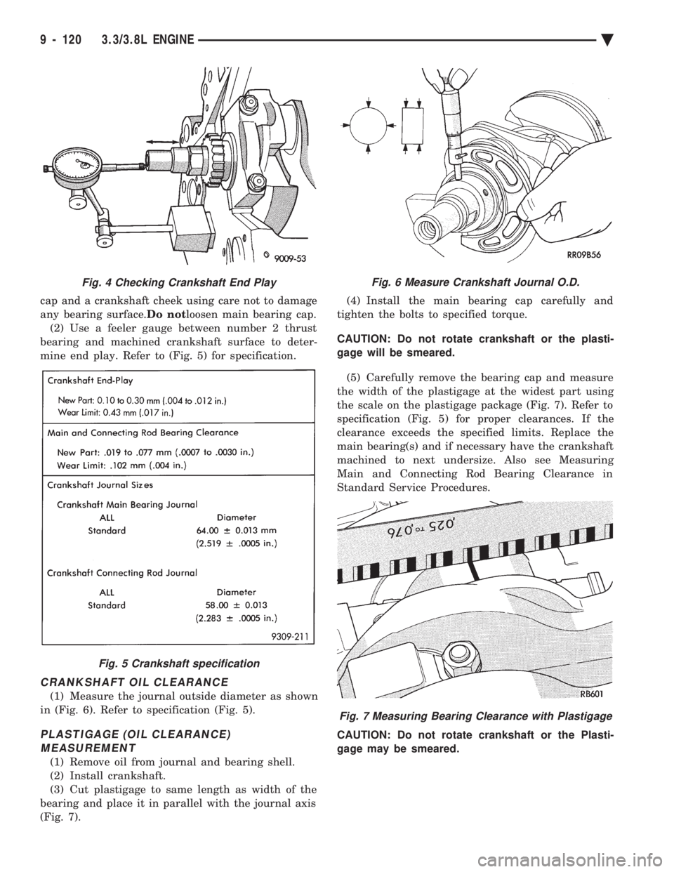
cap and a crankshaft cheek using care not to damage
any bearing surface. Do notloosen main bearing cap.
(2) Use a feeler gauge between number 2 thrust
bearing and machined crankshaft surface to deter-
mine end play. Refer to (Fig. 5) for specification.
CRANKSHAFT OIL CLEARANCE
(1) Measure the journal outside diameter as shown
in (Fig. 6). Refer to specification (Fig. 5).
PLASTIGAGE (OIL CLEARANCE) MEASUREMENT
(1) Remove oil from journal and bearing shell.
(2) Install crankshaft.
(3) Cut plastigage to same length as width of the
bearing and place it in parallel with the journal axis
(Fig. 7). (4) Install the main bearing cap carefully and
tighten the bolts to specified torque.
CAUTION: Do not rotate crankshaft or the plasti-
gage will be smeared.
(5) Carefully remove the bearing cap and measure
the width of the plastigage at the widest part using
the scale on the plastigage package (Fig. 7). Refer to
specification (Fig. 5) for proper clearances. If the
clearance exceeds the specified limits. Replace the
main bearing(s) and if necessary have the crankshaft
machined to next undersize. Also see Measuring
Main and Connecting Rod Bearing Clearance in
Standard Service Procedures.
CAUTION: Do not rotate crankshaft or the Plasti-
gage may be smeared.
Fig. 4 Checking Crankshaft End Play
Fig. 5 Crankshaft specification
Fig. 6 Measure Crankshaft Journal O.D.
Fig. 7 Measuring Bearing Clearance with Plastigage
9 - 120 3.3/3.8L ENGINE Ä
Page 1690 of 2438
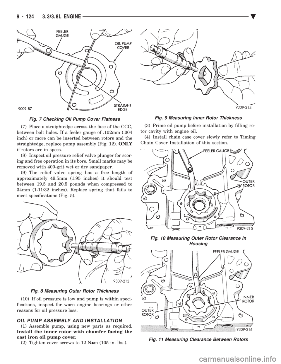
(7) Place a straightedge across the face of the CCC,
between bolt holes. If a feeler gauge of .102mm (.004
inch) or more can be inserted between rotors and the
straightedge, replace pump assembly (Fig. 12). ONLY
if rotors are in specs. (8) Inspect oil pressure relief valve plunger for scor-
ing and free operation in its bore. Small marks may be
removed with 400-grit wet or dry sandpaper. (9) The relief valve spring has a free length of
approximately 49.5mm (1.95 inches) it should test
between 19.5 and 20.5 pounds when compressed to
34mm (1-11/32 inches). Replace spring that fails to
meet specifications (Fig. 5).
(10) If oil pressure is low and pump is within speci-
fications, inspect for worn engine bearings or other
reasons for oil pressure loss.
OIL PUMP ASSEMBLY AND INSTALLATION
(1) Assemble pump, using new parts as required.
Install the inner rotor with chamfer facing the
cast iron oil pump cover. (2) Tighten cover screws to 12 N Im (105 in. lbs.). (3) Prime oil pump before installation by filling ro-
tor cavity with engine oil. (4) Install chain case cover slowly refer to Timing
Chain Cover Installation of this section.
Fig. 9 Measuring Inner Rotor Thickness
Fig. 10 Measuring Outer Rotor Clearance in Housing
Fig. 11 Measuring Clearance Between Rotors
Fig. 7 Checking Oil Pump Cover Flatness
Fig. 8 Measuring Outer Rotor Thickness
9 - 124 3.3/3.8L ENGINE Ä
Page 1703 of 2438
CLEANING AND INSPECTION
(1) Discard gaskets and clean all gasket surfaces
on both manifolds and on cylinder head. (2) Test gasket surfaces of manifolds for flatness
with a straight edge. Surfaces must be flat within
0.15mm per 300mm (.006 in. per foot) of manifold
length. (3) Inspect manifolds for cracks and distortion.
INSTALLATION
(1) Install a new intake and exhaust manifold gas-
ket. Coat steel gasket lightly with Gasket Sealer on
manifold side. Do notcoat composition gasket with
(any) sealer. (2) Set exhaust manifold in place. Tighten retain-
ing nuts starting at center and progressing outward
in both directions to 23 N Im (200 in. lbs.) torque. Re-
peat this procedure until all nuts are at specified
torque. (3) Set intake manifold in place.
(4) Raise vehicle and tighten retaining screws
starting at center and progressing outward in both
directions to 23 N Im (200 in. lbs.) torque (Fig. 3). Re-
peat this procedure until all screws are at specified
torque. (5) Reverse removal procedures 1-9 for installation.
(6) With the DRBII Scan Tool use ASD Fuel Sys-
tem Test to pressurize system to check for leaks.
CAUTION: When using the ASD Fuel System Test,
the Auto Shutdown (ASD) relay will remain ener-
gized for 7 minutes or until the ignition switch is
turned to the OFF position, or Stop All Test is se-
lected.
INTAKE AND EXHAUST MANIFOLDSÐFLEXIBLE
FUEL ENGINE
INTAKE MANIFOLD
The manifold is die-cast aluminum with upper ple-
num and 4 tubes lower runners. These attach to the
cylinder head, with each runner leading directly to a
cylinder. The manifold is also machined for fuel rail attach-
ment and injector installation. The throttle body is
installed on the upper plenum of the manifold.
EXHAUST MANIFOLD
All high strength iron casting that intermesh with
the intake manifold. For standard engines a four
branch design collects and directs exhaust gases to
the conical (articulated joint connection) outlet.
INTAKE/EXHAUST MANIFOLDS
SERVICEÐFLEXIBLE FUEL ENGINES
Intake and exhaust manifolds use a one piece gas-
ket. Service procedures requiring removal and instal-
lation of either must include both manifolds.
SERVICE PRECAUTIONS
Methanol is more toxic than gasoline. Always re-
lease fuel system pressure before servicing fuel sys-
tem components and wear methanol resistant gloves
and eye protection. Avoid breathing methanol vapors or ingesting
methanol. Headaches, dizziness and even uncon-
sciousness could result from breathing these vapors.
Serious injury, blindness and even death could result
from ingesting methanol. Methanol vapors are extremely flammable and can
travel along the ground. Service vehicles in well ven-
tilated areas and avoid ignition sources. Never
smoke while servicing the vehicle. Do not allow methanol to contact skin. Prolonged
contact with methanol can cause dry skin or an al-
lergic skin reaction. Also, prolonged contact could re-
sult in absorption through the skin.
FUEL SYSTEM PRESSURE RELEASE PROCEDURE
WARNING: RELEASE FUEL SYSTEM PRESSURE
BEFORE SERVICING FUEL SYSTEM COMPONENTS.
WEAR METHANOL RESISTANT GLOVES AND EYE
PROTECTION WHILE SERVICING THE FUEL SYS-
TEM.
(a) Disconnect negative cable from battery.
(b) Remove fuel filler cap.
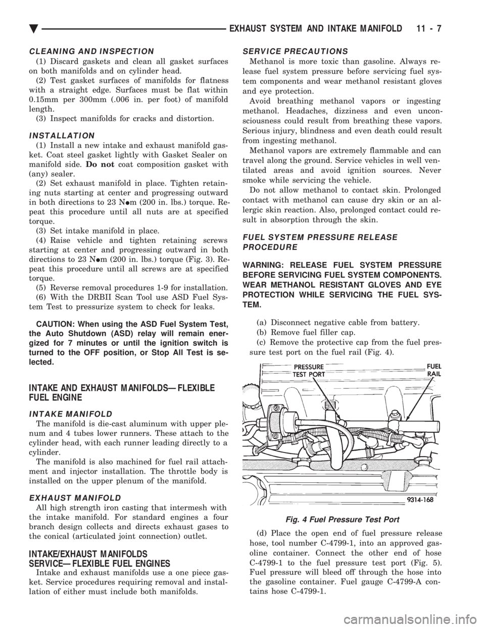
(c) Remove the protective cap from the fuel pres-
sure test port on the fuel rail (Fig. 4).
(d) Place the open end of fuel pressure release
hose, tool number C-4799-1, into an approved gas-
oline container. Connect the other end of hose
C-4799-1 to the fuel pressure test port (Fig. 5).
Fuel pressure will bleed off through the hose into
the gasoline container. Fuel gauge C-4799-A con-
tains hose C-4799-1.
Fig. 4 Fuel Pressure Test Port
Ä EXHAUST SYSTEM AND INTAKE MANIFOLD 11 - 7
Page 1705 of 2438
EXHAUST MANIFOLD
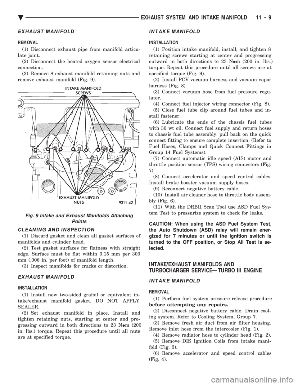
REMOVAL (1) Disconnect exhaust pipe from manifold articu-
late joint. (2) Disconnect the heated oxygen sensor electrical
connection. (3) Remove 8 exhaust manifold retaining nuts and
remove exhaust manifold (Fig. 9).
CLEANING AND INSPECTION
(1) Discard gasket and clean all gasket surfaces of
manifolds and cylinder head. (2) Test gasket surfaces for flatness with straight
edge. Surface must be flat within 0.15 mm per 300
mm (.006 in. per foot) of manifold length. (3) Inspect manifolds for cracks or distortion.
EXHAUST MANIFOLD
INSTALLATION
(1) Install new two-sided grafoil or equivalent in-
take/exhaust manifold gasket. DO NOT APPLY
SEALER. (2) Set exhaust manifold in place. Install and
tighten retaining nuts, starting at center and pro-
gressing outward in both directions to 23 N Im (200
in. lbs.) torque. Repeat this procedure until all nuts
are at specified torque.
INTAKE MANIFOLD
INSTALLATION
(1) Position intake manifold, install, and tighten 8
retaining screws starting at center and progressing
outward in both directions to 23 N Im (200 in. lbs.)
torque. Repeat this procedure until all screws are at
specified torque (Fig. 9). (2) Install PCV vacuum harness and vacuum vapor
harness (Fig. 8). (3) Connect vacuum hose from fuel pressure regu-
lator. (4) Connect fuel injector wiring connector (Fig. 8).
(5) Close fuel tube clip around fuel tubes and in-
stall fastener. (6) Lubricate the ends of the chassis fuel tubes
with 30 wt oil. Connect fuel supply and return hoses
to chassis fuel tube assembly. pull back on the quick
connect fitting to ensure complete insertion. (Refer to
Fuel Hoses, Clamps and Quick Connect Fittings in
Group 14 Fuel Systems). (7) Connect automatic idle speed (AIS) motor and
throttle position sensor (TPS) wiring connectors (Fig.
7). (8) Connect accelerator and speed control cables.
Install brake booster vacuum supply hoses. (9) Reconnect negative battery cable.
(10) Install air cleaner hose to throttle body assem-
bly (Fig. 6). (11) With the DRBII Scan Tool use ASD Fuel Sys-
tem Test to pressurize system to check for leaks.
CAUTION: When using the ASD Fuel System Test,
the Auto Shutdown (ASD) relay will remain ener-
gized for 7 minutes or until the ignition switch is
turned to the OFF position, or Stop All Test is se-
lected.
INTAKE/EXHAUST MANIFOLDS AND
TURBOCHARGER SERVICEÐTURBO III ENGINE
INTAKE MANIFOLD
REMOVAL
(1) Perform fuel system pressure release procedure
before attempting any repairs. (2) Disconnect negative battery cable. Drain cool-
ing system. Refer to Cooling System, Group 7. (3) Remove fresh air duct from air filter housing.
Remove inlet hose from the intercooler (Fig. 1). (4) Remove radiator hose to cylinder head (Fig. 2).
(5) Remove DIS Ignition Coils from intake mani-
fold (Fig. 3). (6) Remove accelerator and speed control cables
(Fig. 4).
Fig. 9 Intake and Exhaust Manifolds Attaching Points
Ä EXHAUST SYSTEM AND INTAKE MANIFOLD 11 - 9