1993 CHEVROLET PLYMOUTH ACCLAIM length
[x] Cancel search: lengthPage 1624 of 2438
OIL PAN
A formed steel oil pan provides lower engine pro-
tection as well as serving as the engine oil reservoir
(Fig. 1). Pan side flanges to block are sealed with
gaskets. The oil pickup tube for some 2.2L engines
have a circular strainer and cover. The 2.5L engine
pickup is also unsupported and the lower end has a
box type strainer (Fig. 4).
PRESSURE LUBRICATION
Oil drawn up through the pickup tube is pressur-
ized by the pump and routed through the full flow
filter to the main oil gallery running the length of
the cylinder block (Fig. 2). Modified oil pickup, pump
and check valve provide increased oil flow to the
main oil gallery.
MAIN/ROD BEARINGS
A diagonal hole in each bulkhead feeds oil to each
main bearing. Drilled passages within the crankshaft
route oil from main bearing journals to crankpin
journals.
ACCESSORY SHAFT
Two separate holes supply the accessory shaft for
the N/A engines. For Turbo III engines there is a slot
in the rear shaft bushing that squirts oil onto the
oil pump drive gears (Fig. 2).
BALANCE SHAFTS
The engine balance shafts are lubricated by an ad-
ditional hole that interconnects a passage in one leg
of the balance shaft carrier to route oil down to the
carrier oil gallery. This gallery directly supplies the
balance shafts front bearings and internal machined
passages in the shafts routes oil from front to rear
shaft bearing journals.
TURBOCHARGER (WHERE EQUIPPED)
If turbocharger equipped, pressurized oil from the
main gallery to sending unit hex fitting is piped from
the fitting to the turbocharger bearing housing.
From the housing a hose and tube connection to a
machined hole in the block provides drainback.
CAMSHAFT/HYDRAULIC LIFTERS
A vertical hole at the number five bulkhead routes
pressurized oil through a restrictor up past a cylinder
head bolt to an oil gallery running the length of the
cylinder head. For 2.2/2.5L and 2.5L FFV engines
hydraulic adjusters are supplied directly from this
gallery while diagonal holes supply oil to the cam-
shaft journals. The camshaft journals are partially
slotted to allow a predetermined amount of pressur-
ized oil to pass into the bearing cap cavities with
small holes directed to spray lubricate the camshaft
lobes. For Turbo III engines oil is supplied thru oil
galleries in the head to the camshafts and rocker arm shafts which feed oil to the lash adjusters. Oil is
feed thru the rocker arms to lubricate the rollers and
the camshaft lobes.
SPLASH LUBRICATION
Oil returning to the pan from pressurized compo-
nents supplies lubrication to the valve stems. Cylinder
bores and wrist pins are splash lubricated from di-
rected holes in the connecting rods.
OIL PAN
REMOVAL
(1) Drain engine oil and remove oil pan.
(2) Clean oil pan and all gasket surfaces.
OIL PAN RAIL TO BLOCK SEALING
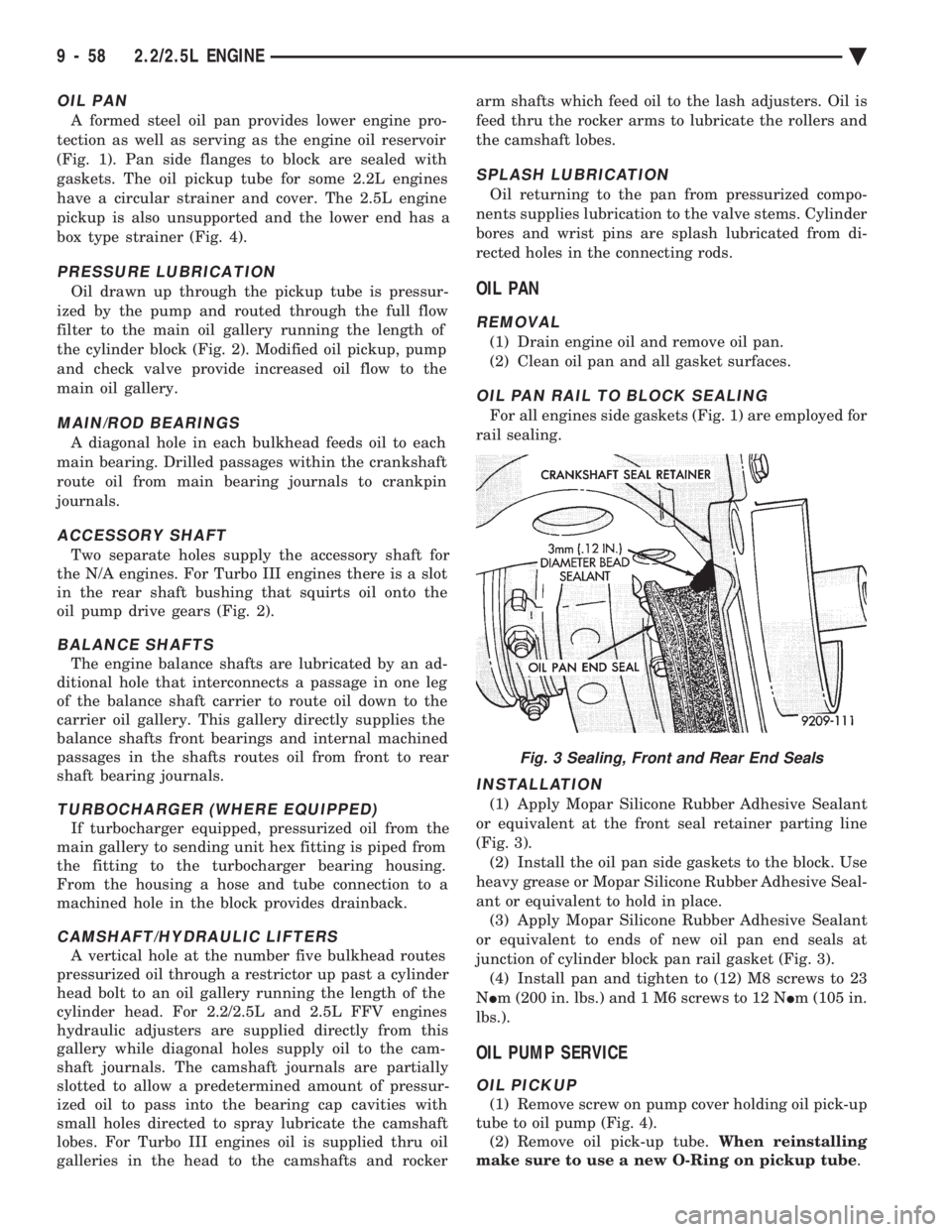
For all engines side gaskets (Fig. 1) are employed for
rail sealing.
INSTALLATION
(1) Apply Mopar Silicone Rubber Adhesive Sealant
or equivalent at the front seal retainer parting line
(Fig. 3). (2) Install the oil pan side gaskets to the block. Use
heavy grease or Mopar Silicone Rubber Adhesive Seal-
ant or equivalent to hold in place. (3) Apply Mopar Silicone Rubber Adhesive Sealant
or equivalent to ends of new oil pan end seals at
junction of cylinder block pan rail gasket (Fig. 3). (4) Install pan and tighten to (12) M8 screws to 23
N Im (200 in. lbs.) and 1 M6 screws to 12 N Im (105 in.
lbs.).
OIL PUMP SERVICE
OIL PICKUP
(1) Remove screw on pump cover holding oil pick-up
tube to oil pump (Fig. 4). (2) Remove oil pick-up tube. When reinstalling
make sure to use a new O-Ring on pickup tube .
Fig. 3 Sealing, Front and Rear End Seals
9 - 58 2.2/2.5L ENGINE Ä
Page 1626 of 2438
CAUTION: Pump must be held in fully seated posi-
tion (described above) while installing screws. (6) Tighten screws to 23 N Im (200 in. lbs.).
INSPECTION
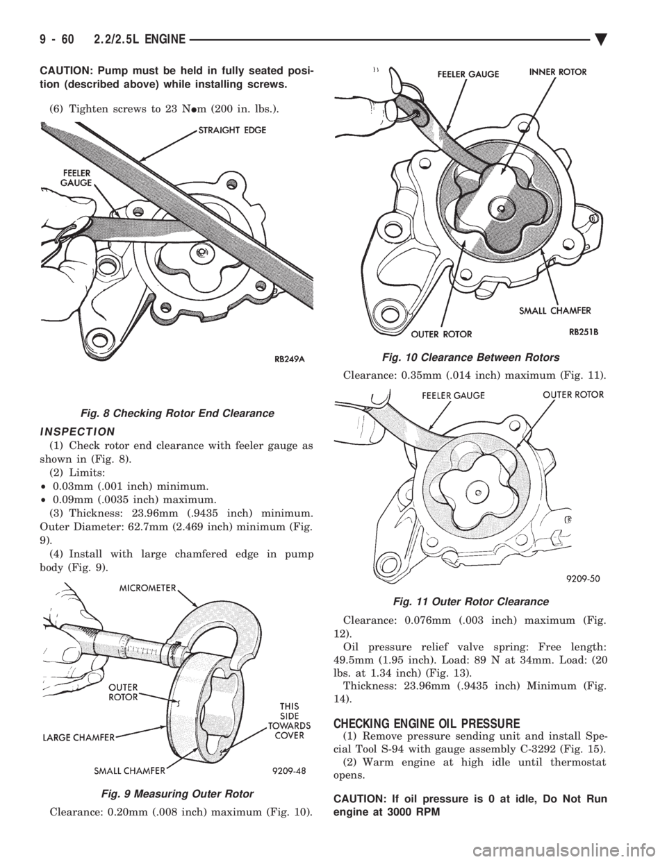
(1) Check rotor end clearance with feeler gauge as
shown in (Fig. 8). (2) Limits:
² 0.03mm (.001 inch) minimum.
² 0.09mm (.0035 inch) maximum.
(3) Thickness: 23.96mm (.9435 inch) minimum.
Outer Diameter: 62.7mm (2.469 inch) minimum (Fig.
9). (4) Install with large chamfered edge in pump
body (Fig. 9).
Clearance: 0.20mm (.008 inch) maximum (Fig. 10). Clearance: 0.35mm (.014 inch) maximum (Fig. 11).
Clearance: 0.076mm (.003 inch) maximum (Fig.
12). Oil pressure relief valve spring: Free length:
49.5mm (1.95 inch). Load: 89 N at 34mm. Load: (20
lbs. at 1.34 inch) (Fig. 13). Thickness: 23.96mm (.9435 inch) Minimum (Fig.
14).
CHECKING ENGINE OIL PRESSURE
(1) Remove pressure sending unit and install Spe-
cial Tool S-94 with gauge assembly C-3292 (Fig. 15). (2) Warm engine at high idle until thermostat
opens.
CAUTION: If oil pressure is 0 at idle, Do Not Run
engine at 3000 RPM
Fig. 8 Checking Rotor End Clearance
Fig. 9 Measuring Outer Rotor
Fig. 10 Clearance Between Rotors
Fig. 11 Outer Rotor Clearance
9 - 60 2.2/2.5L ENGINE Ä
Page 1632 of 2438
3.0L ENGINE INDEX
page page
Accessory Drive Belt Service ................ 70
Auto Lash Adjuster ....................... 75
Camshaft Service ........................ 76
Checking Engine Oil Pressure ............... 93
Crankshaft and Cylinder Block, Assembly Service . 86
Cylinder Block ........................... 89
Cylinder Head ........................... 78
Cylinder Head and Camshaft Service ......... 75
Engine Assembly ......................... 69
Engine Lubrication System ................. 91
Engine Mounts .......................... 68 Engine Specifications
..................... 95
General Information ....................... 66
Oil Filter and Bracket ..................... 94
Oil Pan ................................ 92
Oil Pump Service ........................ 92
Piston and Connecting Rod Assembly Service . . . 82
Timing Belt InspectionÐIn Vehicle ............ 72
Timing Belt Service ....................... 72
Valve Service ........................... 80
GENERAL INFORMATION
ENGINE IDENTIFICATION NUMBER OR CODE
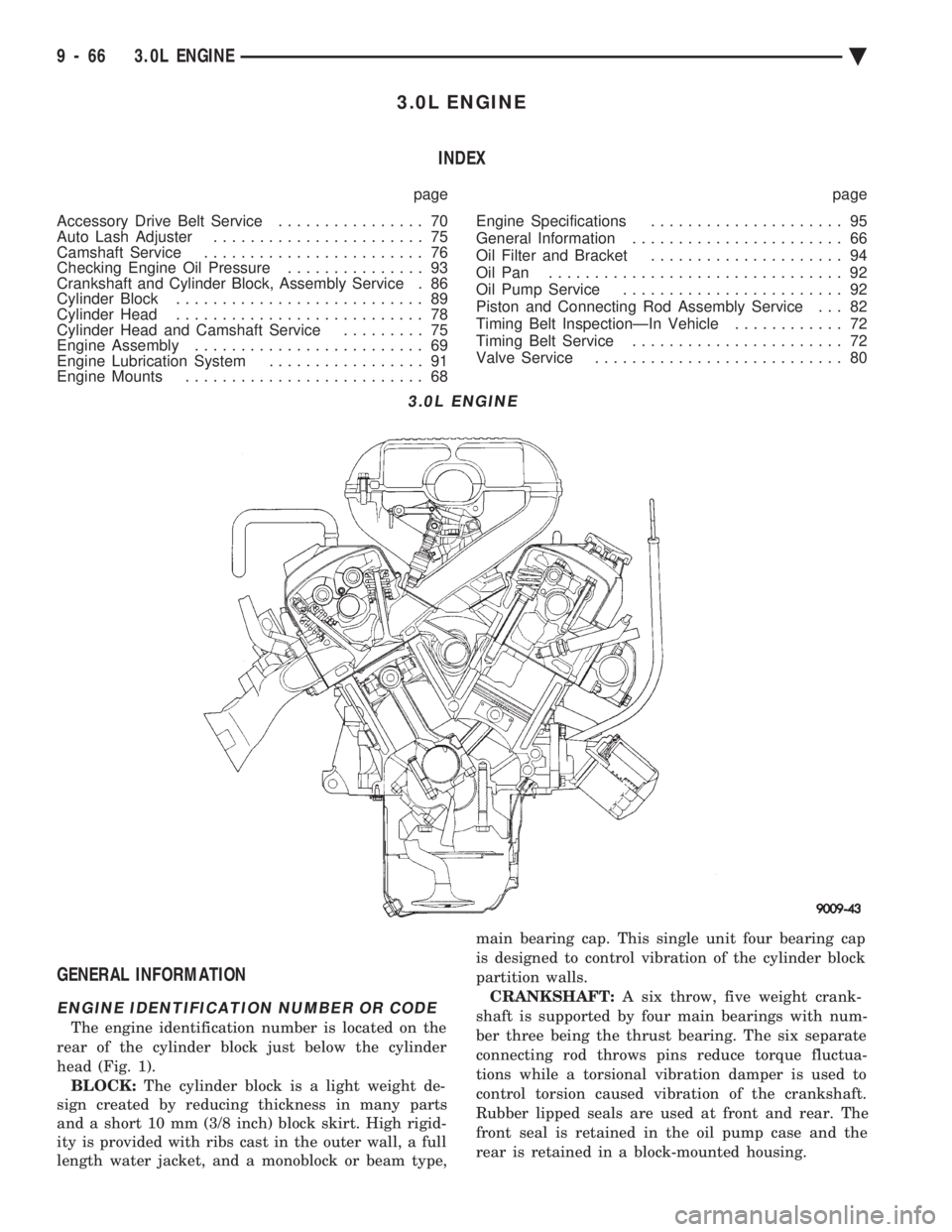
The engine identification number is located on the
rear of the cylinder block just below the cylinder
head (Fig. 1). BLOCK: The cylinder block is a light weight de-
sign created by reducing thickness in many parts
and a short 10 mm (3/8 inch) block skirt. High rigid-
ity is provided with ribs cast in the outer wall, a full
length water jacket, and a monoblock or beam type, main bearing cap. This single unit four bearing cap
is designed to control vibration of the cylinder block
partition walls.
CRANKSHAFT: A six throw, five weight crank-
shaft is supported by four main bearings with num-
ber three being the thrust bearing. The six separate
connecting rod throws pins reduce torque fluctua-
tions while a torsional vibration damper is used to
control torsion caused vibration of the crankshaft.
Rubber lipped seals are used at front and rear. The
front seal is retained in the oil pump case and the
rear is retained in a block-mounted housing.
3.0L ENGINE
9 - 66 3.0L ENGINE Ä
Page 1635 of 2438
LEFT SIDE MOUNT
(1) Raise vehicle on hoist and remove left front
wheel. (2) Remove inter splash shield.
(3) Support the transmission with a transmission
jack. (4) Remove the insulator thru bolt from the mount.
(5) Remove the transmission mount fasteners and
remove mount. (6) Reverse removal procedure for installation. En-
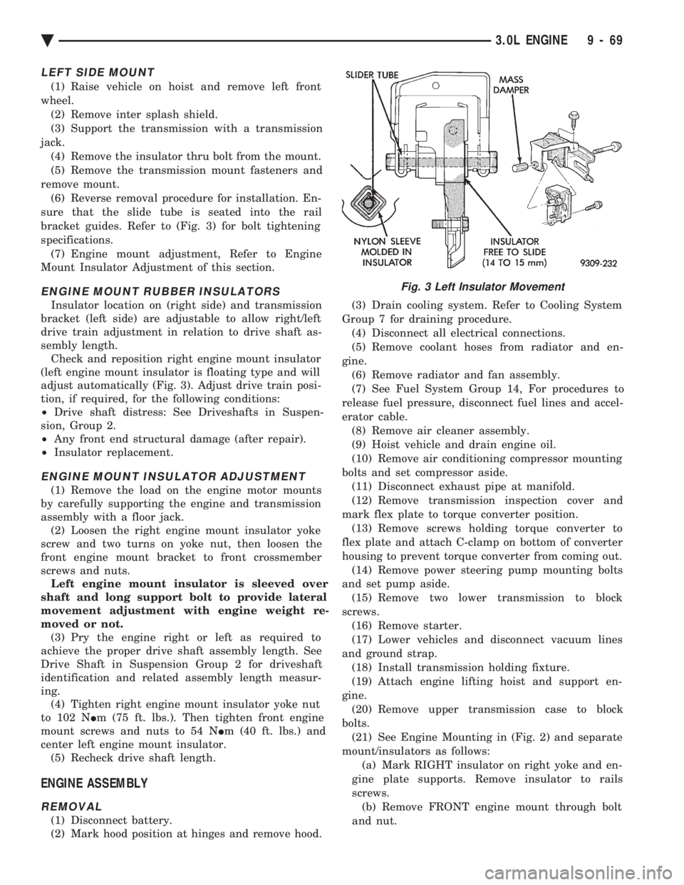
sure that the slide tube is seated into the rail
bracket guides. Refer to (Fig. 3) for bolt tightening
specifications. (7) Engine mount adjustment, Refer to Engine
Mount Insulator Adjustment of this section.
ENGINE MOUNT RUBBER INSULATORS
Insulator location on (right side) and transmission
bracket (left side) are adjustable to allow right/left
drive train adjustment in relation to drive shaft as-
sembly length. Check and reposition right engine mount insulator
(left engine mount insulator is floating type and will
adjust automatically (Fig. 3). Adjust drive train posi-
tion, if required, for the following conditions:
² Drive shaft distress: See Driveshafts in Suspen-
sion, Group 2.
² Any front end structural damage (after repair).
² Insulator replacement.
ENGINE MOUNT INSULATOR ADJUSTMENT
(1) Remove the load on the engine motor mounts
by carefully supporting the engine and transmission
assembly with a floor jack. (2) Loosen the right engine mount insulator yoke
screw and two turns on yoke nut, then loosen the
front engine mount bracket to front crossmember
screws and nuts. Left engine mount insulator is sleeved over
shaft and long support bolt to provide lateral
movement adjustment with engine weight re-
moved or not. (3) Pry the engine right or left as required to
achieve the proper drive shaft assembly length. See
Drive Shaft in Suspension Group 2 for driveshaft
identification and related assembly length measur-
ing. (4) Tighten right engine mount insulator yoke nut
to 102 N Im (75 ft. lbs.). Then tighten front engine
mount screws and nuts to 54 N Im (40 ft. lbs.) and
center left engine mount insulator. (5) Recheck drive shaft length.
ENGINE ASSEMBLY
REMOVAL
(1) Disconnect battery.
(2) Mark hood position at hinges and remove hood. (3) Drain cooling system. Refer to Cooling System
Group 7 for draining procedure. (4) Disconnect all electrical connections.
(5) Remove coolant hoses from radiator and en-
gine. (6) Remove radiator and fan assembly.
(7) See Fuel System Group 14, For procedures to
release fuel pressure, disconnect fuel lines and accel-
erator cable. (8) Remove air cleaner assembly.
(9) Hoist vehicle and drain engine oil.
(10) Remove air conditioning compressor mounting
bolts and set compressor aside. (11) Disconnect exhaust pipe at manifold.
(12) Remove transmission inspection cover and
mark flex plate to torque converter position. (13) Remove screws holding torque converter to
flex plate and attach C-clamp on bottom of converter
housing to prevent torque converter from coming out. (14) Remove power steering pump mounting bolts
and set pump aside. (15) Remove two lower transmission to block
screws. (16) Remove starter.
(17) Lower vehicles and disconnect vacuum lines
and ground strap. (18) Install transmission holding fixture.
(19) Attach engine lifting hoist and support en-
gine. (20) Remove upper transmission case to block
bolts. (21) See Engine Mounting in (Fig. 2) and separate
mount/insulators as follows: (a) Mark RIGHT insulator on right yoke and en-
gine plate supports. Remove insulator to rails
screws. (b) Remove FRONT engine mount through bolt
and nut.
Fig. 3 Left Insulator Movement
Ä 3.0L ENGINE 9 - 69
Page 1646 of 2438
INSTALLATION
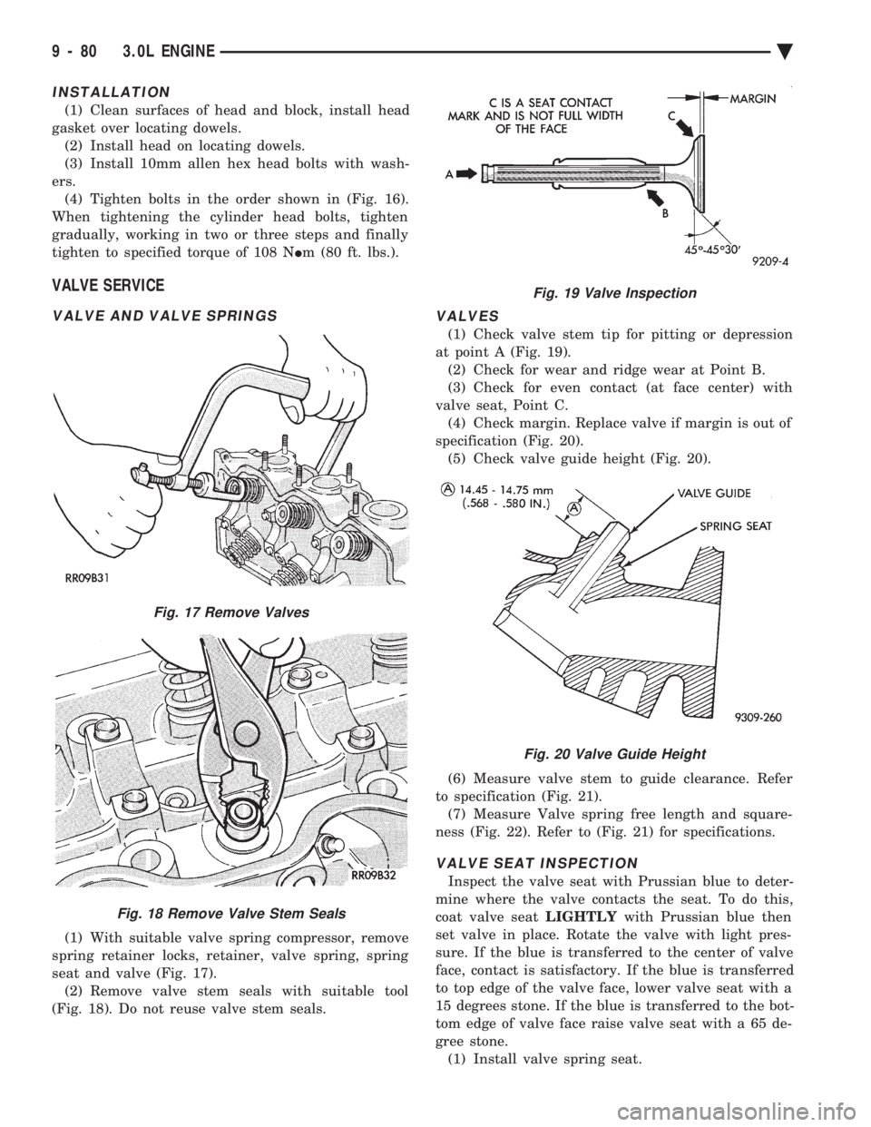
(1) Clean surfaces of head and block, install head
gasket over locating dowels. (2) Install head on locating dowels.
(3) Install 10mm allen hex head bolts with wash-
ers. (4) Tighten bolts in the order shown in (Fig. 16).
When tightening the cylinder head bolts, tighten
gradually, working in two or three steps and finally
tighten to specified torque of 108 N Im (80 ft. lbs.).
VALVE SERVICE
VALVE AND VALVE SPRINGS
(1) With suitable valve spring compressor, remove
spring retainer locks, retainer, valve spring, spring
seat and valve (Fig. 17). (2) Remove valve stem seals with suitable tool
(Fig. 18). Do not reuse valve stem seals.
VALVES
(1) Check valve stem tip for pitting or depression
at point A (Fig. 19). (2) Check for wear and ridge wear at Point B.
(3) Check for even contact (at face center) with
valve seat, Point C. (4) Check margin. Replace valve if margin is out of
specification (Fig. 20). (5) Check valve guide height (Fig. 20).
(6) Measure valve stem to guide clearance. Refer
to specification (Fig. 21). (7) Measure Valve spring free length and square-
ness (Fig. 22). Refer to (Fig. 21) for specifications.
VALVE SEAT INSPECTION
Inspect the valve seat with Prussian blue to deter-
mine where the valve contacts the seat. To do this,
coat valve seat LIGHTLYwith Prussian blue then
set valve in place. Rotate the valve with light pres-
sure. If the blue is transferred to the center of valve
face, contact is satisfactory. If the blue is transferred
to top edge of the valve face, lower valve seat with a
15 degrees stone. If the blue is transferred to the bot-
tom edge of valve face raise valve seat with a 65 de-
gree stone. (1) Install valve spring seat.
Fig. 17 Remove Valves
Fig. 18 Remove Valve Stem Seals
Fig. 19 Valve Inspection
Fig. 20 Valve Guide Height
9 - 80 3.0L ENGINE Ä
Page 1653 of 2438
PLASTIGAGE MEASUREMENT
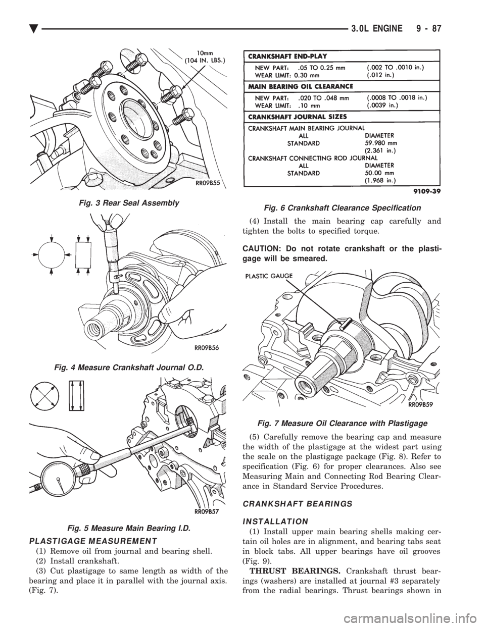
(1) Remove oil from journal and bearing shell.
(2) Install crankshaft.
(3) Cut plastigage to same length as width of the
bearing and place it in parallel with the journal axis.
(Fig. 7). (4) Install the main bearing cap carefully and
tighten the bolts to specified torque.
CAUTION: Do not rotate crankshaft or the plasti-
gage will be smeared.
(5) Carefully remove the bearing cap and measure
the width of the plastigage at the widest part using
the scale on the plastigage package (Fig. 8). Refer to
specification (Fig. 6) for proper clearances. Also see
Measuring Main and Connecting Rod Bearing Clear-
ance in Standard Service Procedures.
CRANKSHAFT BEARINGS
INSTALLATION
(1) Install upper main bearing shells making cer-
tain oil holes are in alignment, and bearing tabs seat
in block tabs. All upper bearings have oil grooves
(Fig. 9). THRUST BEARINGS. Crankshaft thrust bear-
ings (washers) are installed at journal #3 separately
from the radial bearings. Thrust bearings shown in
Fig. 3 Rear Seal Assembly
Fig. 4 Measure Crankshaft Journal O.D.
Fig. 5 Measure Main Bearing I.D.
Fig. 6 Crankshaft Clearance Specification
Fig. 7 Measure Oil Clearance with Plastigage
Ä 3.0L ENGINE 9 - 87
Page 1655 of 2438
(3) Apply light coating of engine oil to the entire
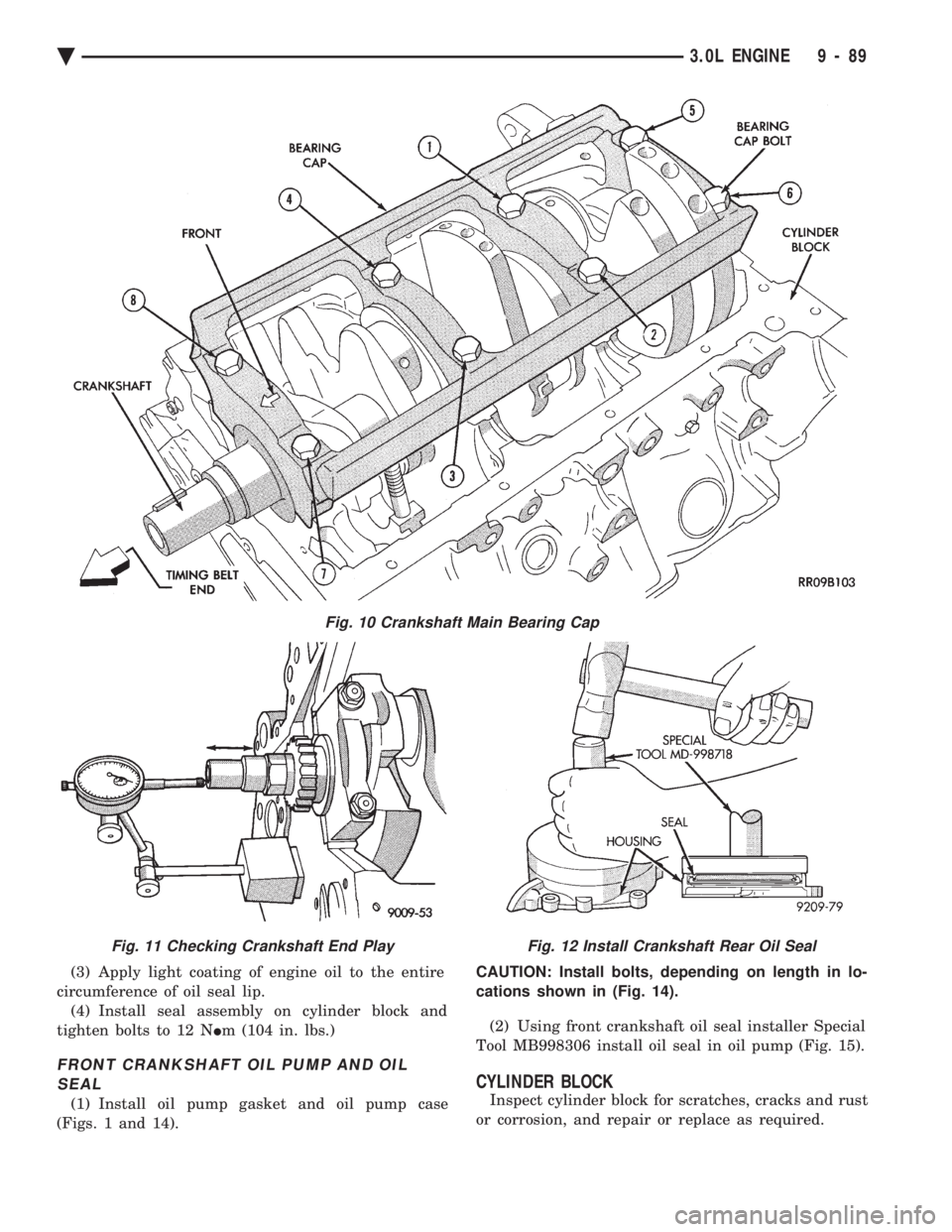
circumference of oil seal lip. (4) Install seal assembly on cylinder block and
tighten bolts to 12 N Im (104 in. lbs.)
FRONT CRANKSHAFT OIL PUMP AND OIL
SEAL
(1) Install oil pump gasket and oil pump case
(Figs. 1 and 14). CAUTION: Install bolts, depending on length in lo-
cations shown in (Fig. 14).
(2) Using front crankshaft oil seal installer Special
Tool MB998306 install oil seal in oil pump (Fig. 15).
CYLINDER BLOCK
Inspect cylinder block for scratches, cracks and rust
or corrosion, and repair or replace as required.
Fig. 10 Crankshaft Main Bearing Cap
Fig. 11 Checking Crankshaft End PlayFig. 12 Install Crankshaft Rear Oil Seal
Ä 3.0L ENGINE 9 - 89
Page 1659 of 2438
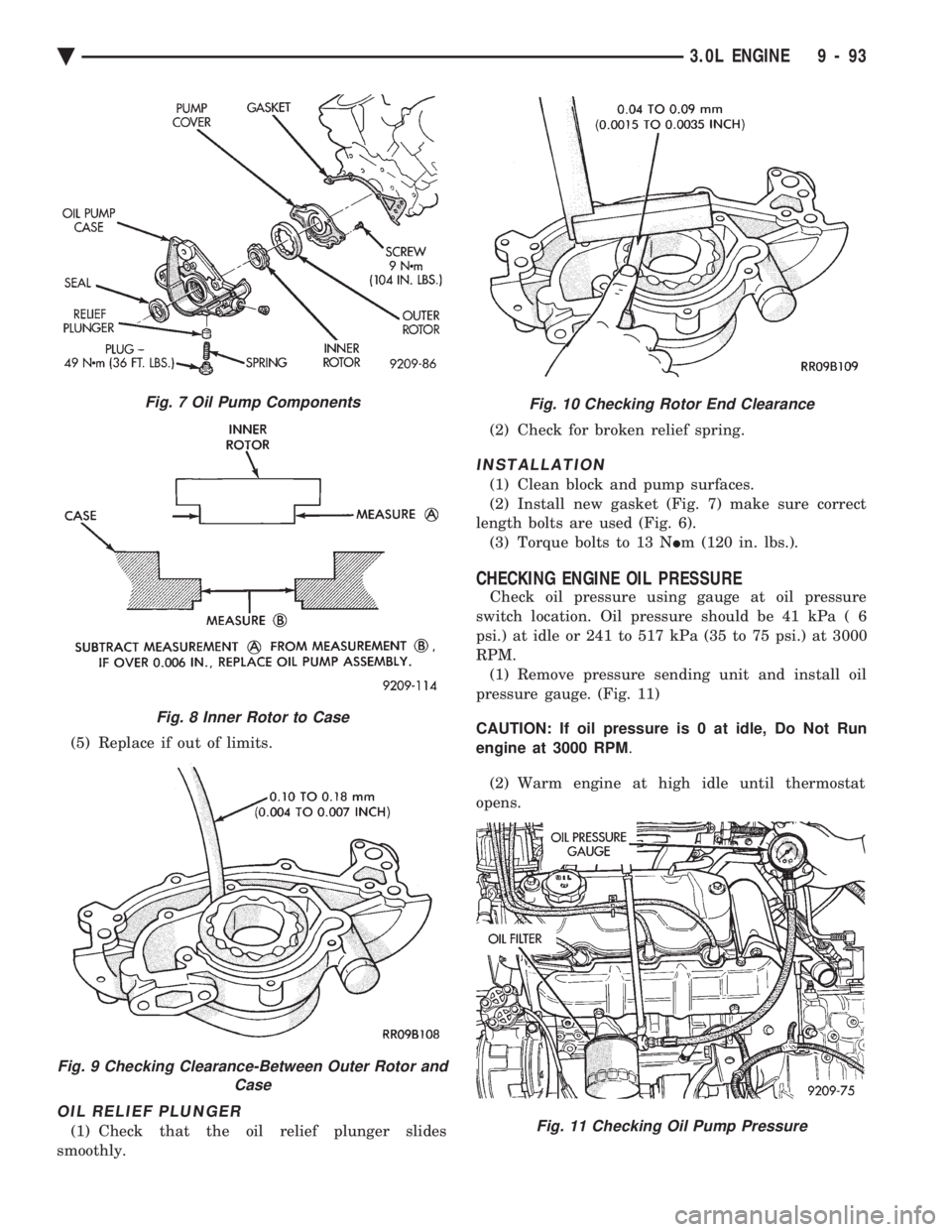
(5) Replace if out of limits.
OIL RELIEF PLUNGER
(1) Check that the oil relief plunger slides
smoothly. (2) Check for broken relief spring.
INSTALLATION
(1) Clean block and pump surfaces.
(2) Install new gasket (Fig. 7) make sure correct
length bolts are used (Fig. 6). (3) Torque bolts to 13 N Im (120 in. lbs.).
CHECKING ENGINE OIL PRESSURE
Check oil pressure using gauge at oil pressure
switch location. Oil pressure should be 41 kPa ( 6
psi.) at idle or 241 to 517 kPa (35 to 75 psi.) at 3000
RPM. (1) Remove pressure sending unit and install oil
pressure gauge. (Fig. 11)
CAUTION: If oil pressure is 0 at idle, Do Not Run
engine at 3000 RPM .
(2) Warm engine at high idle until thermostat
opens.
Fig. 7 Oil Pump Components
Fig. 8 Inner Rotor to Case
Fig. 9 Checking Clearance-Between Outer Rotor and Case
Fig. 10 Checking Rotor End Clearance
Fig. 11 Checking Oil Pump Pressure
Ä 3.0L ENGINE 9 - 93