1993 CHEVROLET PLYMOUTH ACCLAIM length
[x] Cancel search: lengthPage 1709 of 2438
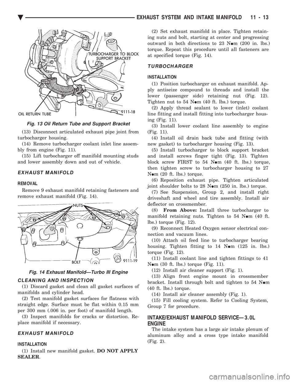
(13) Disconnect articulated exhaust pipe joint from
turbocharger housing. (14) Remove turbocharger coolant inlet line assem-
bly from engine (Fig. 11). (15) Lift turbocharger off manifold mounting studs
and lower assembly down and out of vehicle.
EXHAUST MANIFOLD
REMOVAL
Remove 9 exhaust manifold retaining fasteners and
remove exhaust manifold (Fig. 14).
CLEANING AND INSPECTION
(1) Discard gasket and clean all gasket surfaces of
manifolds and cylinder head. (2) Test manifold gasket surfaces for flatness with
straight edge. Surface must be flat within 0.15 mm
per 300 mm (.006 in. per foot) of manifold length. (3) Inspect manifolds for cracks or distortion. Re-
place manifold if necessary.
EXHAUST MANIFOLD
INSTALLATION
(1) Install new manifold gasket. DO NOT APPLY
SEALER . (2) Set exhaust manifold in place. Tighten retain-
ing nuts and bolt, starting at center and progressing
outward in both directions to 23 N Im (200 in. lbs.)
torque. Repeat this procedure until all fasteners are
at specified torque (Fig. 14).
TURBOCHARGER
INSTALLATION
(1) Position turbocharger on exhaust manifold. Ap-
ply antiseize compound to threads and install the
lower (passenger side) retaining nut (Fig. 12).
Tighten nut to 54 N Im (40 ft. lbs.) torque.
(2) Apply thread sealant to lower (inlet) coolant
line fitting and install fitting into turbocharger hous-
ing (Fig. 11). (3) Install lower coolant line assembly to engine
(Fig. 11). (4) Install oil drain back tube and fitting (with
new gasket) to turbocharger housing (Fig. 13). (5) Install turbocharger to block support bracket
and install screws finger tight (Fig. 13). Tighten
block screw FIRST to 54 N Im (40 ft. lbs.) torque,
then tighten screw to turbocharger housing to 27
N Im (20 ft. lbs.) torque.
(6) Reposition exhaust pipe. Tighten articulated
joint shoulder bolts to 28 N Im (250 in. lbs.) torque.
(7) See Suspension, Group 2, and install right
driveshaft and wheel and tire assembly. Install air
deflector on crossmember. (8) From Above: Install three turbocharger to
manifold retaining nuts. Tighten to 54 N Im (40 ft.
lbs.) torque (Fig. 12). (9) Reconnect Heated Oxygen sensor electrical con-
nection and vacuum lines. (10) Attach oil feed line to turbocharger bearing
housing. Tighten fitting to 14 N Im (125 in. lbs.)
torque (Fig. 12). (11) Install coolant line and tighten fittings to 41
N Im (30 ft. lbs.) torque (Fig. 11).
(12) Install air cleaner support (Fig. 1).
(13) Align front engine mount in crossmember
bracket. Install through bolt and tighten to 54 N Im
(40 ft. lbs.) torque. (14) Install air cleaner assembly (Fig. 1).
(15) Fill cooling system. Refer to Cooling System,
Group 7 for procedure.
INTAKE/EXHAUST MANIFOLD SERVICEÐ3.0L
ENGINE
The intake system has a large air intake plenum of
aluminum alloy and a cross type intake manifold
(Fig. 2).
Fig. 13 Oil Return Tube and Support Bracket
Fig. 14 Exhaust ManifoldÐTurbo III Engine
Ä EXHAUST SYSTEM AND INTAKE MANIFOLD 11 - 13
Page 1853 of 2438
3.0L MULTI-PORT FUEL INJECTIONÐSYSTEM OPERATION INDEX
page page
Air Conditioning (A/C) Clutch Relay (AA, AG, AJ Body)ÐPCM Output .................... 118
Air Conditioning (A/C) Clutch Relay (AC Body) ÐPCM Output ........................ 118
Air Conditioning Switch Sense (AA, AG, AJ Body)ÐPCM Input ..................... 115
Air Conditioning Switch Sense (AC Body)ÐPCM Input ................................ 115
Auto Shutdown (ASD) Relay and Fuel Pump RelayÐPCM Output .................... 119
Battery VoltageÐPCM Input ............... 115
Brake SwitchÐPCM Input ................. 115
CCD Bus .............................. 113
Data Link ConnectorÐPCM Output .......... 120
Distributor Pick-UpÐPCM Input ............. 115
Duty Cycle Evap Canister Purge Solenoid ÐPCM Output ........................ 119
Engine Coolant Temperature Sensor ÐPCM Input ......................... 115
Fuel InjectorsÐPCM Output ............... 120
Fuel Pressure Regulator .................. 124
Fuel Supply Circuit ...................... 123
General Information ...................... 113 Generator FieldÐPCM Output
.............. 118
Heated Oxygen Sensor (O
2Sensor)
ÐPCM Input ......................... 116
Idle Air Control MotorÐPCM Output ......... 119
Ignition CoilÐPCM Output ................. 121
Malfunction Indicator Lamp (Check Engine Lamp)ÐPCM Output ................... 120
Manifold Absolute Pressure (MAP) Sensor ÐPCM Input ......................... 116
Modes of Operation ...................... 121
Park/Neutral SwitchÐPCM Input ............ 117
Part Throttle Unlock SolenoidÐPCM Output . . . 121
Powertrain Control Module ................. 113
Radiator Fan RelayÐPCM Output ........... 121
Speed Control SolenoidsÐPCM Output ....... 121
Speed ControlÐPCM Input ................ 117
System Diagnosis ....................... 113
TachometerÐPCM Output ................. 121
Throttle Body ........................... 123
Throttle Position Sensor (TPS)ÐPCM Input .... 117
Transaxle Control ModuleÐPCM Output ...... 120
Vehicle Speed and Distance InputÐPCM Input . 118
Vehicle Speed SensorÐPCM Input .......... 118
GENERAL INFORMATION
The 3.0L engine uses a sequential Multi-Port Elec-
tronic Fuel Injection system (Fig. 1). The MPI system
is computer regulated and provides precise air/fuel
ratios for all driving conditions. The MPI system is operated by the powertrain con-
trol module (PCM). The PCM regulates ignition timing, air-fuel ratio,
emission control devices, cooling fan, charging sys-
tem, idle speed and speed control. Various sensors
provide the inputs necessary for the PCM to correctly
operate these systems. In addition to the sensors,
various switches also provide inputs to the PCM. All inputs to the PCM are converted into signals.
The PCM can adapt its programming to meet chang-
ing operating conditions. Fuel is injected into the intake port above the in-
take valve in precise metered amounts through elec-
trically operated injectors. The PCM fires the
injectors in a specific sequence. The PCM maintains
an air fuel ratio of 14.7 parts air to 1 part fuel by
constantly adjusting injector pulse width. Injector
pulse width is the length of time the injector is ener-
gized. The PCM adjusts injector pulse width by opening
and closing the ground path to the injector. Engine
RPM (speed) and manifold absolute pressure (air
density) are the primary inputs that determine injec-
tor pulse width.
SYSTEM DIAGNOSIS
The powertrain control module (PCM) tests many
of its own input and output circuits. If a fault is
found in a major system, the information is stored in
memory. Technicians can display fault information
through the malfunction indicator lamp (instrument
panel Check Engine lamp) or by connecting the
DRBII scan tool. For diagnostic trouble code informa-
tion, refer to the 3.0 Multi-Port Fuel InjectionÐOn-
Board Diagnostics section of this group.
CCD BUS
Various modules exchange information through a
communications port called the CCD Bus. The pow-
ertrain control module (PCM) transmits the malfunc-
tion indicator (instrument panel check engine lamp)
On/Off signal, engine RPM and vehicle load data on
the CCD Bus.
POWERTRAIN CONTROL MODULE
The powertrain control module (PCM) is a digital
computer containing a microprocessor (Fig. 2). The
PCM receives input signals from various switches
and sensors that are referred to as PCM Inputs.
Based on these inputs, the PCM adjusts various en-
gine and vehicle operations through devices referred
to as PCM Outputs. PCM Inputs:
² Air Conditioning Controls
² Battery Voltage
² Brake Switch
Ä FUEL SYSTEMS 14 - 113
Page 1886 of 2438
The PCM regulates ignition timing, air-fuel ratio,
emission control devices, cooling fan, charging sys-
tem, idle speed and speed control. Various sensors
provide the inputs necessary for the PCM to correctly
operate these systems. In addition to the sensors,
various switches also provide inputs to the PCM. All inputs to the PCM are converted into signals.
The PCM can adapt its programming to meet chang-
ing operating conditions. Fuel is injected into the intake port above the in-
take valve in precise metered amounts through elec-
trically operated injectors. The PCM fires the
injectors in a specific sequence. The PCM maintains
an air fuel ratio of 14.7 parts air to 1 part fuel by
constantly adjusting injector pulse width. Injector
pulse width is the length of time the injector is ener-
gized. The PCM adjusts injector pulse width by opening
and closing the ground path to the injector. Engine
RPM (speed) and manifold absolute pressure (air
density) are the primary inputs that determine injec-
tor pulse width.
SYSTEM DIAGNOSIS
The PCM tests many of its own input and output
circuits. If a fault is found in a major system, the in-
formation is stored in memory. Technicians can dis-
play fault information through the malfunction
indicator lamp (instrument panel Check Engine
lamp) or by connecting the DRBII scan tool. For di-
agnostic trouble code information, refer to the 3.3L/
3.8L Multi-Point Fuel InjectionÐOn-Board
Diagnostics section of this group.
CCD BUS
Various modules exchange information through a
communications port called the CCD Bus. The pow-
ertrain control module (PCM) transmits engine RPM
and vehicle load information on the CCD Bus.
POWERTRAIN CONTROL MODULE
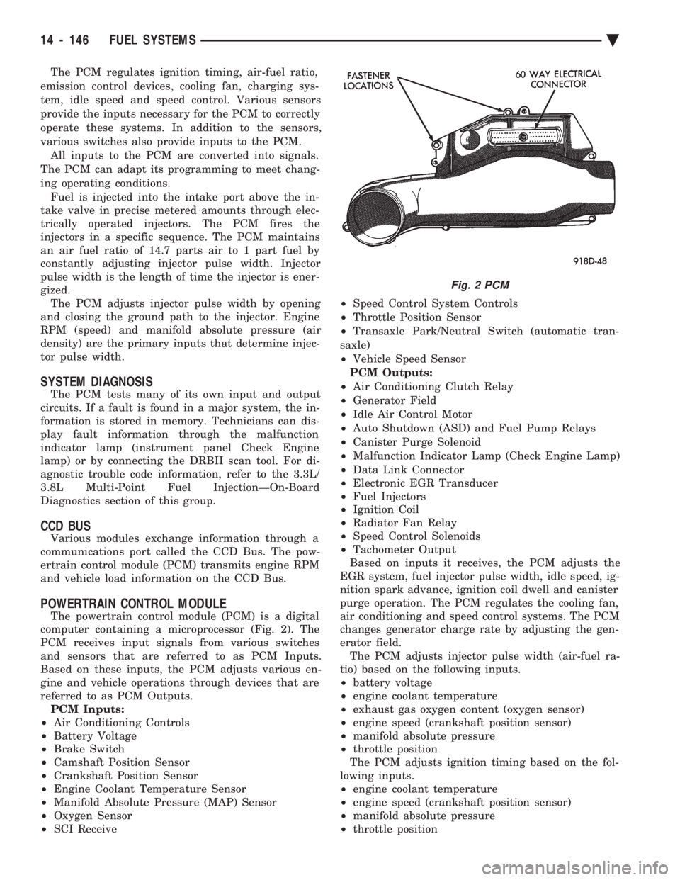
The powertrain control module (PCM) is a digital
computer containing a microprocessor (Fig. 2). The
PCM receives input signals from various switches
and sensors that are referred to as PCM Inputs.
Based on these inputs, the PCM adjusts various en-
gine and vehicle operations through devices that are
referred to as PCM Outputs. PCM Inputs:
² Air Conditioning Controls
² Battery Voltage
² Brake Switch
² Camshaft Position Sensor
² Crankshaft Position Sensor
² Engine Coolant Temperature Sensor
² Manifold Absolute Pressure (MAP) Sensor
² Oxygen Sensor
² SCI Receive ²
Speed Control System Controls
² Throttle Position Sensor
² Transaxle Park/Neutral Switch (automatic tran-
saxle)
² Vehicle Speed Sensor
PCM Outputs:
² Air Conditioning Clutch Relay
² Generator Field
² Idle Air Control Motor
² Auto Shutdown (ASD) and Fuel Pump Relays
² Canister Purge Solenoid
² Malfunction Indicator Lamp (Check Engine Lamp)
² Data Link Connector
² Electronic EGR Transducer
² Fuel Injectors
² Ignition Coil
² Radiator Fan Relay
² Speed Control Solenoids
² Tachometer Output
Based on inputs it receives, the PCM adjusts the
EGR system, fuel injector pulse width, idle speed, ig-
nition spark advance, ignition coil dwell and canister
purge operation. The PCM regulates the cooling fan,
air conditioning and speed control systems. The PCM
changes generator charge rate by adjusting the gen-
erator field. The PCM adjusts injector pulse width (air-fuel ra-
tio) based on the following inputs.
² battery voltage
² engine coolant temperature
² exhaust gas oxygen content (oxygen sensor)
² engine speed (crankshaft position sensor)
² manifold absolute pressure
² throttle position
The PCM adjusts ignition timing based on the fol-
lowing inputs.
² engine coolant temperature
² engine speed (crankshaft position sensor)
² manifold absolute pressure
² throttle position
Fig. 2 PCM
14 - 146 FUEL SYSTEMS Ä
Page 1953 of 2438
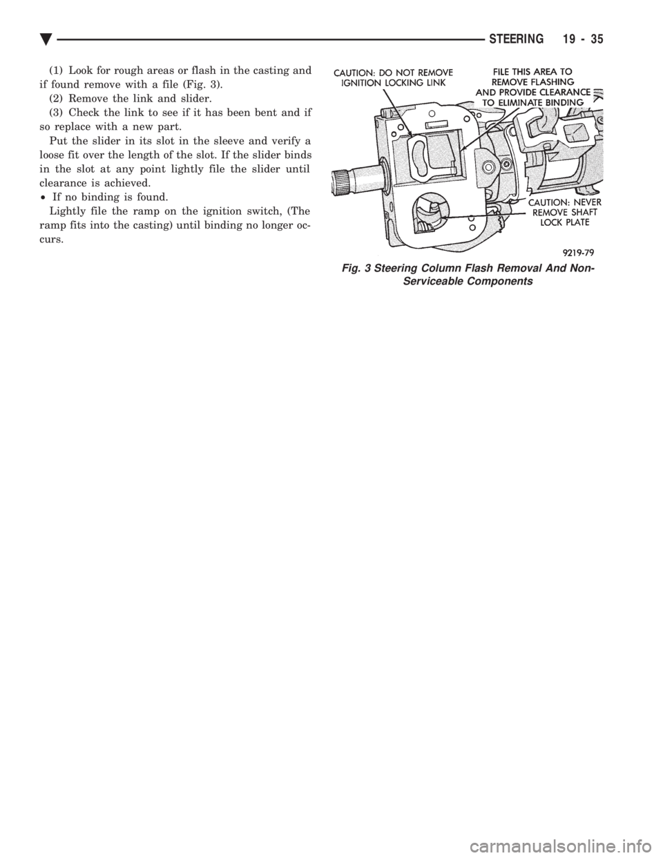
(1) Look for rough areas or flash in the casting and
if found remove with a file (Fig. 3). (2) Remove the link and slider.
(3) Check the link to see if it has been bent and if
so replace with a new part. Put the slider in its slot in the sleeve and verify a
loose fit over the length of the slot. If the slider binds
in the slot at any point lightly file the slider until
clearance is achieved.
² If no binding is found.
Lightly file the ramp on the ignition switch, (The
ramp fits into the casting) until binding no longer oc-
curs.
Fig. 3 Steering Column Flash Removal And Non- Serviceable Components
Ä STEERING 19 - 35
Page 1965 of 2438
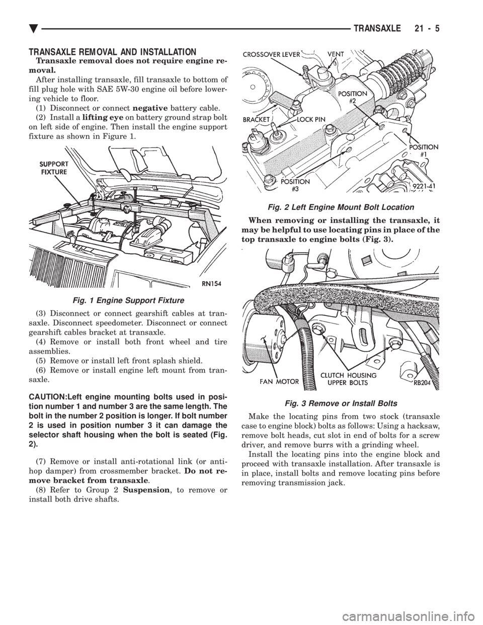
TRANSAXLE REMOVAL AND INSTALLATION
Transaxle removal does not require engine re-
moval. After installing transaxle, fill transaxle to bottom of
fill plug hole with SAE 5W-30 engine oil before lower-
ing vehicle to floor. (1) Disconnect or connect negativebattery cable.
(2) Install a lifting eyeon battery ground strap bolt
on left side of engine. Then install the engine support
fixture as shown in Figure 1.
(3) Disconnect or connect gearshift cables at tran-
saxle. Disconnect speedometer. Disconnect or connect
gearshift cables bracket at transaxle. (4) Remove or install both front wheel and tire
assemblies. (5) Remove or install left front splash shield.
(6) Remove or install engine left mount from tran-
saxle.
CAUTION:Left engine mounting bolts used in posi-
tion number 1 and number 3 are the same length. The
bolt in the number 2 position is longer. If bolt number
2 is used in position number 3 it can damage the
selector shaft housing when the bolt is seated (Fig.
2).
(7) Remove or install anti-rotational link (or anti-
hop damper) from crossmember bracket. Do not re-
move bracket from transaxle .
(8) Refer to Group 2 Suspension, to remove or
install both drive shafts. When removing or installing the transaxle, it
may be helpful to use locating pins in place of the
top transaxle to engine bolts (Fig. 3).
Make the locating pins from two stock (transaxle
case to engine block) bolts as follows: Using a hacksaw,
remove bolt heads, cut slot in end of bolts for a screw
driver, and remove burrs with a grinding wheel. Install the locating pins into the engine block and
proceed with transaxle installation. After transaxle is
in place, install bolts and remove locating pins before
removing transmission jack.
Fig. 1 Engine Support Fixture
Fig. 2 Left Engine Mount Bolt Location
Fig. 3 Remove or Install Bolts
Ä TRANSAXLE 21 - 5
Page 2158 of 2438
BODY DIAGNOSTIC PROCEDURES INDEX
page page
Water Leaks ............................. 2 Wind Noise.............................. 3
WATER LEAKS
Water leaks can be caused by poor sealing, improper
body component alignment, body seam porosity, miss-
ing plugs, or blocked drain holes. Centrifugal and
gravitational force can cause water to drip from an
area somewhat distant from the actual leak point,
making leak detection difficult. All body sealing points
should be water tight in normal wet driving conditions.
Water flowing downward from the front of the vehicle
should not enter the passenger or luggage compart-
ment. Moving sealing surfaces will not always seal
water tight under all conditions. At times, side glass,
door, or convertible top seals will allow water to enter
the passenger compartment during high pressure
washing or hard driving rain (severe) conditions. Over
compensating on door, glass, or top adjustments to stop
a water leak that occurs under severe conditions, can
cause premature seal wear and excessive closing or
latching effort. After a repair procedure has been
performed, water test vehicle to verify leak has stopped
before returning vehicle to use.
VISUAL INSPECTION BEFORE WATER LEAK TESTS
Verify that floor and body plugs are in place, body
drains are clear and body components are aligned and
sealed. If component alignment or sealing is necessary,
refer to the appropriate section of this group for proper
procedures.
WATER LEAK TESTS
WARNING: DO NOT USE ELECTRIC SHOP LIGHTS
OR TOOLS IN WATER TEST AREA, PERSONAL IN-
JURY CAN RESULT.
When a determination has been made on the condi-
tions that a water leak occurs, simulate the conditions
as closely as possible.
² If a leak occurs when the car is parked in a steady
light rain, flood the leak area with a open ended garden
hose.
² If a leak occurs at highway speeds in a steady rain,
test the leak area with a stream or fan spray of water
from a garden hose with an adjustable nozzle. Direct
the spray in the direction comparable to actual condi-
tions. ²
If a leak seems to occur only when the vehicle is
parked on an incline, hoist the end or side of the vehicle
to simulate this condition before water testing. This
method can also be used when the leak occurs when the
vehicle accelerates, stops, or turns. If the leak occurs
on acceleration, hoist the front of the vehicle. If the
leak occurs when braking, hoist the back of the vehicle.
If the leak occurs on left turns, hoist the left side of the
vehicle. If the leak occurs on right turns, hoist the right
side of the vehicle. For hoisting recommendations refer
to Group 0, Lubrication and Maintenance, General
Information section.
WATER LEAK DETECTION
To detect a water leak point of entry, perform a water
test and watch for water tracks or droplets forming on
the inside if the vehicle. If necessary remove interior
trim covers or panels to gain visual access to the leak
area. If the hose can not be positioned without being
held, have someone help perform the water test. Some water leaks must be tested for a considerable
length of time to become apparent. When a leak ap-
pears, determine the highest point of the water track or
drop. The highest point usually will indicate the point
of entry. After leak point has been determined, repair
the leak and water test to verify that leak has stopped. Locating the entry point of water that is leaking into
a cavity between panels can be difficult. The trapped
water splashes or runs from the cavity it is dammed up
in, often at a distance from the entry point. Most water
leaks of this type become apparent after accelerating,
stopping, turning, or when on a incline.
MIRROR INSPECTION METHOD
When a leak point area is visually obstructed, use a
suitable mirror to gain visual access. A mirror can also
be used to deflect light to a limited access area to assist
in locating a leak point.
BRIGHT LIGHT LEAK TEST METHOD
Some water leaks in the luggage compartment can be
detected without water testing. Position the vehicle in
a brightly light area. From inside the darkened lug-
gage compartment inspect around seals and body
seams. If necessary, have a helper direct a drop light
over the suspected leak areas around the lug-
23 - 2 BODY Ä
Page 2159 of 2438
gage compartment. If light is visible through a nor-
mally sealed location, water could enter through the
opening.
PRESSURIZED LEAK TEST METHOD
When a water leak into the passenger compartment
can not be detected by water testing, pressurize the
passenger compartment and soap test exterior of the
vehicle. To pressurize the passenger compartment,
close all doors and windows, start engine, and set
heater control to high blower in HEAT position. If
engine can not be started, connect a charger to the
battery to assure adequate voltage to the blower. With
interior pressurized, apply dish detergent solution to
suspected leak area on the exterior of the vehicle.
Apply detergent solution with spray device or soft
bristle brush. If soap bubbles occur at a body seam,
joint, seal or gasket the leak entry point could be at
that location.
WIND NOISE
Wind noise is the result of most air leaks. Air leaks
can be caused by poor sealing, improper body compo-
nent alignment, body seam porosity, or missing plugs
in the engine compartment or door hinge pillar areas.
All body sealing points should be air tight in normal
driving conditions. Moving sealing surfaces will not
always seal air tight under all conditions. At times,
side glass, door, or convertible top seals will allow wind
noise to be noticed in the passenger compartment
during high cross-winds. Over compensating on door,
glass, or top adjustments to stop wind noise that occurs
under severe conditions, can cause premature seal
wear and excessive closing or latching effort. After a repair procedure has been performed, test vehicle to
verify leak has stopped before returning vehicle to use. Wind noise can also be caused by improperly fitted
exterior mouldings or body ornamentation. Loose
mouldings can flutter, creating a buzzing or chattering
noise. An open cavity or protruding edge can create
whistling or howling noise. Inspect the exterior of the
vehicle to verify that these conditions do not exist.
VISUAL INSPECTION BEFORE TESTS
Verify that floor and body plugs are in place, body
drains are clear and body components are aligned and
sealed. If component alignment or sealing is necessary,
refer to the appropriate section of this group for proper
procedures.
ROAD TESTING WIND NOISE
(1) Drive the vehicle to verify the general location of
the wind noise. (2) Apply 50 mm (2 in.) masking tape in 150 mm (6
in.) lengths along weatherstrips, weld seams or moul-
dings. After each length is applied drive vehicle. If
noise goes away after a piece of tape is applied, remove
tape, locate and repair defect.
POSSIBLE CAUSE OF WIND NOISE
² Mouldings standing away from body surface can
catch wind and whistle.
² Gaps in sealed areas behind overhanging body
flanges can cause wind rushing sounds.
² Misaligned movable components.
² Missing or improperly installed plugs in pillars.
² Weld burn through holes.
Ä BODY 23 - 3
Page 2180 of 2438
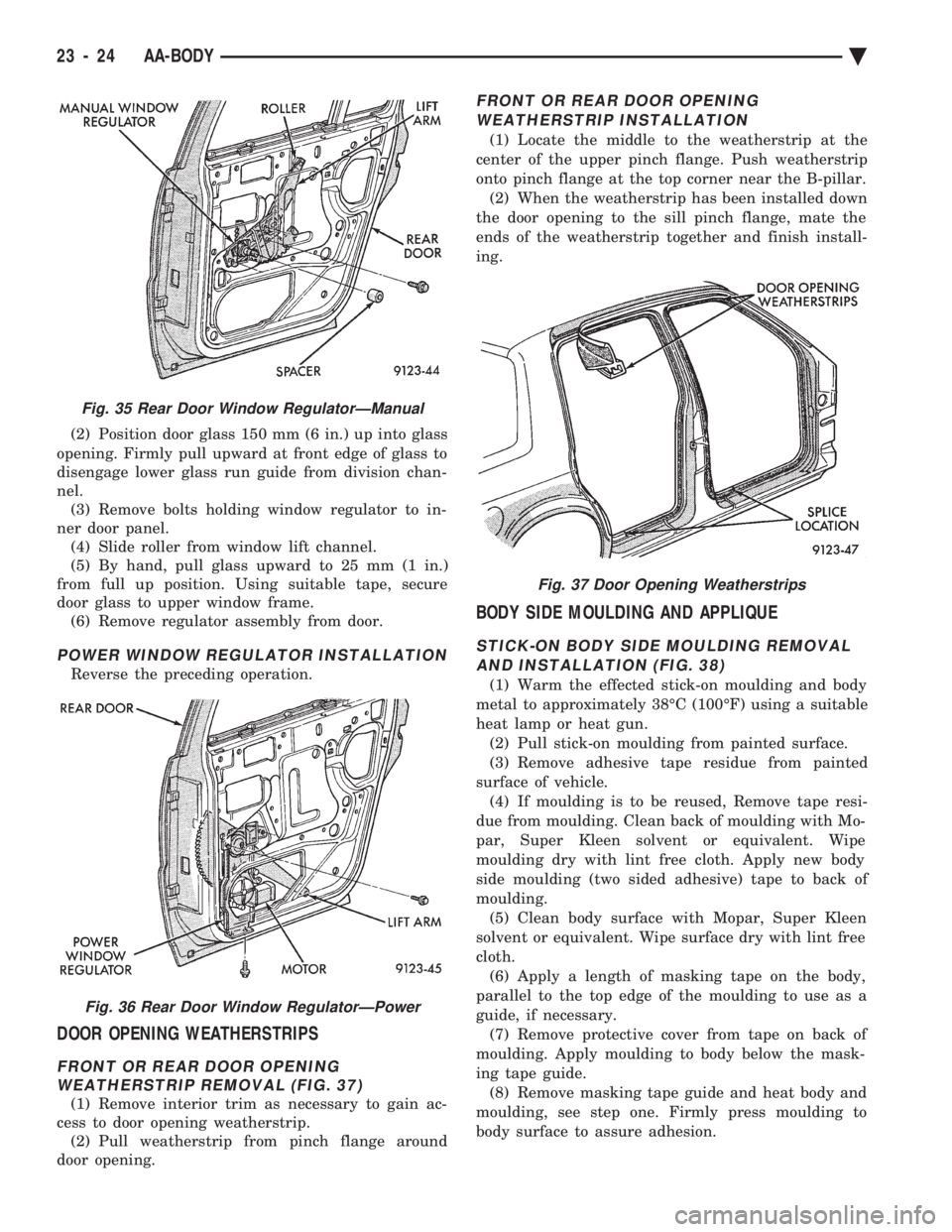
(2) Position door glass 150 mm (6 in.) up into glass
opening. Firmly pull upward at front edge of glass to
disengage lower glass run guide from division chan-
nel. (3) Remove bolts holding window regulator to in-
ner door panel. (4) Slide roller from window lift channel.
(5) By hand, pull glass upward to 25 mm (1 in.)
from full up position. Using suitable tape, secure
door glass to upper window frame. (6) Remove regulator assembly from door.
POWER WINDOW REGULATOR INSTALLATION
Reverse the preceding operation.
DOOR OPENING WEATHERSTRIPS
FRONT OR REAR DOOR OPENINGWEATHERSTRIP REMOVAL (FIG. 37)
(1) Remove interior trim as necessary to gain ac-
cess to door opening weatherstrip. (2) Pull weatherstrip from pinch flange around
door opening.
FRONT OR REAR DOOR OPENING
WEATHERSTRIP INSTALLATION
(1) Locate the middle to the weatherstrip at the
center of the upper pinch flange. Push weatherstrip
onto pinch flange at the top corner near the B-pillar. (2) When the weatherstrip has been installed down
the door opening to the sill pinch flange, mate the
ends of the weatherstrip together and finish install-
ing.
BODY SIDE MOULDING AND APPLIQUE
STICK-ON BODY SIDE MOULDING REMOVAL AND INSTALLATION (FIG. 38)
(1) Warm the effected stick-on moulding and body
metal to approximately 38ÉC (100ÉF) using a suitable
heat lamp or heat gun. (2) Pull stick-on moulding from painted surface.
(3) Remove adhesive tape residue from painted
surface of vehicle. (4) If moulding is to be reused, Remove tape resi-
due from moulding. Clean back of moulding with Mo-
par, Super Kleen solvent or equivalent. Wipe
moulding dry with lint free cloth. Apply new body
side moulding (two sided adhesive) tape to back of
moulding. (5) Clean body surface with Mopar, Super Kleen
solvent or equivalent. Wipe surface dry with lint free
cloth. (6) Apply a length of masking tape on the body,
parallel to the top edge of the moulding to use as a
guide, if necessary. (7) Remove protective cover from tape on back of
moulding. Apply moulding to body below the mask-
ing tape guide. (8) Remove masking tape guide and heat body and
moulding, see step one. Firmly press moulding to
body surface to assure adhesion.
Fig. 35 Rear Door Window RegulatorÐManual
Fig. 36 Rear Door Window RegulatorÐPower
Fig. 37 Door Opening Weatherstrips
23 - 24 AA-BODY Ä