1993 CHEVROLET PLYMOUTH ACCLAIM length
[x] Cancel search: lengthPage 2205 of 2438
REAR SEATS
REAR SEAT CUSHION REMOVAL
(1) Remove bolts holding cushion to floor.
(2) Disconnect center occupant seat belts from
cushion. (3) Remove cushion from vehicle.
REAR SEAT CUSHION INSTALLATION
Reverse the preceding operation.
REAR SEAT BACK REMOVAL
(1) Remove rear seat cushion assembly.
(2) Remove bolts holding seat back to rear floor
kick-up. (3) Lift seat back upward to disengage upper hooks
from shelf support panel. (4) Separate seat back from vehicle.
REAR SEAT BACK INSTALLATION
Reverse the preceding operation.
BODY MOULDINGS
STICK-ON BODY SIDE MOULDING REMOVALAND INSTALLATION
(1) Warm the effected stick-on moulding and body
metal to approximately 38ÉC (100ÉF) using a suitable
heat lamp or heat gun. (2) Pull stick-on moulding from painted surface.
(3) Remove adhesive tape residue from painted
surface of vehicle. (4) If moulding is to be reused, Remove tape resi-
due from moulding. Clean back of moulding with Mo-
par t, Super Kleen solvent or equivalent. Wipe
moulding dry with lint free cloth. Apply new body
side moulding (two sided adhesive) tape to back of
moulding. (5) Clean body surface with Super Kleen solvent or
equivalent. Wipe surface dry with lint free cloth. (6) Apply a length of masking tape on the body,
parallel to the top edge of the moulding to use as a
guide, if necessary. (7) Remove protective cover from tape on back of
moulding. Apply moulding to body below the mask-
ing tape guide. (8) Remove masking tape guide and heat body and
moulding, see step one. Firmly press moulding to
body surface to assure adhesion.
FRONT WHEEL OPENING MOULDING REMOVAL
(1) Remove screws holding wheel opening mould-
ing to front fender. (2) Separate moulding from fender.
FRONT WHEEL OPENING MOULDINGINSTALLATION
(1) Position moulding in wheel opening and start
top center screw of wheel opening moulding. (2) Install screws around wheel opening.
REAR WHEEL OPENING MOULDING REMOVAL
(1) Remove screws holding wheel opening mould-
ing to quarter panel. (2) Separate wheel opening moulding from quarter
panel.
REAR WHEEL OPENING MOULDING INSTALLATION
(1) Position moulding in wheel opening and start
top center screw of wheel opening moulding. (2) Install screws around wheel opening.
VINYL ROOF BONNET
REMOVAL (FIG. 27)
(1) Remove quarter panel trim covers.
(2) Remove head lining.
(3) Remove nuts holding transverse roof moulding
to roof panel and separate moulding from vehicle. (4) Remove nuts holding vinyl top bonnet to roof.
(5) Remove rear deck filler panel.
(6) Remove screws holding rear window opening
lower valance to body. (7) Disengage hook and loop fasteners holding vi-
nyl top bonnet to quarter panel. (8) Pull vinyl top bonnet away from top panel to
separate bonnet from anti-flutter sealer holding bon-
net to roof.
INSTALLATION
(1) Clean anti-flutter sealer from roof surface and
inside of vinyl roof bonnet. (2) Apply a 20 mm (0.75 in.) bead of anti-flutter
sealer across the roof panel at the mid point between
the front of the bonnet and rear of roof. (3) Apply a 20 mm (0.75 in.) by 150 mm (6 in.)
bead of anti-flutter sealer down each roof side panel
at mid point between the door opening and rear of
roof. (4) Place the bonnet into position on the roof panel
and align to proper fit. (5) Reverse the removal operation.
REAR DECK FILLER PANEL
REMOVAL (FIG. 28)
(1) Raise truck lid to full up position.
(2) Remove screws holding rear deck filler panel to
body in the front trunk opening gutter. (3) Close trunk lid, do not latch.
(4) Lift filler panel upward and separate from ve-
hicle.
Ä AC-BODY 23 - 49
Page 2216 of 2438
DOOR OPENING WEATHERSTRIPS
REMOVAL
(1) Remove interior trim as necessary to gain ac-
cess to door opening weatherstrip. (2) Pull weatherstrip from pinch flange around
door opening.
INSTALLATION
(1) Locate the middle to the weatherstrip at the
center of the upper pinch flange. Push weatherstrip
onto pinch flange at the top corner near the B-pillar. (2) When the weatherstrip has been installed down
the door opening to the sill pinch flange, mate the
ends of the weatherstrip together and finish install-
ing.
BODY SIDE MOULDINGS
STICK-ON BODY SIDE MOULDING REMOVAL AND INSTALLATION
(1) Warm the effected stick-on moulding and body
metal to approximately 38ÉC (100ÉF) using a suitable
heat lamp or heat gun. (2) Pull stick-on moulding from painted surface.
(3) Remove adhesive tape residue from painted
surface of vehicle. (4) If moulding is to be reused, Remove tape resi-
due from moulding. Clean back of moulding with Mo-
par, Super Kleen solvent or equivalent. Wipe moulding dry with lint free cloth. Apply new body
side moulding (two sided adhesive) tape to back of
moulding. (5) Clean body surface with Mopar, Super Kleen
solvent or equivalent. Wipe surface dry with lint free
cloth. (6) Apply a length of masking tape on the body,
parallel to the top edge of the moulding to use as a
guide, if necessary. (7) Remove protective cover from tape on back of
moulding. Apply moulding to body below the mask-
ing tape guide. (8) Remove masking tape guide and heat body and
moulding, refer to step one. Firmly press moulding to
body surface to assure adhesion.
BODY SIDE APPLIQUE
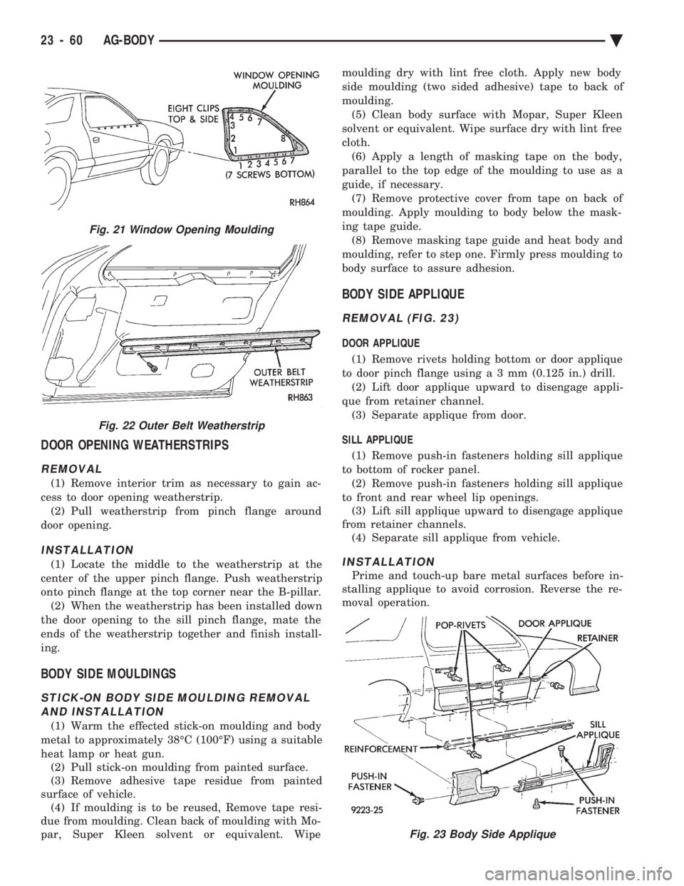
REMOVAL (FIG. 23)
DOOR APPLIQUE
(1) Remove rivets holding bottom or door applique
to door pinch flange usin ga3mm(0.125 in.) drill.
(2) Lift door applique upward to disengage appli-
que from retainer channel. (3) Separate applique from door.
SILL APPLIQUE (1) Remove push-in fasteners holding sill applique
to bottom of rocker panel. (2) Remove push-in fasteners holding sill applique
to front and rear wheel lip openings. (3) Lift sill applique upward to disengage applique
from retainer channels. (4) Separate sill applique from vehicle.
INSTALLATION
Prime and touch-up bare metal surfaces before in-
stalling applique to avoid corrosion. Reverse the re-
moval operation.
Fig. 21 Window Opening Moulding
Fig. 22 Outer Belt Weatherstrip
Fig. 23 Body Side Applique
23 - 60 AG-BODY Ä
Page 2248 of 2438
ADJUSTMENT PROCEDURES
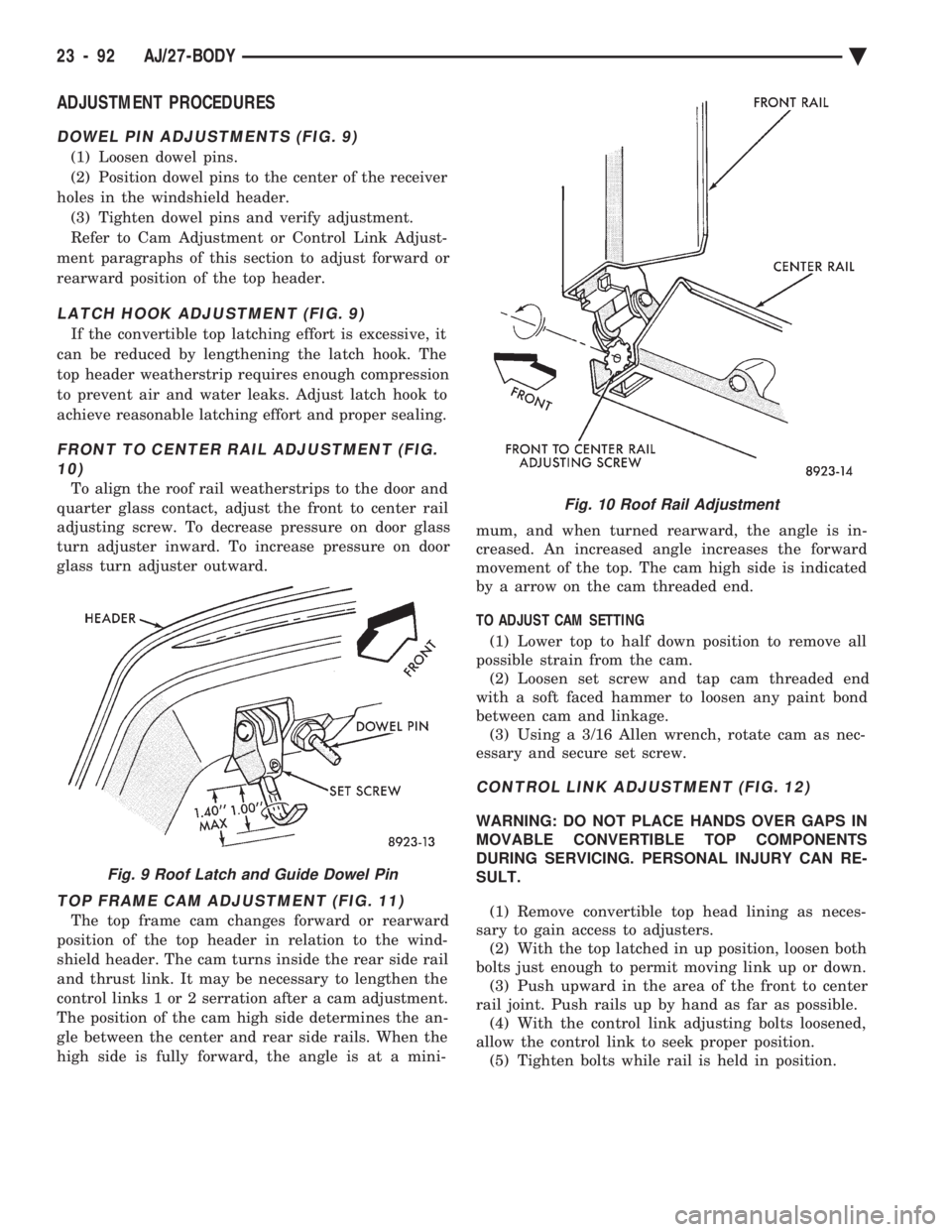
DOWEL PIN ADJUSTMENTS (FIG. 9)
(1) Loosen dowel pins.
(2) Position dowel pins to the center of the receiver
holes in the windshield header. (3) Tighten dowel pins and verify adjustment.
Refer to Cam Adjustment or Control Link Adjust-
ment paragraphs of this section to adjust forward or
rearward position of the top header.
LATCH HOOK ADJUSTMENT (FIG. 9)
If the convertible top latching effort is excessive, it
can be reduced by lengthening the latch hook. The
top header weatherstrip requires enough compression
to prevent air and water leaks. Adjust latch hook to
achieve reasonable latching effort and proper sealing.
FRONT TO CENTER RAIL ADJUSTMENT (FIG. 10)
To align the roof rail weatherstrips to the door and
quarter glass contact, adjust the front to center rail
adjusting screw. To decrease pressure on door glass
turn adjuster inward. To increase pressure on door
glass turn adjuster outward.
TOP FRAME CAM ADJUSTMENT (FIG. 11)
The top frame cam changes forward or rearward
position of the top header in relation to the wind-
shield header. The cam turns inside the rear side rail
and thrust link. It may be necessary to lengthen the
control links 1 or 2 serration after a cam adjustment.
The position of the cam high side determines the an-
gle between the center and rear side rails. When the
high side is fully forward, the angle is at a mini- mum, and when turned rearward, the angle is in-
creased. An increased angle increases the forward
movement of the top. The cam high side is indicated
by a arrow on the cam threaded end.
TO ADJUST CAM SETTING (1) Lower top to half down position to remove all
possible strain from the cam. (2) Loosen set screw and tap cam threaded end
with a soft faced hammer to loosen any paint bond
between cam and linkage. (3) Using a 3/16 Allen wrench, rotate cam as nec-
essary and secure set screw.
CONTROL LINK ADJUSTMENT (FIG. 12)
WARNING: DO NOT PLACE HANDS OVER GAPS IN
MOVABLE CONVERTIBLE TOP COMPONENTS
DURING SERVICING. PERSONAL INJURY CAN RE-
SULT.
(1) Remove convertible top head lining as neces-
sary to gain access to adjusters. (2) With the top latched in up position, loosen both
bolts just enough to permit moving link up or down. (3) Push upward in the area of the front to center
rail joint. Push rails up by hand as far as possible. (4) With the control link adjusting bolts loosened,
allow the control link to seek proper position. (5) Tighten bolts while rail is held in position.
Fig. 9 Roof Latch and Guide Dowel Pin
Fig. 10 Roof Rail Adjustment
23 - 92 AJ/27-BODY Ä
Page 2264 of 2438
(2) When the weatherstrip has been installed down
the door opening to the sill pinch flange, mate the
ends of the weatherstrip together and finish install-
ing.
QUARTER GLASS WINDOW
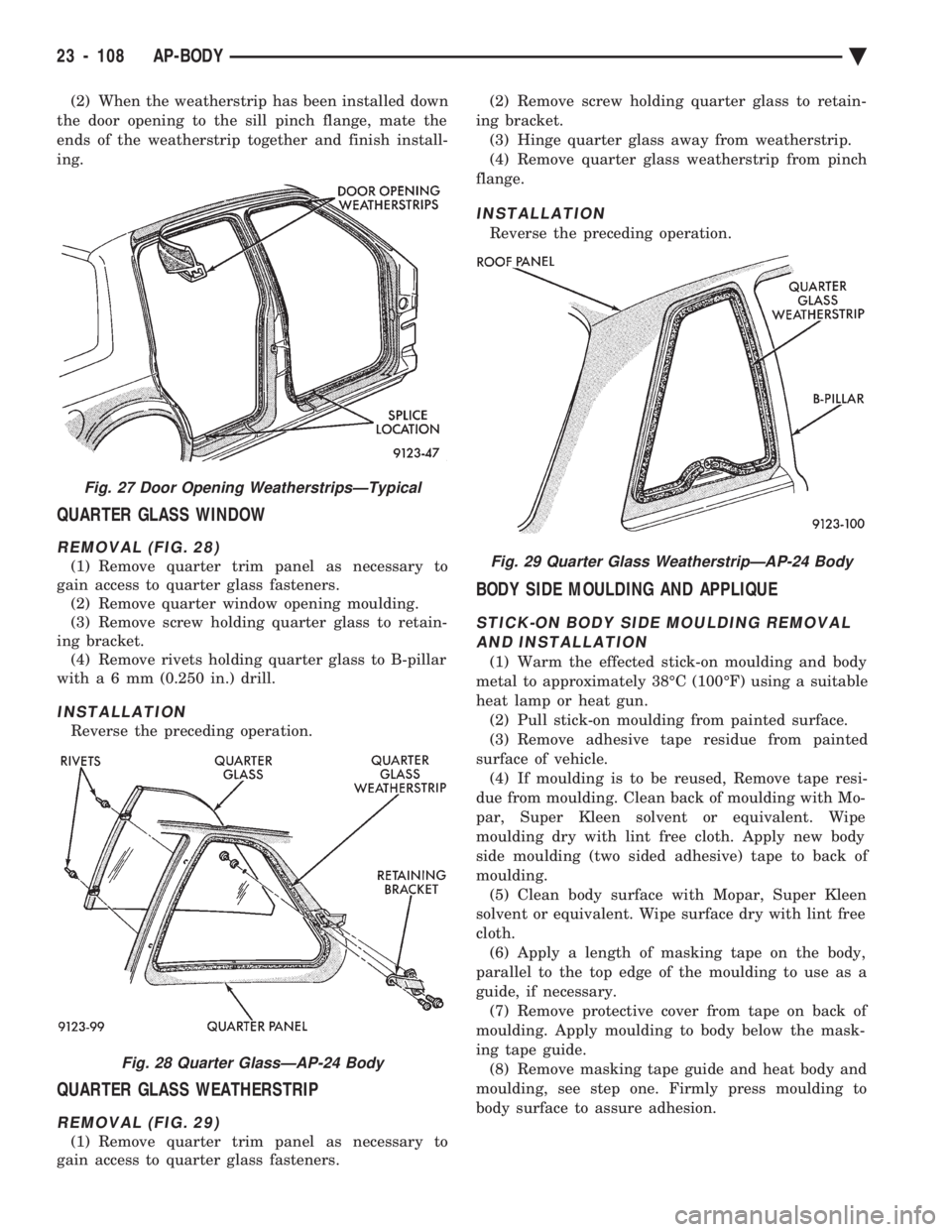
REMOVAL (FIG. 28)
(1) Remove quarter trim panel as necessary to
gain access to quarter glass fasteners. (2) Remove quarter window opening moulding.
(3) Remove screw holding quarter glass to retain-
ing bracket. (4) Remove rivets holding quarter glass to B-pillar
witha6mm (0.250 in.) drill.
INSTALLATION
Reverse the preceding operation.
QUARTER GLASS WEATHERSTRIP
REMOVAL (FIG. 29)
(1) Remove quarter trim panel as necessary to
gain access to quarter glass fasteners. (2) Remove screw holding quarter glass to retain-
ing bracket. (3) Hinge quarter glass away from weatherstrip.
(4) Remove quarter glass weatherstrip from pinch
flange.
INSTALLATION
Reverse the preceding operation.
BODY SIDE MOULDING AND APPLIQUE
STICK-ON BODY SIDE MOULDING REMOVAL AND INSTALLATION
(1) Warm the effected stick-on moulding and body
metal to approximately 38ÉC (100ÉF) using a suitable
heat lamp or heat gun. (2) Pull stick-on moulding from painted surface.
(3) Remove adhesive tape residue from painted
surface of vehicle. (4) If moulding is to be reused, Remove tape resi-
due from moulding. Clean back of moulding with Mo-
par, Super Kleen solvent or equivalent. Wipe
moulding dry with lint free cloth. Apply new body
side moulding (two sided adhesive) tape to back of
moulding. (5) Clean body surface with Mopar, Super Kleen
solvent or equivalent. Wipe surface dry with lint free
cloth. (6) Apply a length of masking tape on the body,
parallel to the top edge of the moulding to use as a
guide, if necessary. (7) Remove protective cover from tape on back of
moulding. Apply moulding to body below the mask-
ing tape guide. (8) Remove masking tape guide and heat body and
moulding, see step one. Firmly press moulding to
body surface to assure adhesion.
Fig. 27 Door Opening WeatherstripsÐTypical
Fig. 28 Quarter GlassÐAP-24 Body
Fig. 29 Quarter Glass WeatherstripÐAP-24 Body
23 - 108 AP-BODY Ä
Page 2302 of 2438
(3) Remove cushion from vehicle.
REAR SEAT CUSHION INSTALLATION
Reverse the preceding operation.
REAR SEAT BACK REMOVAL
(1) Remove rear seat cushion assembly.
(2) Remove bolts holding seat back to rear floor
kick-up. (3) Lift seat back upward to disengage upper hooks
from shelf support panel. (4) Separate seat back from vehicle.
REAR SEAT BACK INSTALLATION
Reverse the preceding operation.
BODY MOULDINGS
STICK-ON BODY SIDE MOULDING REMOVALAND INSTALLATION
(1) Warm the effected stick-on moulding and body
metal to approximately 38ÉC (100ÉF) using a suitable
heat lamp or heat gun. (2) Pull stick-on moulding from painted surface.
(3) Remove adhesive tape residue from painted
surface of vehicle. (4) If moulding is to be reused, Remove tape resi-
due from moulding. Clean back of moulding with Mo-
par, Super Kleen solvent or equivalent. Wipe
moulding dry with lint free cloth. Apply new body
side moulding (two sided adhesive) tape to back of
moulding. (5) Clean body surface with Mopar, Super Kleen
solvent or equivalent. Wipe surface dry with lint free
cloth. (6) Apply a length of masking tape on the body,
parallel to the top edge of the moulding to use as a
guide, if necessary. (7) Remove protective cover from tape on back of
moulding. Apply moulding to body below the mask-
ing tape guide. (8) Remove masking tape guide and heat body and
moulding, see step one. Firmly press moulding to
body surface to assure adhesion.
FRONT WHEEL OPENING MOULDING REMOVAL
(1) Remove screws holding wheel opening mould-
ing to front fender. (2) Separate moulding from fender.
FRONT WHEEL OPENING MOULDINGINSTALLATION
(1) Position moulding in wheel opening and start
top center screw of wheel opening moulding. (2) Install screws around wheel opening.
REAR WHEEL OPENING MOULDING REMOVAL
(1) Remove screws holding wheel opening mould-
ing to quarter panel. (2) Separate wheel opening moulding from quarter
panel.
REAR WHEEL OPENING MOULDING INSTALLATION
(1) Position moulding in wheel opening and start
top center screw of wheel opening moulding. (2) Install screws around wheel opening.
VINYL ROOF BONNET
REMOVAL (FIG. 30)
(1) Remove quarter panel trim covers.
(2) Remove head lining.
(3) Remove nuts holding transverse roof moulding
to roof panel and separate moulding from vehicle. (4) Remove nuts holding vinyl top bonnet to roof.
(5) Remove rear deck filler panel.
(6) Remove screws holding rear window opening
lower valance to body. (7) Disengage clips holding vinyl top bonnet to
quarter panel. (8) Pull vinyl top bonnet away from top panel to
separate bonnet from anti-flutter sealer holding bon-
net to roof.
INSTALLATION
(1) Clean anti-flutter sealer from roof surface and
inside of vinyl roof bonnet. (2) Apply a 20 mm (0.75 in.) bead of anti-flutter
sealer across the roof panel at the mid point between
the front of the bonnet and rear of roof. (3) Apply a 20 mm (0.75 in.) by 150 mm (6 in.)
bead of anti-flutter sealer down each roof side panel
at mid point between the door opening and rear of
roof. (4) Place the bonnet into position on the roof panel
and align to proper fit. (5) Reverse the removal operation.
REAR DECK FILLER PANEL
REMOVAL (FIG. 31)
(1) Raise truck lid to full up position.
(2) Remove screws holding rear deck filler panel to
body in the front trunk opening gutter. (3) Close trunk lid, do not latch.
(4) Lift filler panel upward and separate from ve-
hicle.
INSTALLATION
Reverse the preceding operation.
23 - 146 AY-BODY Ä