1993 CHEVROLET PLYMOUTH ACCLAIM length
[x] Cancel search: lengthPage 439 of 2438
(3) Plug the demagnetizing tool into a standard
110/115 volt AC outlet, keeping the demagnetizing
tool at least 12 inches away from the compass area
when plugging it in. (4) Slowly approach the console mounting screw
with the plastic coated tip of the tool for at least 2
seconds. (5) With the demagnetizing tool still energized,
slowly back it away from the screw until the tip is at
least 12 inches from the screw head. (6) After you have pulled at least 12 inches from
the last screw, remove the demagnetizer tool from in-
side of the vehicle and disconnect it from the electri-
cal outlet. (7) Place an 8 1/2 X 11 inch piece of paper length-
wise on the roof of vehicle directly above compass.
The purpose of the paper is to protect the roof panel
from scratches and define the area to be demagne-
tized. (8) Plug in the demagnetizing tool, keeping it at
least 2 feet away from the compass unit. (9) Slowly approach the center of the roof panel at
the windshield with the demagnetizing tool plugged
in. (10) Contact the roof panel with the tip of the tool
and using slow sweeping motions of 1/2 inch between sweeps. Move the tool approximately 4 inches either
side of the centerline and at least 11 inches back
from the windshield. (11) With the demagnetizing tool still energized,
slowly back away from the roof panel until the tip is
at least 2 feet from the roof before unplugging the
tool. (12) Recalibrate compass.
COMPASS DIAGNOSTICS
To place the unit into the diagnostics mode, turn
the vehicle ignition off. Depress the Comp/Temp but-
ton while turning on the ignition/run switch. The
display will then show DO. There are 3 tests that
can be performed when in the diagnostics mode.
Press the U.S./Metric button to choose test desired.
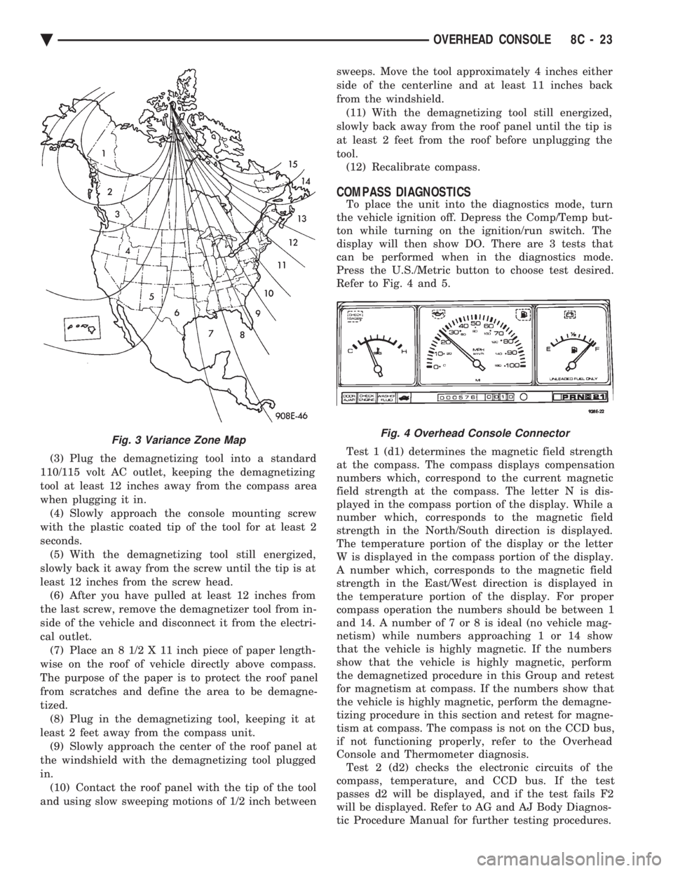
Refer to Fig. 4 and 5.
Test 1 (d1) determines the magnetic field strength
at the compass. The compass displays compensation
numbers which, correspond to the current magnetic
field strength at the compass. The letter N is dis-
played in the compass portion of the display. While a
number which, corresponds to the magnetic field
strength in the North/South direction is displayed.
The temperature portion of the display or the letter
W is displayed in the compass portion of the display.
A number which, corresponds to the magnetic field
strength in the East/West direction is displayed in
the temperature portion of the display. For proper
compass operation the numbers should be between 1
and 14. A number of 7 or 8 is ideal (no vehicle mag-
netism) while numbers approaching 1 or 14 show
that the vehicle is highly magnetic. If the numbers
show that the vehicle is highly magnetic, perform
the demagnetized procedure in this Group and retest
for magnetism at compass. If the numbers show that
the vehicle is highly magnetic, perform the demagne-
tizing procedure in this section and retest for magne-
tism at compass. The compass is not on the CCD bus,
if not functioning properly, refer to the Overhead
Console and Thermometer diagnosis. Test 2 (d2) checks the electronic circuits of the
compass, temperature, and CCD bus. If the test
passes d2 will be displayed, and if the test fails F2
will be displayed. Refer to AG and AJ Body Diagnos-
tic Procedure Manual for further testing procedures.
Fig. 3 Variance Zone MapFig. 4 Overhead Console Connector
Ä OVERHEAD CONSOLE 8C - 23
Page 445 of 2438
When testing secondary cables for punctures and
cracks with an oscilloscope follow the equipment
manufacturers instructions. If an oscilloscope is not available, secondary cables
can be tested as follows:
CAUTION: Do not leave any one spark plug cable
disconnected any longer than necessary during test-
ing. Excessive heat could damage the catalytic con-
verter. Total test time must not exceed ten minutes.
(a) With the engine not running, connect one end
of a test probe to a good ground. Use a probe made of
insulated wire with insulated alligator clips on each
end. (b) With engine running, move test probe along
entire length of all cables (approximately 0 to 1/8
inch gap). If punctures or cracks are present there
will be a noticeable spark jump from the faulty area
to the probe. Check the coil cable the same way.
Replace cracked, leaking or faulty cables.
When replacing cables, install the new high
tension cable and nipple assembly over cap or
coil tower. When entering the terminal into the
tower, push lightly, then pinch the large diam-
eter of nipple to release air trapped between the
nipple and tower. Continue pushing on the cable
and nipple until cables are properly seated in the
cap towers. A snap should be heard as terminal
goes into place. Use the same procedure to install cable in coil tower.
Wipe the spark plug insulator clean before reinstalling
cable and cover. Use the following procedure when removing the high
tension cable from the spark plug. First, remove the
cable from the retaining bracket. Then grasp the ter-
minal as close as possible to the spark plug. Rotate the
cover and pull the cable straight back. Pulling on the
cable itself will damage the conductor and termi-
nal connection. Do not use pliers and do not pull
the cable at an angle. Doing so will damage the
insulation, cable terminal or the spark plug in-
sulator. Wipe spark plug insulator clean before
reinstalling cable and cover. Resistance type cable is identified by the words
Electronic Suppression printed on the cable jacket.
Use an ohmmeter to check resistance type cable for
open circuits, loose terminals or high resistance as
follows: (a) Remove cable from spark plug.
(b) Lift distributor cap from distributor with
cables intact. Do not remove cables from cap. The
cables must be removed from the spark plugs. (c) Connect the ohmmeter between spark plug end
terminal and the corresponding electrode inside the
cap, make sure ohmmeter probes are in good contact.
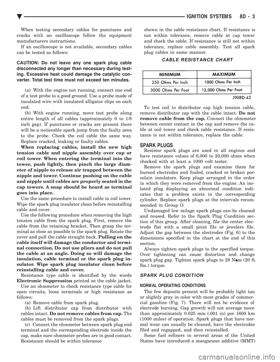
Resistance should be within tolerance shown in the cable resistance chart. If resistance is
not within tolerance, remove cable at cap tower
and check the cable. If resistance is still not within
tolerance, replace cable assembly. Test all spark
plug cables in same manner.
To test coil to distributor cap high tension cable,
remove distributor cap with the cable intact. Do not
remove cable from the cap. Connect the ohmmeter
between center contact in the cap and remove the ca-
ble at coil tower and check cable resistance. If resis-
tance is not within tolerance, replace the cable.
SPARK PLUGS
Resistor spark plugs are used in all engines and
have resistance values of 6,000 to 20,000 ohms when
checked with at least a 1000 volt tester. Remove the spark plugs and examine them for
burned electrodes and fouled, cracked or broken por-
celain insulators. Keep plugs arranged in the order
in which they were removed from the engine. An iso-
lated plug displaying an abnormal condition indi-
cates that a problem exists in the corresponding
cylinder. Replace spark plugs at the intervals recom-
mended in Group O. Undamaged low milage spark plugs can be cleaned
and reused. Refer to the Spark Plug Condition sec-
tion of this group. After cleaning, file the center elec-
trode flat with a small point file or jewelers file.
Adjust the gap between the electrodes (Fig. 6) to the
dimensions specified in the chart at the end of this
section. Always tighten spark plugs to the specified torque.
Over tightening can cause distortion and change
spark plug gap. Tighten spark plugs to 28 N Im (20 ft.
lbs.) torque.
SPARK PLUG CONDITION
NORMAL OPERATING CONDITIONS
The few deposits present will be probably light tan
or slightly gray in color with most grades of commer-
cial gasoline (Fig. 7). There will not be evidence of
electrode burning. Gap growth will not average more
than approximately 0.025 mm (.001 in) per 1600 km
(1000 miles) of operation. Spark plugs that have nor-
mal wear can usually be cleaned, have the electrodes
filed and regapped, and then reinstalled. Some fuel refiners in several areas of the United
States have introduced a manganese additive (MMT)
CABLE RESISTANCE CHART
Ä IGNITION SYSTEMS 8D - 3
Page 447 of 2438
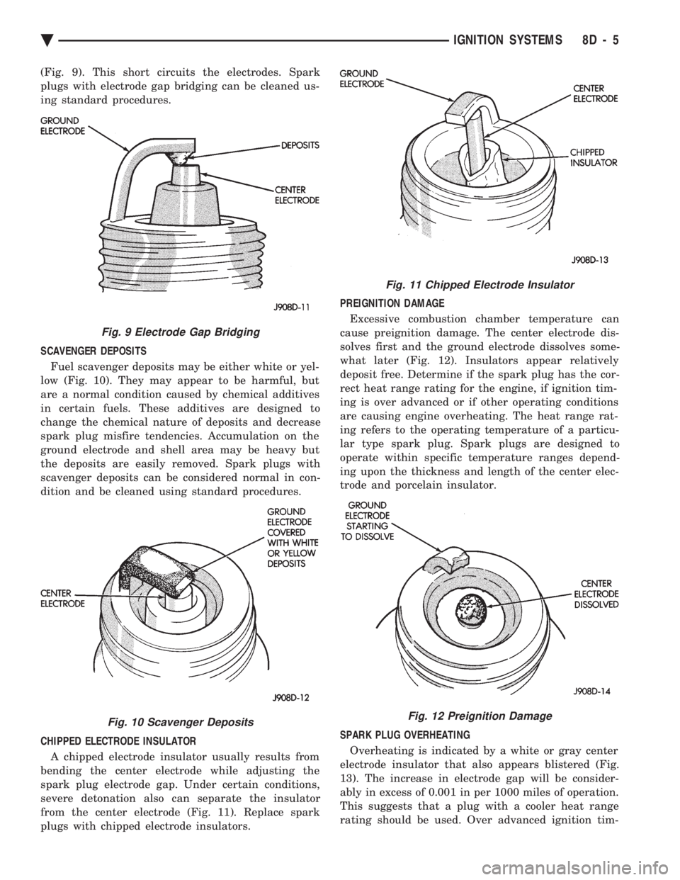
(Fig. 9). This short circuits the electrodes. Spark
plugs with electrode gap bridging can be cleaned us-
ing standard procedures.
SCAVENGER DEPOSITS Fuel scavenger deposits may be either white or yel-
low (Fig. 10). They may appear to be harmful, but
are a normal condition caused by chemical additives
in certain fuels. These additives are designed to
change the chemical nature of deposits and decrease
spark plug misfire tendencies. Accumulation on the
ground electrode and shell area may be heavy but
the deposits are easily removed. Spark plugs with
scavenger deposits can be considered normal in con-
dition and be cleaned using standard procedures.
CHIPPED ELECTRODE INSULATOR A chipped electrode insulator usually results from
bending the center electrode while adjusting the
spark plug electrode gap. Under certain conditions,
severe detonation also can separate the insulator
from the center electrode (Fig. 11). Replace spark
plugs with chipped electrode insulators. PREIGNITION DAMAGE
Excessive combustion chamber temperature can
cause preignition damage. The center electrode dis-
solves first and the ground electrode dissolves some-
what later (Fig. 12). Insulators appear relatively
deposit free. Determine if the spark plug has the cor-
rect heat range rating for the engine, if ignition tim-
ing is over advanced or if other operating conditions
are causing engine overheating. The heat range rat-
ing refers to the operating temperature of a particu-
lar type spark plug. Spark plugs are designed to
operate within specific temperature ranges depend-
ing upon the thickness and length of the center elec-
trode and porcelain insulator.
SPARK PLUG OVERHEATING Overheating is indicated by a white or gray center
electrode insulator that also appears blistered (Fig.
13). The increase in electrode gap will be consider-
ably in excess of 0.001 in per 1000 miles of operation.
This suggests that a plug with a cooler heat range
rating should be used. Over advanced ignition tim-
Fig. 9 Electrode Gap Bridging
Fig. 10 Scavenger Deposits
Fig. 11 Chipped Electrode Insulator
Fig. 12 Preignition Damage
Ä IGNITION SYSTEMS 8D - 5
Page 470 of 2438

SCAVENGER DEPOSITS Fuel scavenger deposits may be either white or yel-
low (Fig. 12). They may appear to be harmful, but
are a normal condition caused by chemical additives
in certain fuels. These additives are designed to
change the chemical nature of deposits and decrease
spark plug misfire tendencies. Accumulation on the
ground electrode and shell area may be heavy but
the deposits are easily removed. Spark plugs with
scavenger deposits can be considered normal in con-
dition and be cleaned using standard procedures.
CHIPPED ELECTRODE INSULATOR A chipped electrode insulator usually results from
bending the center electrode while adjusting the
spark plug electrode gap. Under certain conditions,
severe detonation also can separate the insulator
from the center electrode (Fig. 13). Spark plugs with
chipped electrode insulators must be replaced.
PREIGNITION DAMAGE
Excessive combustion chamber temperature can
cause preignition damage. First, the center electrode
dissolves and the ground electrode dissolves some- what later (Fig. 14). Insulators appear relatively de-
posit free. Determine if the spark plug has the
correct heat range rating for the engine, if ignition
timing is over advanced or if other operating condi-
tions are causing engine overheating. The heat range
rating refers to the operating temperature of a par-
ticular type spark plug. Spark plugs are designed to
operate within specific temperature ranges depend-
ing upon the thickness and length of the center elec-
trode and porcelain insulator.
SPARK PLUG OVERHEATING
Overheating is indicated by a white or gray center
electrode insulator that also appears blistered (Fig.
15). The increase in electrode gap will be consider-
ably in excess of 0.001 in per 1000 miles of operation.
This suggests that a plug with a cooler heat range
rating should be used. Over advanced ignition tim-
ing, detonation and cooling system malfunctions also
can cause spark plug overheating.
CAMSHAFT POSITION SENSOR
The camshaft position sensor provides fuel injection
synchronization and cylinder identification informa-
Fig. 12 Scavenger Deposits
Fig. 13 Chipped Electrode Insulator
Fig. 14 Preignition Damage
Fig. 15 Spark Plug Overheating
8D - 28 IGNITION SYSTEMS Ä
Page 483 of 2438

(2) With engine running, move test probe along
entire length of all cables (approximately 0 to 1/8
inch gap). If punctures or cracks are present there
will be a noticeable spark jump from the faulty area
to the probe. Cracked, leaking or faulty cables should
be replaced. Use the following procedure when removing the
high tension cable from the spark plug. First, remove
the cable from the retaining bracket. Then grasp the
terminal as close as possible to the spark plug. Ro-
tate the cover (boot) slightly and pull straight back.
Do not use pliers and do not pull the cable at an
angle. Doing so will damage the insulation, cable
terminal or the spark plug insulator. Wipe spark
plug insulator clean before reinstalling cable
and cover. Resistance cables are identified by the words Elec-
tronic Suppression .
Use an ohmmeter to check cables for opens, loose
terminals or high resistance. (a) Remove cable from spark plug.
(b) Remove cable from the coil tower.
(c) Connect the ohmmeter between spark plug
end terminal and the coil end terminal. Resistance
should be within tolerance shown in the cable re-
sistance chart. If resistance is not within tolerance,
replace cable assembly. Test all spark plug cables
in same manner.
SPARK PLUG SERVICE
When replacing the spark plug cables, route the ca-
bles correctly and secure them in the appropriate re-
tainers. Incorrectly routed cables can cause the radio
to reproduce ignition noise. It can also cause cross ig-
nition of the spark plugs or short circuit the cables to
ground.
SPARK PLUG REMOVAL
Always remove cables by grasping at boot, rotating
the boot 1/2 turn, and pulling straight back in a
steady motion. (1) Prior to removing the spark plug spray com-
pressed air around the spark plug hole and the area
around the spark plug. (2) Remove the spark plug using a quality socket
with a rubber or foam insert. (3) Inspect the spark plug condition. Refer to
Spark Plug Condition in this section.
SPARK PLUG GAP ADJUSTMENT
Check the spark plug gap with a gap gauge. If the
gap is not correct, adjust it by bending the ground
electrode (Fig. 6).
SPARK PLUG INSTALLATION
(1) To avoid cross threading, start the spark plug
into the cylinder head by hand. (2) Tighten spark plugs to 28 N Im (20 ft. lbs.)
torque. (3) Install spark plug cables over spark plugs.
IDLE RPM TEST
WARNING: BE SURE TO APPLY PARKING BRAKE
AND/OR BLOCK WHEELS BEFORE PERFORMING
ANY ENGINE RUNNING TESTS.
Engine idle set rpmshould be tested and recorded
as it is when the vehicle is first brought into shop
for testing. This will assist in diagnosing complaints
of engine stalling, creeping and hard shifting on ve-
hicles equipped with automatic transaxle. Refer to the
Throttle Body Minimum Airflow procedures in Group
14.
IGNITION TIMING PROCEDURE
Ignition timing cannot be changed or set on Turbo
III, 3.3L or 3.8L engines. For diagnostic information,
refer to the DRBII scan tool and the appropriate
Powertrain Diagnostics Procedures manual.
CABLE RESISTANCE CHART
Fig. 6 Setting Spark Plug GapÐTypical
Ä IGNITION SYSTEMS 8D - 41
Page 547 of 2438
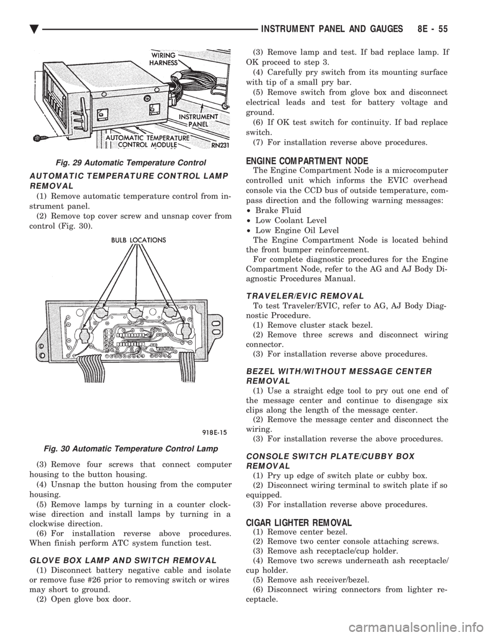
AUTOMATIC TEMPERATURE CONTROL LAMP REMOVAL
(1) Remove automatic temperature control from in-
strument panel. (2) Remove top cover screw and unsnap cover from
control (Fig. 30).
(3) Remove four screws that connect computer
housing to the button housing. (4) Unsnap the button housing from the computer
housing. (5) Remove lamps by turning in a counter clock-
wise direction and install lamps by turning in a
clockwise direction. (6) For installation reverse above procedures.
When finish perform ATC system function test.
GLOVE BOX LAMP AND SWITCH REMOVAL
(1) Disconnect battery negative cable and isolate
or remove fuse #26 prior to removing switch or wires
may short to ground. (2) Open glove box door. (3) Remove lamp and test. If bad replace lamp. If
OK proceed to step 3. (4) Carefully pry switch from its mounting surface
with tip of a small pry bar. (5) Remove switch from glove box and disconnect
electrical leads and test for battery voltage and
ground. (6) If OK test switch for continuity. If bad replace
switch. (7) For installation reverse above procedures.
ENGINE COMPARTMENT NODE
The Engine Compartment Node is a microcomputer
controlled unit which informs the EVIC overhead
console via the CCD bus of outside temperature, com-
pass direction and the following warning messages:
² Brake Fluid
² Low Coolant Level
² Low Engine Oil Level
The Engine Compartment Node is located behind
the front bumper reinforcement. For complete diagnostic procedures for the Engine
Compartment Node, refer to the AG and AJ Body Di-
agnostic Procedures Manual.
TRAVELER/EVIC REMOVAL
To test Traveler/EVIC, refer to AG, AJ Body Diag-
nostic Procedure. (1) Remove cluster stack bezel.
(2) Remove three screws and disconnect wiring
connector. (3) For installation reverse above procedures.
BEZEL WITH/WITHOUT MESSAGE CENTERREMOVAL
(1) Use a straight edge tool to pry out one end of
the message center and continue to disengage six
clips along the length of the message center. (2) Remove the message center and disconnect the
wiring. (3) For installation reverse the above procedures.
CONSOLE SWITCH PLATE/CUBBY BOXREMOVAL
(1) Pry up edge of switch plate or cubby box.
(2) Disconnect wiring terminal to switch plate if so
equipped. (3) For installation reverse above procedures.
CIGAR LIGHTER REMOVAL
(1) Remove center bezel.
(2) Remove two center console attaching screws.
(3) Remove ash receptacle/cup holder.
(4) Remove two screws underneath ash receptacle/
cup holder. (5) Remove ash receiver/bezel.
(6) Disconnect wiring connectors from lighter re-
ceptacle.
Fig. 29 Automatic Temperature Control
Fig. 30 Automatic Temperature Control Lamp
Ä INSTRUMENT PANEL AND GAUGES 8E - 55
Page 587 of 2438

INSTALLATION
(1) Install antenna body and cable from under-
neath fender (Fig. 12). (2) Install gasket, adapter, and cap nut. Tighten
cap nut to 14 N Im (125 in. lbs.) with Antenna Nut
Wrench C-4816. (3) Install antenna mast into antenna body until
sleeve bottoms on antenna body (Fig. 11). (4) Route cable to radio if necessary.
BENCH TEST FOR ANTENNA MALFUNCTION
It is also possible to check short or open circuits
with an ohmmeter or continuity light once the an-
tenna has been removed from the vehicle. (1) Continuity should be present between the tip of
the mast and radio end pin (Fig. 13 and 14).
(2) No continuity should be observed or a very high
resistance of several megohms between the ground
shell of the connector and radio end pin.
(3) Continuity should be observed between the ground
shell of the connector and the mounting hardware.
Wiggle cable over its entire length to reveal inter-
mittent short or open circuits during step 1, 2 and 3.
POWER ANTENNA
OPERATION
The power operated radio antenna (Fig. 15) is a
telescoping type antenna, extended and retracted by a
reversible electric motor. The Automatic Power Antenna is controlled by a
combination of an external relay and limit switches
built into the antenna motor housing. The antenna is
actuated when radio is switched ON and the ignition
switch in ON or ACCESSORY position. The antenna
mast should extend. When the ignition switch or radio
is turned OFF the antenna mast should fully retract
and declutch.
Many antenna problems may be avoided by frequent
cleaning of the antenna mast telescoping sections. Clean
the antenna mast sections with a clean soft cloth.
Before an antenna is removed, the antenna perfor-
mance should be tested to decide if it is a reception
problem or an operational problem. Whenever an operational malfunction occurs, first
verify that the radio antenna wire harness is properly
connected. Check all connectors before starting normal
diagnosis and repair procedures. Refer to Power An-
tenna Electrical Diagnosis Chart (Fig. 16).
Fig. 12 Antenna Mounting
Fig. 11 Removing or Tightening Antenna Cap Nut
Fig. 13 Antenna Bench Test Points
Fig. 14 Antenna Bench Test PointsÐTwo Part
Ä AUDIO SYSTEM 8F - 21
Page 755 of 2438
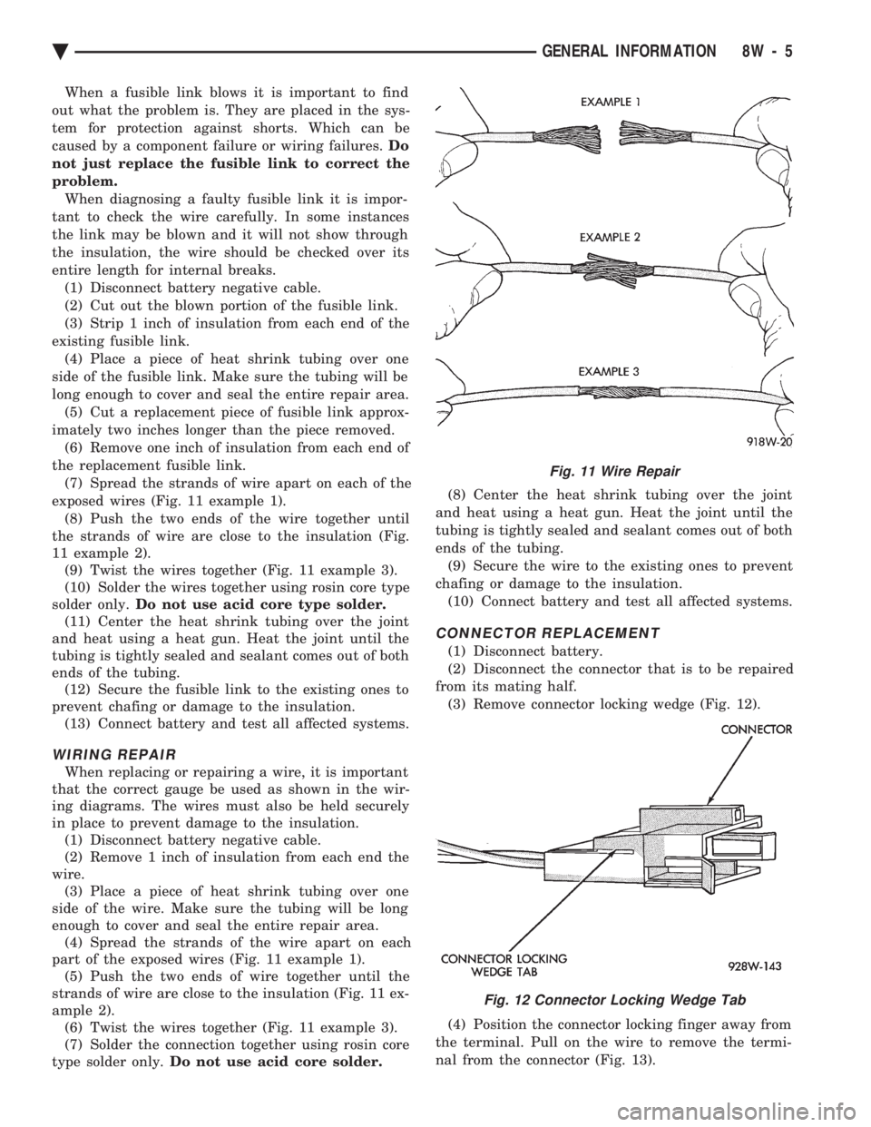
When a fusible link blows it is important to find
out what the problem is. They are placed in the sys-
tem for protection against shorts. Which can be
caused by a component failure or wiring failures. Do
not just replace the fusible link to correct the
problem. When diagnosing a faulty fusible link it is impor-
tant to check the wire carefully. In some instances
the link may be blown and it will not show through
the insulation, the wire should be checked over its
entire length for internal breaks. (1) Disconnect battery negative cable.
(2) Cut out the blown portion of the fusible link.
(3) Strip 1 inch of insulation from each end of the
existing fusible link. (4) Place a piece of heat shrink tubing over one
side of the fusible link. Make sure the tubing will be
long enough to cover and seal the entire repair area. (5) Cut a replacement piece of fusible link approx-
imately two inches longer than the piece removed. (6) Remove one inch of insulation from each end of
the replacement fusible link. (7) Spread the strands of wire apart on each of the
exposed wires (Fig. 11 example 1). (8) Push the two ends of the wire together until
the strands of wire are close to the insulation (Fig.
11 example 2). (9) Twist the wires together (Fig. 11 example 3).
(10) Solder the wires together using rosin core type
solder only. Do not use acid core type solder.
(11) Center the heat shrink tubing over the joint
and heat using a heat gun. Heat the joint until the
tubing is tightly sealed and sealant comes out of both
ends of the tubing. (12) Secure the fusible link to the existing ones to
prevent chafing or damage to the insulation. (13) Connect battery and test all affected systems.
WIRING REPAIR
When replacing or repairing a wire, it is important
that the correct gauge be used as shown in the wir-
ing diagrams. The wires must also be held securely
in place to prevent damage to the insulation. (1) Disconnect battery negative cable.
(2) Remove 1 inch of insulation from each end the
wire. (3) Place a piece of heat shrink tubing over one
side of the wire. Make sure the tubing will be long
enough to cover and seal the entire repair area. (4) Spread the strands of the wire apart on each
part of the exposed wires (Fig. 11 example 1). (5) Push the two ends of wire together until the
strands of wire are close to the insulation (Fig. 11 ex-
ample 2). (6) Twist the wires together (Fig. 11 example 3).
(7) Solder the connection together using rosin core
type solder only. Do not use acid core solder. (8) Center the heat shrink tubing over the joint
and heat using a heat gun. Heat the joint until the
tubing is tightly sealed and sealant comes out of both
ends of the tubing. (9) Secure the wire to the existing ones to prevent
chafing or damage to the insulation. (10) Connect battery and test all affected systems.
CONNECTOR REPLACEMENT
(1) Disconnect battery.
(2) Disconnect the connector that is to be repaired
from its mating half. (3) Remove connector locking wedge (Fig. 12).
(4) Position the connector locking finger away from
the terminal. Pull on the wire to remove the termi-
nal from the connector (Fig. 13).
Fig. 11 Wire Repair
Fig. 12 Connector Locking Wedge Tab
Ä GENERAL INFORMATION 8W - 5