1993 CHEVROLET PLYMOUTH ACCLAIM length
[x] Cancel search: lengthPage 161 of 2438

BRAKE HOSE AND TUBING
INSPECTION OF BRAKE HOSE AND TUBING
Flexible rubber hose is used at both front brakes and
at the rear axle. Inspection of brake hoses should be
performed whenever the brake system is serviced and
every 7,500 miles or 12 months, whichever comes first
(every engine oil change). Inspect hydraulic brake
hoses for severe surface cracking, scuffing, or worn
spots. Should the fabric casing of the rubber hose be
exposed due to cracks or abrasions in the rubber hose
cover, the hose should be replaced immediately. Even-
tual deterioration of the hose can take place with
possible burst failure. Faulty installation can cause
twisting and wheel, tire or chassis interference. The steel brake tubing should be inspected periodi-
cally for evidence of physical damage or contact with
moving or hot components.
INSTALLATION OF BRAKE HOSE
Always use factory recommended brake hose to en-
sure quality, correct length and superior fatigue life.
Care should be taken to make sure that the tube and
hose mating surfaces are clean and free from nicks and
burrs. Front right and left side hoses are not
interchangeable. Connections should be correct and properly made.
Use new copper seal washers on all connections using
Banjo Bolts and tighten all fittings to their specified
torques. The flexible front hydraulic brake hose should al-
ways be installed on the vehicle by first attaching the
Banjo connector to the caliper assembly. Then bolt the
intermediate hose bracket to the strut assembly allow-
ing the bracket to position the hose to prevent twisting.
Attach the hose to the body bracket and steel brake
tubing. Tighten all fittings to specified torque. The
body bracket and hose end are keyed so that they will
only fit one way. Install rear brake hoses first to the trailing arm
tubes and then to the floor pan tubes. Minimize hose
twisting. Vehicles equipped with rear disc brakes have
brake hoses attached to the caliper on each side. The
brake hose should be first attached by the Banjo bolt to
the caliper and then secured to the hose bracket with
the retaining clip. The attach the steel brake tubing to
the hose fitting.
REPAIR AND INSTALLATION OF BRAKE TUB- ING
Only double wall 4.75mm (3/16 in.) steel tubing
should be used for replacement. Care should be taken
when replacing brake tubing, to be sure the proper
bending and flaring tools and procedures are used, to
avoid kinking. Do not route the tubes against sharp edges, moving components or into hot areas. All
tubes should be properly attached with recommended
retaining clips.
TYPES OF TUBING FLARES
Two different tubing flares (Fig. 13) are used on 93
M.Y. vehicles. On some ABS brake systems the tub-
ing connections made to the hydraulic assembly use
an ISO flare. All other ABS brake system compo-
nent, tubing connections are made using a double in-
verted flare. On non-ABS brake systems all
component tubing connections use only the double in-
verted flare. No ISO flares are used.
CAUTION: ALWAYS USE THE PROPER FLARING
TOOL AND PROCEDURE, FOR THE TYPE OF
BRAKE SYSTEM THAT IS BEING SERVICED TO IN-
SURE THE INTEGRITY OF THE HYDRAULIC SYS-
TEM.
TO REPAIR OR FLARE TUBING
Using Tubing Cutter, Special Tool C-3478-A or
equivalent, cut off damaged seat or tubing (Fig. 14).
Ream out any burrs or rough edges showing on in-
side of tubing (Fig. 15). This will make the ends of
tubing square (Fig. 15) and ensure better seating of
flared end tubing. PLACE TUBE NUT ON TUB-
ING BEFORE FLARING THE TUBING.
DOUBLE INVERTED TUBING FLARES.
To make a double inverted tubing flare (Fig. 13 &
16). Open handles of Flaring Tool, Special Tool
C-4047 or equivalent. Then rotate jaws of tool until
the mating jaws of tubing size are centered between
vertical posts on tool. Slowly close handles with tub-
Fig. 13 Identifying Hydraulic Brake Tubing Flares
Ä BRAKES 5 - 11
Page 193 of 2438

Position dust boot in counterbore of the caliper piston
bore. Using a hammer and Installer Piston Caliper Boot,
Special Tool C-4689 and Handle, Special Tool C-4171,
drive boot into counterbore of the caliper (Fig. 3).
Use the following steps, to install the Guide Pin
Sleeve Bushings into the caliper assembly. (1) Fold the bushing in half lengthwise at the solid
middle section of the bushing (Fig. 4).
(2) Using your fingers insert the folded bushing into
the caliper assembly (Fig. 5). Do not use a sharp
object to perform this step do to possible damage
to the bushing. (3) Unfold the bushing using your fingers or a
wooden dowel until the bushing is fully seated into the caliper assembly. Flanges should be seated
evenly on both sides of the bushing hole in the cali-
per assembly (Fig. 6).
Install the Guide Pin Sleeve into the guide bushing
using the following procedure. (1) Install the sleeve into one end of the bushing
until the seal area of the bushing is past the seal
groove in the sleeve (Fig. 7). (2) Holding the convoluted end of the bushing with
one hand. Push the sleeve through the bushing (Fig.
Fig. 5 Installing Caliper Guide Pin Sleeve Bushings
Fig. 6 Bushing Correctly Installed In Caliper
Fig. 3 Installing Dust Boot in Caliper Counterbore
Fig. 4 Folded Caliper Guide Pin Bushing
Ä BRAKES 5 - 43
Page 201 of 2438
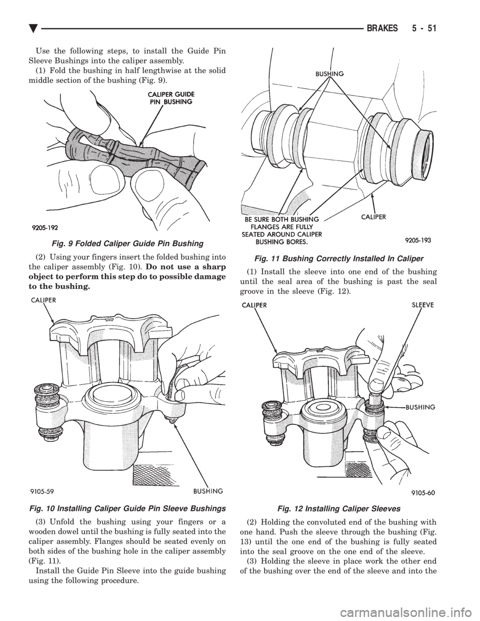
Use the following steps, to install the Guide Pin
Sleeve Bushings into the caliper assembly. (1) Fold the bushing in half lengthwise at the solid
middle section of the bushing (Fig. 9).
(2) Using your fingers insert the folded bushing into
the caliper assembly (Fig. 10). Do not use a sharp
object to perform this step do to possible damage
to the bushing.
(3) Unfold the bushing using your fingers or a
wooden dowel until the bushing is fully seated into the
caliper assembly. Flanges should be seated evenly on
both sides of the bushing hole in the caliper assembly
(Fig. 11). Install the Guide Pin Sleeve into the guide bushing
using the following procedure. (1) Install the sleeve into one end of the bushing
until the seal area of the bushing is past the seal
groove in the sleeve (Fig. 12).
(2) Holding the convoluted end of the bushing with
one hand. Push the sleeve through the bushing (Fig.
13) until the one end of the bushing is fully seated
into the seal groove on the one end of the sleeve. (3) Holding the sleeve in place work the other end
of the bushing over the end of the sleeve and into the
Fig. 11 Bushing Correctly Installed In Caliper
Fig. 12 Installing Caliper Sleeves
Fig. 9 Folded Caliper Guide Pin Bushing
Fig. 10 Installing Caliper Guide Pin Sleeve Bushings
Ä BRAKES 5 - 51
Page 213 of 2438
PARKING BRAKE HAND LEVER ASSEMBLY
REMOVAL AND INSTALLATION
REMOVAL (AG AND AJ BODY)
Remove ash receiver or courtesy light from rear of
console. Remove carpet from sides of console. Remove
parking brake trim cover from passenger side of con-
sole (pulls off). Load and lockout parking brake self adjuster (Fig.
6). Disconnect rear cables from equalizer bracket. Remove the 3 hold down nuts and remove hand le-
ver assembly through opening created by removing
console trim cover. Passenger seat might have to be
removed. Also, if metal tab at bottom of console pre-
vents removal of hand brake assembly, bend tab out
of the way. (Bend the tab back to original position af-
terR&Rof hand brake).
INSTALLATION (AG AND AJ BODY)
Install hand lever assembly through side opening
in console and bolt into place. Connect rear parking brake cables to equalizer.
Adjust parking brakes.
Install console trim cover, carpet, passenger seat
and rear ash receiver or courtesy light.
REMOVAL AND INSTALLATION PARKING BRAKE
SHOES
ALL WITH REAR DISK BRAKES
(1) Remove rear disc brake caliper assembly from
adapter and braking disc (See Disc Brake Shoe Re-
moval). (2) Remove rear braking disc from rear hub (See
Removing Braking Disk). (3) Remove grease cap.
(4) Remove cotter pin, lock nut, hub bearing re-
taining nut, and washer. (5) Remove hub and bearings.(See Wheel Bearing
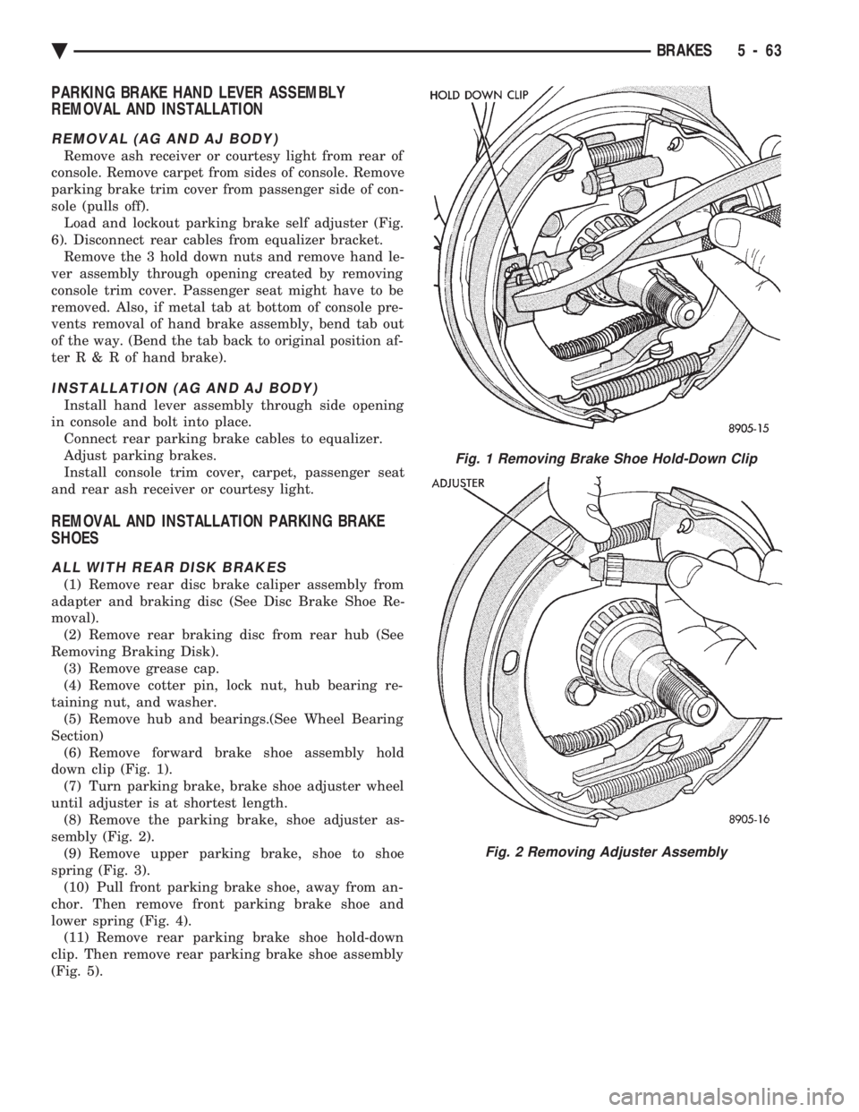
Section) (6) Remove forward brake shoe assembly hold
down clip (Fig. 1). (7) Turn parking brake, brake shoe adjuster wheel
until adjuster is at shortest length. (8) Remove the parking brake, shoe adjuster as-
sembly (Fig. 2). (9) Remove upper parking brake, shoe to shoe
spring (Fig. 3). (10) Pull front parking brake shoe, away from an-
chor. Then remove front parking brake shoe and
lower spring (Fig. 4). (11) Remove rear parking brake shoe hold-down
clip. Then remove rear parking brake shoe assembly
(Fig. 5).
Fig. 1 Removing Brake Shoe Hold-Down Clip
Fig. 2 Removing Adjuster Assembly
Ä BRAKES 5 - 63
Page 344 of 2438

TURBOCHARGER COOLANT ROUTING
Engines equipped with a Turbocharger maintain a
continuous engine coolant flow through the Turbo-
charger bearing housing water jacket. Hose and tube
assemblies provide a closed loop coolant flow from
the cylinder block water jacket to the turbocharger
housing and back to the cylinder head waterbox (Fig.
2). Excluding heated intake manifold hose routing
(hose is routed from waterbox directly to heater), all
other system functions are essentially the same as
shown for standard engines. During any reassembly procedures all pipe fittings
in water jacket, bearing housing and waterbox re-
quire cleaning and application of thread sealant for
entire length of threads. Tighten all fittings to
torque specified in (Fig 2).
WATER PIPESÐ3.0L
The 3.0L engines use metal piping beyond the
lower radiator hose to route coolant to the suction
side of water pump, located in the V of the cylinder
banks. These pipes are also provided with inlet nipples for
thermostat bypass and heater return coolant hos-
es,and brackets for rigid engine attachment. The
pipes employ O-rings for sealing at their interconnec-
tion and to the water pump (Fig. 4).
Fig. 2 Turbocharger-Tube Hose AssembliesÐTurbo III Engine
Fig. 3 Cooling System OperationÐ3.0L Engine
7 - 2 COOLING SYSTEM Ä
Page 420 of 2438
VARIANCE SETTING PROCEDURE
There are two methods for setting variance while
in variance set mode. If the CAL symbol is on proce-
dure 2 must be used.
PROCEDURE 1
(1) Turn ignition switch to the on position.
(2) Press and hold the Comp/Temp button till the
display is turned OFF. (3) While continuing to hold Comp/Temp button
depress and hold US/Metric button until the VAR
symbol lights in approximately 5 seconds. (4) Release buttons.
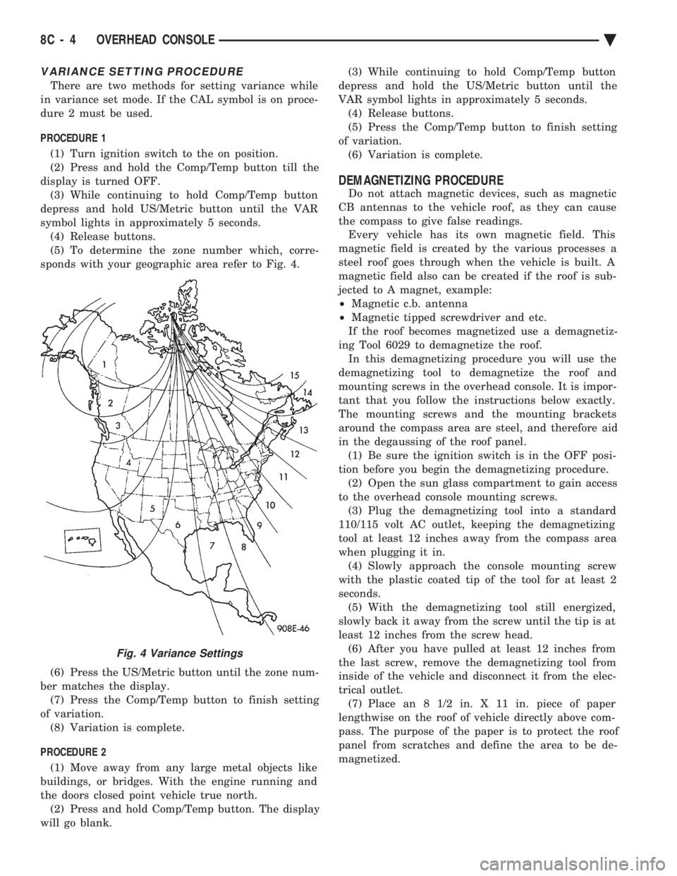
(5) To determine the zone number which, corre-
sponds with your geographic area refer to Fig. 4.
(6) Press the US/Metric button until the zone num-
ber matches the display. (7) Press the Comp/Temp button to finish setting
of variation. (8) Variation is complete.
PROCEDURE 2 (1) Move away from any large metal objects like
buildings, or bridges. With the engine running and
the doors closed point vehicle true north. (2) Press and hold Comp/Temp button. The display
will go blank. (3) While continuing to hold Comp/Temp button
depress and hold the US/Metric button until the
VAR symbol lights in approximately 5 seconds. (4) Release buttons.
(5) Press the Comp/Temp button to finish setting
of variation. (6) Variation is complete.
DEMAGNETIZING PROCEDURE
Do not attach magnetic devices, such as magnetic
CB antennas to the vehicle roof, as they can cause
the compass to give false readings. Every vehicle has its own magnetic field. This
magnetic field is created by the various processes a
steel roof goes through when the vehicle is built. A
magnetic field also can be created if the roof is sub-
jected to A magnet, example:
² Magnetic c.b. antenna
² Magnetic tipped screwdriver and etc.
If the roof becomes magnetized use a demagnetiz-
ing Tool 6029 to demagnetize the roof. In this demagnetizing procedure you will use the
demagnetizing tool to demagnetize the roof and
mounting screws in the overhead console. It is impor-
tant that you follow the instructions below exactly.
The mounting screws and the mounting brackets
around the compass area are steel, and therefore aid
in the degaussing of the roof panel. (1) Be sure the ignition switch is in the OFF posi-
tion before you begin the demagnetizing procedure. (2) Open the sun glass compartment to gain access
to the overhead console mounting screws. (3) Plug the demagnetizing tool into a standard
110/115 volt AC outlet, keeping the demagnetizing
tool at least 12 inches away from the compass area
when plugging it in. (4) Slowly approach the console mounting screw
with the plastic coated tip of the tool for at least 2
seconds. (5) With the demagnetizing tool still energized,
slowly back it away from the screw until the tip is at
least 12 inches from the screw head. (6) After you have pulled at least 12 inches from
the last screw, remove the demagnetizing tool from
inside of the vehicle and disconnect it from the elec-
trical outlet. (7) Place an 8 1/2 in. X 11 in. piece of paper
lengthwise on the roof of vehicle directly above com-
pass. The purpose of the paper is to protect the roof
panel from scratches and define the area to be de-
magnetized.
Fig. 4 Variance Settings
8C - 4 OVERHEAD CONSOLE Ä
Page 433 of 2438
(4) Drive the vehicle 1 to 3 complete circles. The
CAL light will then go off, showing the compass is
calibrated. If the compass portion of the display:
² It does not display.
² Readings are not accurate after calibration.
² The vehicle may have too much magnetism for the
compass to be accurate.
² The compass circuitry is not working properly.
² Refer to Variance Procedure, Demagnetizing Pro-
cedure and/or Compass Diagnostics.
VARIANCE PROCEDURE
Variance is the difference between magnetic North
and geographic North. In some areas the difference
between magnetic and geographic North is great
enough to cause the compass to give false readings. If
this occurs, the variance must be set. To set the variance, depress and hold down both
the Comp/Temp button and the U.S./Metric button.
The display will go off and after 5 seconds the VAR
light will come on. Release both buttons. Using the
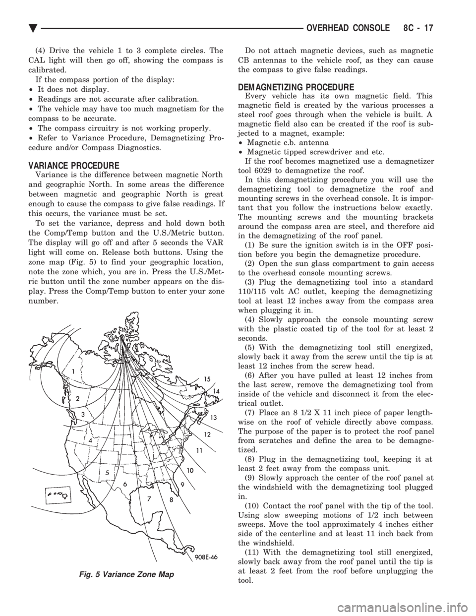
zone map (Fig. 5) to find your geographic location,
note the zone which, you are in. Press the U.S./Met-
ric button until the zone number appears on the dis-
play. Press the Comp/Temp button to enter your zone
number. Do not attach magnetic devices, such as magnetic
CB antennas to the vehicle roof, as they can cause
the compass to give false readings.
DEMAGNETIZING PROCEDURE
Every vehicle has its own magnetic field. This
magnetic field is created by the various processes a
steel roof goes through when the vehicle is built. A
magnetic field also can be created if the roof is sub-
jected to a magnet, example:
² Magnetic c.b. antenna
² Magnetic tipped screwdriver and etc.
If the roof becomes magnetized use a demagnetizer
tool 6029 to demagnetize the roof. In this demagnetizing procedure you will use the
demagnetizing tool to demagnetize the roof and
mounting screws in the overhead console. It is impor-
tant that you follow the instructions below exactly.
The mounting screws and the mounting brackets
around the compass area are steel, and therefore aid
in the demagnetizing of the roof panel. (1) Be sure the ignition switch is in the OFF posi-
tion before you begin the demagnetize procedure. (2) Open the sun glass compartment to gain access
to the overhead console mounting screws. (3) Plug the demagnetizing tool into a standard
110/115 volt AC outlet, keeping the demagnetizing
tool at least 12 inches away from the compass area
when plugging it in. (4) Slowly approach the console mounting screw
with the plastic coated tip of the tool for at least 2
seconds. (5) With the demagnetizing tool still energized,
slowly back it away from the screw until the tip is at
least 12 inches from the screw head. (6) After you have pulled at least 12 inches from
the last screw, remove the demagnetizing tool from
inside of the vehicle and disconnect it from the elec-
trical outlet. (7) Place an 8 1/2 X 11 inch piece of paper length-
wise on the roof of vehicle directly above compass.
The purpose of the paper is to protect the roof panel
from scratches and define the area to be demagne-
tized. (8) Plug in the demagnetizing tool, keeping it at
least 2 feet away from the compass unit. (9) Slowly approach the center of the roof panel at
the windshield with the demagnetizing tool plugged
in. (10) Contact the roof panel with the tip of the tool.
Using slow sweeping motions of 1/2 inch between
sweeps. Move the tool approximately 4 inches either
side of the centerline and at least 11 inch back from
the windshield. (11) With the demagnetizing tool still energized,
slowly back away from the roof panel until the tip is
at least 2 feet from the roof before unplugging the
tool.
Fig. 5 Variance Zone Map
Ä OVERHEAD CONSOLE 8C - 17
Page 436 of 2438
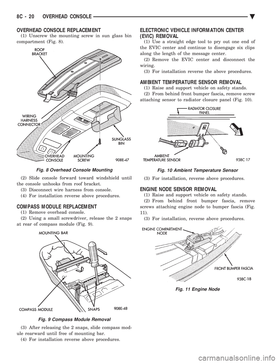
OVERHEAD CONSOLE REPLACEMENT
(1) Unscrew the mounting screw in sun glass bin
compartment (Fig. 8).
(2) Slide console forward toward windshield until
the console unhooks from roof bracket. (3) Disconnect wire harness from console.
(4) For installation reverse above procedures.
COMPASS MODULE REPLACEMENT
(1) Remove overhead console.
(2) Using a small screwdriver, release the 2 snaps
at rear of compass module (Fig. 9).
(3) After releasing the 2 snaps, slide compass mod-
ule rearward until free of mounting bar. (4) For installation reverse above procedures.
ELECTRONIC VEHICLE INFORMATION CENTER
(EVIC) REMOVAL
(1) Use a straight edge tool to pry out one end of
the EVIC center and continue to disengage six clips
along the length of the message center. (2) Remove the EVIC center and disconnect the
wiring. (3) For installation reverse the above procedures.
AMBIENT TEMPERATURE SENSOR REMOVAL
(1) Raise and support vehicle on safety stands.
(2) From behind front bumper fascia, remove screw
attaching sensor to radiator closure panel (Fig. 10).
(3) For installation, reverse above procedures.
ENGINE NODE SENSOR REMOVAL
(1) Raise and support vehicle on safety stands.
(2) From behind front bumper fascia, remove
screws attaching engine node to bumper fascia (Fig.
11). (3) For installation, reverse above procedures.
Fig. 8 Overhead Console Mounting
Fig. 9 Compass Module Removal
Fig. 10 Ambient Temperature Sensor
Fig. 11 Engine Node
8C - 20 OVERHEAD CONSOLE Ä