1993 CHEVROLET PLYMOUTH ACCLAIM radiator
[x] Cancel search: radiatorPage 2352 of 2438
WARNING: AVOID RADIATOR/CONDENSER FAN
BLADES WHEN WORKING IN THE RADIATOR
AREA. FAN IS CONTROLLED BY TEMPERATURE
AND CAN START ANY TIME IGNITION IS ON. PER-
SONAL INJURY CAN RESULT.
(1) Disconnect fan control switch wire connector.
(2) Using a suitable jumper wire, jump across ter-
minals in wire connector. (3) Connect a suitable continuity tester across fan
control switch terminals. (4) Start engine and set idle at 1300 rpm. The ra-
diator fan should run constantly. (5) Set the A/C controls to A/C and high blower.
(6) If the high pressure gauge reads below 1102
kPa (160 psi) there should be no continuity across
the switch terminals.
CAUTION: Do not allow engine to overheat when ra-
diator air flow is blocked.
(7) Block radiator air flow with a suitable cover to
increase the high side pressure to at least 1585 kPa
(230 psi). Electrical continuity should be detected
across the fan control switch terminals. (8) Remove cover from front of vehicle to allow
high side pressure to decrease. When pressure drops
below 1102 kPa (160 psi), continuity should cease. If fan control switch is defective, replace it.
REMOVAL AND INSTALLATION
CAUTION: Refrigerant removal is not necessary
when removing the Condenser Fan Control Switch.
However, a small amount of refrigerant will vent
from the switch port. Review the refrigerant han-
dling section of Safety Precautions and Warnings in
the General Information section of this Group.
(1) Disconnect wire connector from condenser fan
control switch. (2) Loosen and quickly rotate the switch counter-
clockwise and separate from the high pressure line
switch port. To install, reverse the preceding operation.
DIFFERENTIAL PRESSURE CUT-OUT SWITCH
DIAGNOSIS
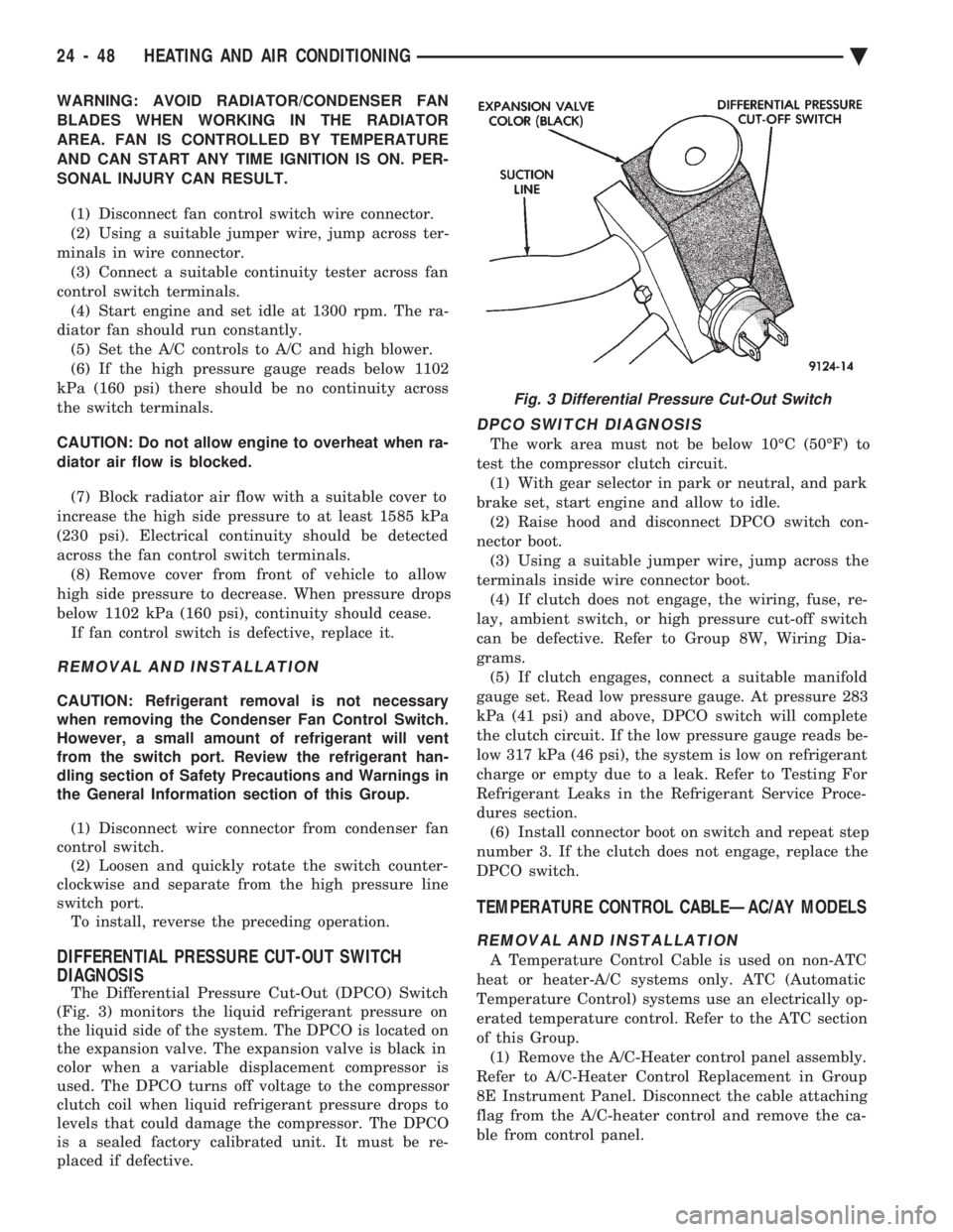
The Differential Pressure Cut-Out (DPCO) Switch
(Fig. 3) monitors the liquid refrigerant pressure on
the liquid side of the system. The DPCO is located on
the expansion valve. The expansion valve is black in
color when a variable displacement compressor is
used. The DPCO turns off voltage to the compressor
clutch coil when liquid refrigerant pressure drops to
levels that could damage the compressor. The DPCO
is a sealed factory calibrated unit. It must be re-
placed if defective.
DPCO SWITCH DIAGNOSIS
The work area must not be below 10ÉC (50ÉF) to
test the compressor clutch circuit. (1) With gear selector in park or neutral, and park
brake set, start engine and allow to idle. (2) Raise hood and disconnect DPCO switch con-
nector boot. (3) Using a suitable jumper wire, jump across the
terminals inside wire connector boot. (4) If clutch does not engage, the wiring, fuse, re-
lay, ambient switch, or high pressure cut-off switch
can be defective. Refer to Group 8W, Wiring Dia-
grams. (5) If clutch engages, connect a suitable manifold
gauge set. Read low pressure gauge. At pressure 283
kPa (41 psi) and above, DPCO switch will complete
the clutch circuit. If the low pressure gauge reads be-
low 317 kPa (46 psi), the system is low on refrigerant
charge or empty due to a leak. Refer to Testing For
Refrigerant Leaks in the Refrigerant Service Proce-
dures section. (6) Install connector boot on switch and repeat step
number 3. If the clutch does not engage, replace the
DPCO switch.
TEMPERATURE CONTROL CABLEÐAC/AY MODELS
REMOVAL AND INSTALLATION
A Temperature Control Cable is used on non-ATC
heat or heater-A/C systems only. ATC (Automatic
Temperature Control) systems use an electrically op-
erated temperature control. Refer to the ATC section
of this Group. (1) Remove the A/C-Heater control panel assembly.
Refer to A/C-Heater Control Replacement in Group
8E Instrument Panel. Disconnect the cable attaching
flag from the A/C-heater control and remove the ca-
ble from control panel.
Fig. 3 Differential Pressure Cut-Out Switch
24 - 48 HEATING AND AIR CONDITIONING Ä
Page 2361 of 2438
INSTALLATION
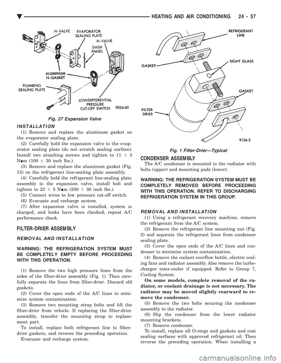
(1) Remove and replace the aluminum gasket on
the evaporator sealing plate. (2) Carefully hold the expansion valve to the evap-
orator sealing plate (do not scratch sealing surface).
Install two attaching screws and tighten to 11 63
N Im (100 630 inch lbs.).
(3) Remove and replace the aluminum gasket (Fig.
15) on the refrigerant line-sealing plate assembly. (4) Carefully hold the refrigerant line-sealing plate
assembly to the expansion valve, install bolt and
tighten to 23 63N Im (200 630 inch lbs.).
(5) Connect wires to low pressure cut-off switch.
(6) Evacuate and recharge system.
(7) After expansion valve is installed, system is
charged, and leaks have been checked, repeat A/C
performance check.
FILTER-DRIER ASSEMBLY
REMOVAL AND INSTALLATION
WARNING: THE REFRIGERATION SYSTEM MUST
BE COMPLETELY EMPTY BEFORE PROCEEDING
WITH THIS OPERATION.
(1) Remove the two high pressure lines from the
sides of the filter-drier assembly (Fig. 1). Then care-
fully separate the lines from filter-drier. Discard old
gaskets. (2) Cover the open ends of the A/C lines to mini-
mize system contamination. (3) Remove two mounting strap bolts and lift the
filter-drier from vehicle. If replacing the filter-drier
assembly, transfer the mounting strap to replace-
ment part. To install, replace both refrigerant line to filter-
drier gaskets, and reverse the preceding operation. Evacuate and recharge system.
CONDENSER ASSEMBLY
The A/C condenser is mounted to the radiator with
bolts (upper) and mounting pads (lower).
WARNING: THE REFRIGERATION SYSTEM MUST BE
COMPLETELY REMOVED BEFORE PROCEEDING
WITH THIS OPERATION. REFER TO DISCHARGING
REFRIGERATION SYSTEM IN THIS GROUP.
REMOVAL AND INSTALLATION
(1) Using a refrigerant recovery machine, remove
the refrigerant from the A/C system. (2) Remove the refrigerant line mounting nut (Fig.
2) and separate the refrigerant lines from condenser
sealing plate. (3) Cover the open ends of the A/C lines and con-
denser to minimize system contamination. (4) Remove the coolant overflow bottle, electric cool-
ing fans and radiator assembly. Also remove the turbo-
charger inter-cooler if equipped. Refer to Group 7,
Cooling System. On some models, complete removal of the ra-
diator, or coolant drainage is not necessary. The
radiator may be moved slightly rearward to re-
move the condenser. (5) Remove the two bolts securing the condenser
assembly to the radiator. (6) Slip the condenser from the lower radiator
mounting brackets. (7) Remove condenser.
To install, replace all O-rings and gaskets and coat
sealing surfaces with approved refrigerant oil. Then
reverse the preceding operation. When installing a
Fig. 27 Expansion Valve
Fig. 1 Filter-DrierÐTypical
Ä HEATING AND AIR CONDITIONING 24 - 57
Page 2365 of 2438
HEATER-A/C UNIT ASSEMBLYÐREMOVAL AND
INSTALLATION
AP, AC, AY BODY PROCEDURE
WARNING: IF EQUIPPED WITH A/C, THE REFRIG-
ERATION SYSTEM MUST BE COMPLETELY EMPTY
BEFORE PROCEEDING WITH THIS OPERATION.
(1) Disconnect battery NEGATIVE cable.
(2) Drain radiator and disconnect heater hoses at
unit. Tape heater tubes to keep from leaking during
removal. Refer to Group 7, Cooling System. (3) Remove A/C condensate drain and disconnect
vacuum lines. (4) Inside passenger compartment, perform as fol-
lows, according to body designation. (a) AC-body, remove right upper and lower un-
der-panel silencers. (b) AP & AC-bodies, remove steering column
cover. (c) AC-body, remove left under-panel silencer.
(5) Position front seat or right front seat full rear. (a) AP-body, remove right A-pillar trim.
(b) Remove right cowl side trim.
(6) Remove glove box. (a) AC-body, remove right instrument panel re-
inforcement.
(7) AP-body only: (a) Remove right instrument panel lower mount-
ing screw. (b) Remove center bezel.
(c) Remove lower center module cover.
(d) Remove floor console.
(e) Remove instrument panel support brace (from
steering column opening to right cowl side at bot-
tom of instrument panel). (f) Remove instrument panel to support bracket
(below glove box opening). (g) Remove ash receiver.
(h) Remove radio.
(i) Remove panel top cover.
(j) Remove three right side panel to fence (below
windshield) attaching screws.
(8) AC-body, remove ash receiver.
(9) AP body, pull right lower side of instrument
panel rearward. (10) Remove center distribution and defroster
adapter ducts. (11) AP and AC-bodies, disconnect relay module.
(12) AP-body, remove instrument panel to unit
bracket. (13) AP-body, remove lower air distribution duct.
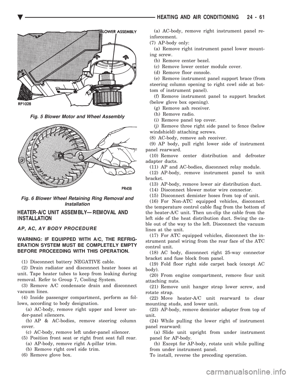
(14) Disconnect blower motor wire connector.
(15) Disconnect demister hoses from top of unit.
(16) For Non-ATC equipped vehicles, disconnect
the temperature control cable flag from the bottom of
the heater-A/C unit. Then un-clip the cable from the
left side of the heat distribution duct. Swing the ca-
ble out of the way to the left. Disconnect the vacuum
lines at the unit. (17) For ATC equipped vehicles, disconnect the in-
strument panel wiring from the rear face of the ATC
control unit. (18) AC body, disconnect right 25-way connector
bracket and fuse block from panel. (19) Fold floor right side carpet back (except AC
body). (20) From engine compartment, remove four unit
attaching nuts. (21) Remove unit hanger strap lower screw, and
rotate strap. (22) Move heater-A/C unit rearward to clear
mounting studs, and lower unit. (23) AP-body, remove demister adapter from top of
unit. (24) While pulling the lower right of instrument
panel rearward: (a) Slide unit upright from under instrument
panel for AP-body. (b) Except for AP-body, rotate unit while pulling
from under instrument panel.
To install, reverse the preceding operation.
Fig. 5 Blower Motor and Wheel Assembly
Fig. 6 Blower Wheel Retaining Ring Removal and Installation
Ä HEATING AND AIR CONDITIONING 24 - 61
Page 2376 of 2438
NONÐCOMPUTER AIDED DIAGNOSTIC TESTS
Determine whether the operator complaint is due
to a system failure or improper operation of the ATC
system. The system will to go into a maximum heat
or cooling mode if the operator changes the tempera-
ture setting four or more degrees. Check the following:
² Coolant level
² Refrigerant charge
² Drive belt tension
² Radiator air flow
² Radiator fan operation
² Air suction of In-car Temperature Sensor/Aspirator
To check air suction of the Aspirator, place a small
piece of tissue paper over the Aspirator opening on
the instrument panel. This opening is located to the
right of the steering column. The tissue paper should
cling to the opening if system is functioning properly. Bring the engine to normal operating temperature
and proceed with Computer Aided Diagnostic Proce-
dures. Always test the entire system after each re-
pair has been performed.
COMPUTER AIDED DIAGNOSTIC TESTS
The ATC control has a computer capable of trou-
bleshooting the entire ATC system in approximately
60 seconds. The engine must be running and at nor-
mal operating temperature during the test to provide
hot coolant for the heater. During the ATC Diagnostic Test, the computer will
calibrate the Mode and Blend Door actuators.
CAUTION: Do not remove the actuators from the
heater-A/C unit assembly with power applied. Re-
moval should only be done with the Ignition OFF.
The actuators have no mechanical stops to limit the
travel. If the actuator rotates and is not connected
to the unit assembly, it will become un-calibrated.
The Diagnostic Test is capable of checking all elec-
trical signals between the ATC Control Module, ac-
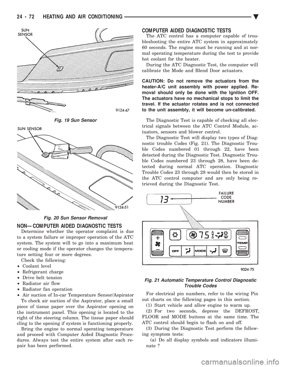
tuators, sensors and blower control. The Diagnostic Test will display two types of Diag-
nostic trouble Codes (Fig. 21). The Diagnostic Trou-
ble Codes numbered 01 through 22, have been
detected during the Diagnostic Test. Diagnostic Trou-
ble Codes numbered 23 through 28, have been de-
tected during normal ATC operation. Diagnostic
Trouble Codes 23 through 28 would then be stored in
the ATC control computer and are only being re-
trieved during the Diagnostic Test.
For electrical pin numbers, refer to the wiring Pin
out charts on the following pages in this section. (1) Start vehicle and allow engine to warm up.
(2) For two seconds, depress the DEFROST,
FLOOR and MODE buttons at the same time. The
ATC control should begin to flash on and off. (3) During the Diagnostic Test perform the follow-
ing symptom tests: (a) Do all display symbols and indicators illumi-
nate ?
Fig. 19 Sun Sensor
Fig. 20 Sun Sensor Removal
Fig. 21 Automatic Temperature Control Diagnostic Trouble Codes
24 - 72 HEATING AND AIR CONDITIONING Ä
Page 2417 of 2438
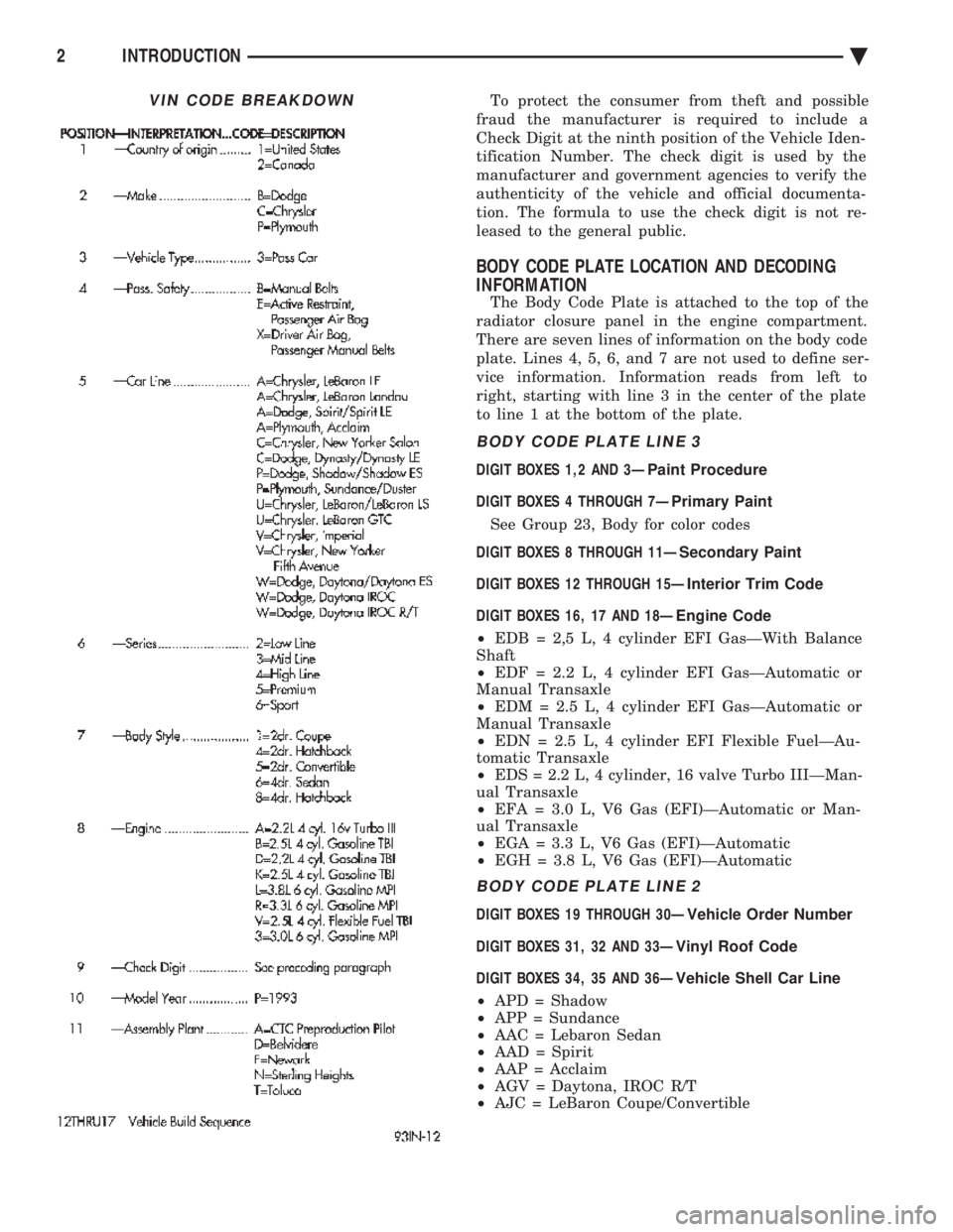
To protect the consumer from theft and possible
fraud the manufacturer is required to include a
Check Digit at the ninth position of the Vehicle Iden-
tification Number. The check digit is used by the
manufacturer and government agencies to verify the
authenticity of the vehicle and official documenta-
tion. The formula to use the check digit is not re-
leased to the general public.
BODY CODE PLATE LOCATION AND DECODING
INFORMATION
The Body Code Plate is attached to the top of the
radiator closure panel in the engine compartment.
There are seven lines of information on the body code
plate. Lines 4, 5, 6, and 7 are not used to define ser-
vice information. Information reads from left to
right, starting with line 3 in the center of the plate
to line 1 at the bottom of the plate.
BODY CODE PLATE LINE 3
DIGIT BOXES 1,2 AND 3Ð Paint Procedure
DIGIT BOXES 4 THROUGH 7Ð Primary Paint
See Group 23, Body for color codes
DIGIT BOXES 8 THROUGH 11Ð Secondary Paint
DIGIT BOXES 12 THROUGH 15Ð Interior Trim Code
DIGIT BOXES 16, 17 AND 18Ð Engine Code
² EDB = 2,5 L, 4 cylinder EFI GasÐWith Balance
Shaft
² EDF = 2.2 L, 4 cylinder EFI GasÐAutomatic or
Manual Transaxle
² EDM = 2.5 L, 4 cylinder EFI GasÐAutomatic or
Manual Transaxle
² EDN = 2.5 L, 4 cylinder EFI Flexible FuelÐAu-
tomatic Transaxle
² EDS = 2.2 L, 4 cylinder, 16 valve Turbo IIIÐMan-
ual Transaxle
² EFA = 3.0 L, V6 Gas (EFI)ÐAutomatic or Man-
ual Transaxle
² EGA = 3.3 L, V6 Gas (EFI)ÐAutomatic
² EGH = 3.8 L, V6 Gas (EFI)ÐAutomatic
BODY CODE PLATE LINE 2
DIGIT BOXES 19 THROUGH 30Ð Vehicle Order Number
DIGIT BOXES 31, 32 AND 33Ð Vinyl Roof Code
DIGIT BOXES 34, 35 AND 36Ð Vehicle Shell Car Line
² APD = Shadow
² APP = Sundance
² AAC = Lebaron Sedan
² AAD = Spirit
² AAP = Acclaim
² AGV = Daytona, IROC R/T
² AJC = LeBaron Coupe/Convertible
VIN CODE BREAKDOWN
2 INTRODUCTION Ä