1993 CHEVROLET PLYMOUTH ACCLAIM radiator
[x] Cancel search: radiatorPage 1893 of 2438
the PCM determines crankshaft position, it begins
energizing the injectors in sequence.The auto shutdown (ASD) relay supplies battery
voltage to the injectors. The PCM provides the
ground path for the injectors. By switching the
ground path on and off, the PCM adjusts injector
pulse width. Pulse width is the amount of time the
injector is energized. The PCM adjusts injector pulse
width based on inputs it receives.
IGNITION COILÐPCM OUTPUT
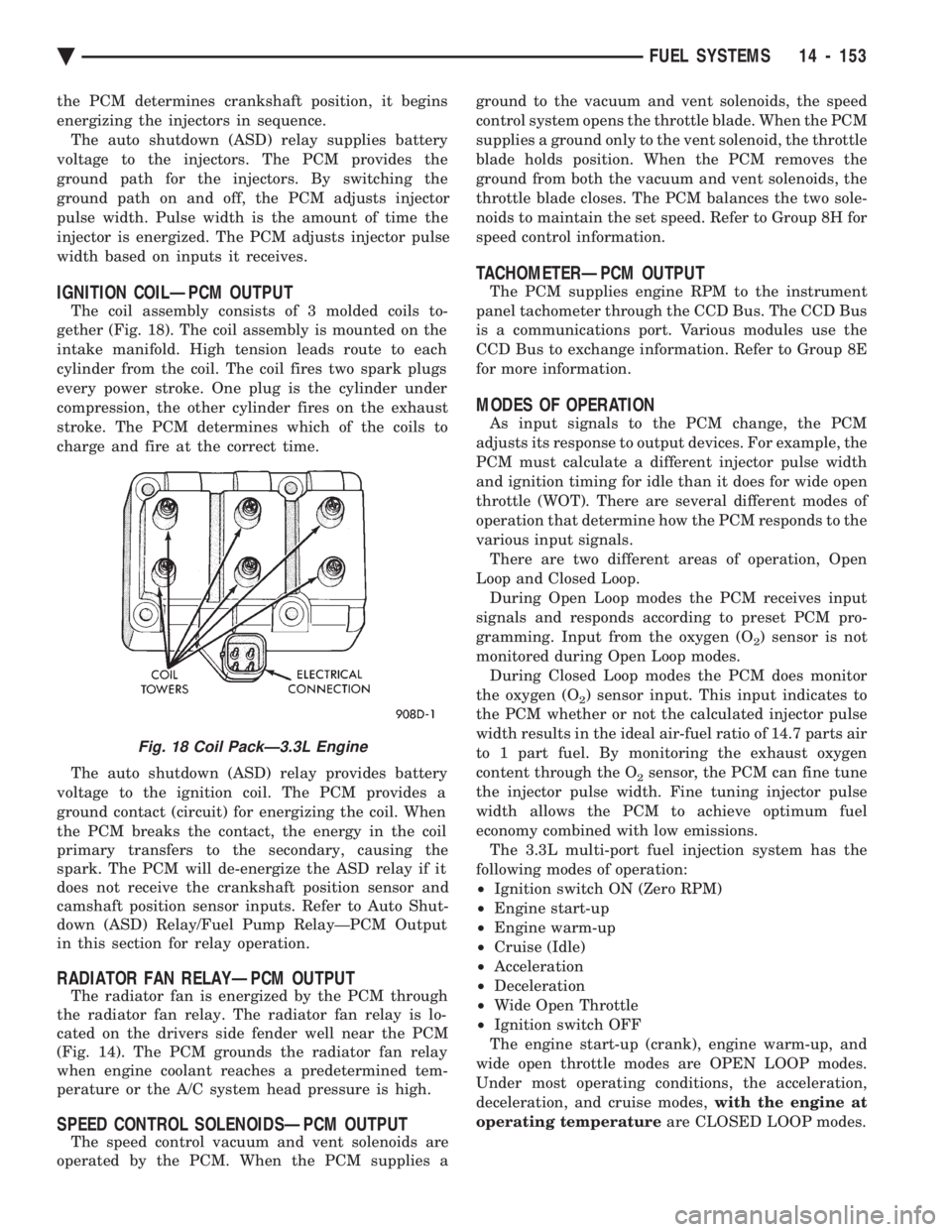
The coil assembly consists of 3 molded coils to-
gether (Fig. 18). The coil assembly is mounted on the
intake manifold. High tension leads route to each
cylinder from the coil. The coil fires two spark plugs
every power stroke. One plug is the cylinder under
compression, the other cylinder fires on the exhaust
stroke. The PCM determines which of the coils to
charge and fire at the correct time.
The auto shutdown (ASD) relay provides battery
voltage to the ignition coil. The PCM provides a
ground contact (circuit) for energizing the coil. When
the PCM breaks the contact, the energy in the coil
primary transfers to the secondary, causing the
spark. The PCM will de-energize the ASD relay if it
does not receive the crankshaft position sensor and
camshaft position sensor inputs. Refer to Auto Shut-
down (ASD) Relay/Fuel Pump RelayÐPCM Output
in this section for relay operation.
RADIATOR FAN RELAYÐPCM OUTPUT
The radiator fan is energized by the PCM through
the radiator fan relay. The radiator fan relay is lo-
cated on the drivers side fender well near the PCM
(Fig. 14). The PCM grounds the radiator fan relay
when engine coolant reaches a predetermined tem-
perature or the A/C system head pressure is high.
SPEED CONTROL SOLENOIDSÐPCM OUTPUT
The speed control vacuum and vent solenoids are
operated by the PCM. When the PCM supplies a ground to the vacuum and vent solenoids, the speed
control system opens the throttle blade. When the PCM
supplies a ground only to the vent solenoid, the throttle
blade holds position. When the PCM removes the
ground from both the vacuum and vent solenoids, the
throttle blade closes. The PCM balances the two sole-
noids to maintain the set speed. Refer to Group 8H for
speed control information.
TACHOMETERÐPCM OUTPUT
The PCM supplies engine RPM to the instrument
panel tachometer through the CCD Bus. The CCD Bus
is a communications port. Various modules use the
CCD Bus to exchange information. Refer to Group 8E
for more information.
MODES OF OPERATION
As input signals to the PCM change, the PCM
adjusts its response to output devices. For example, the
PCM must calculate a different injector pulse width
and ignition timing for idle than it does for wide open
throttle (WOT). There are several different modes of
operation that determine how the PCM responds to the
various input signals. There are two different areas of operation, Open
Loop and Closed Loop. During Open Loop modes the PCM receives input
signals and responds according to preset PCM pro-
gramming. Input from the oxygen (O
2) sensor is not
monitored during Open Loop modes. During Closed Loop modes the PCM does monitor
the oxygen (O
2) sensor input. This input indicates to
the PCM whether or not the calculated injector pulse
width results in the ideal air-fuel ratio of 14.7 parts air
to 1 part fuel. By monitoring the exhaust oxygen
content through the O
2sensor, the PCM can fine tune
the injector pulse width. Fine tuning injector pulse
width allows the PCM to achieve optimum fuel
economy combined with low emissions. The 3.3L multi-port fuel injection system has the
following modes of operation:
² Ignition switch ON (Zero RPM)
² Engine start-up
² Engine warm-up
² Cruise (Idle)
² Acceleration
² Deceleration
² Wide Open Throttle
² Ignition switch OFF
The engine start-up (crank), engine warm-up, and
wide open throttle modes are OPEN LOOP modes.
Under most operating conditions, the acceleration,
deceleration, and cruise modes, with the engine at
operating temperature are CLOSED LOOP modes.
Fig. 18 Coil PackÐ3.3L Engine
Ä FUEL SYSTEMS 14 - 153
Page 1906 of 2438
S/C Vacuum Solenoid
A/C Clutch Relay
EGR Solenoid
Auto Shutdown Relay
Radiator Fan Relay
Purge Solenoid
Malfunction Indicator Lamp (Check Engine Lamp)
STATE DISPLAY SENSORS
Connect the DRBII scan tool to the vehicle and ac-
cess the State Display screen. Then access Sensor
Display. The following is a list of the engine control
system functions accessible through the Sensor Dis-
play screen. Oxygen Sensor Signal
Engine Coolant Temperature
Engine Coolant Temp Sensor
Throttle Position
Minimum Throttle
Battery Voltage
MAP Sensor Reading
Idle Air Control Motor Position
Adaptive Fuel Factor
Barometric Pressure
Min Airflow Idle Spd (speed)
Engine Speed
DIS Sensor Status
Fault #1 Key-On Info
Module Spark Advance
Speed Control Target
Fault #2 Key-on Info
Fault #3 Key-on Info
Speed Control Status
Speed Control Switch Voltage
Charging System Goal
Theft Alarm Status
Map Sensor Voltage
Vehicle Speed
Oxygen Sensor State
MAP Gauge Reading
Throttle Opening (percentage)
Total Spark Advance
CIRCUIT ACTUATION TEST MODE
The circuit actuation test mode checks for proper
operation of output circuits or devices which the pow-
ertrain control module (PCM) cannot internally rec-
ognize. The PCM can attempt to activate these
outputs and allow an observer to verify proper oper-
ation. Most of the tests provide an audible or visual
indication of device operation (click of relay contacts,
spray fuel, etc.). Except for intermittent conditions, if
a device functions properly during testing, assume
the device, its associated wiring, and driver circuit
working correctly.
OBTAINING CIRCUIT ACTUATION TEST
Connect the DRBII scan tool to the vehicle and ac-
cess the Actuators screen. The following is a list of
the engine control system functions accessible
through Actuators screens. Stop All Tests
Ignition Coil #1
Ignition Coil #2
Ignition Coil #3
Fuel Injector #1
Fuel Injector #2
Fuel Injector #3
Fuel Injector #4
Fuel Injector #5
Fuel Injector #6
Idle Air Control Motor Open/Close
Radiator Fan Relay
A/C Clutch Relay
Auto Shutdown Relay
EVAP Purge Solenoid
S/C Servo Solenoids
Generator Field
EGR Solenoid
All Solenoids/Relays
ASD Fuel System Test
Speed Control Vacuum Solenoid
Speed Control Vent Solenoid
THROTTLE BODY MINIMUM AIR FLOW CHECK
PROCEDURE
(1) Warm engine in Park or Neutral until the cool-
ing fan has cycled on and off at least once. (2) Ensure that all accessories are off.
(3) Shut off engine.
(4) Disconnect the PCV valve hose from the intake
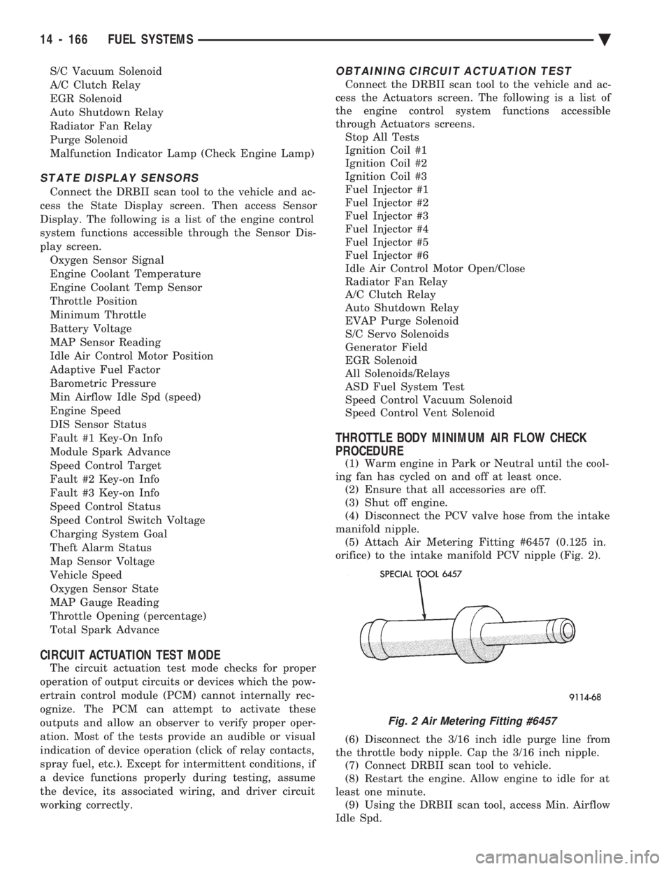
manifold nipple. (5) Attach Air Metering Fitting #6457 (0.125 in.
orifice) to the intake manifold PCV nipple (Fig. 2).
(6) Disconnect the 3/16 inch idle purge line from
the throttle body nipple. Cap the 3/16 inch nipple. (7) Connect DRBII scan tool to vehicle.
(8) Restart the engine. Allow engine to idle for at
least one minute. (9) Using the DRBII scan tool, access Min. Airflow
Idle Spd.
Fig. 2 Air Metering Fitting #6457
14 - 166 FUEL SYSTEMS Ä
Page 1995 of 2438
THREE SPEED TORQUEFLITE AUTOMATIC TRANSAXLE INDEX
page page
Accumulator-Recondition ................... 67
Aluminum Thread Repair ................... 48
Assembly Subassembly Installation ........... 57
Band Adjustment ......................... 47
Bearing Adjustment Procedures .............. 81
Clutch and Servo Air Pressure Tests .......... 43
Differential Repair ........................ 76
Disassembly Subassembly Removal .......... 50
Fluid and Filter Change .................... 40
Fluid Drain and Refill ..................... 40
Fluid Leakage-Transaxle Torque Converter Housing Area .......................... 44
Fluid Level and Condition .................. 40
Front Clutch-Recondition ................... 62
Front Planetary & Annulus Gear-Recondition .... 65
Gearshift Linkage Adjustment ............... 46
General Information ....................... 35
Governor ............................... 48
Hydraulic Control Pressure Adjustments ....... 47
Hydraulic Pressure Tests ................... 42
Kickdown Servo (Controlled Load)-Recondition . . 67 Low/Reverse Servo-Recondition
.............. 66
Oil Cooler Flow Check .................... 48
Oil Coolers and Tubes Reverse Flushing ...... 48
Oil Pump-Recondition ..................... 62
Output Shaft Repair ...................... 71
Park/Neutral Position and Back-Up Lamp Switch . 47
Parking Pawl ............................ 71
Pump Oil Seal-Replacement ................ 61
Rear Clutch-Recondition ................... 64
Road Test .............................. 40
Selection of Lubricant ..................... 40
Special Additives ......................... 40
Three Speed Torqueflite General Diagnosis ..... 36
Throttle Pressure Linkage Adjustment ......... 46
Torque Converter Clutch Solenoid Wiring Connector ............................ 40
Transaxle and Torque Converter Removal ...... 48
Transfer Shaft Repair ..................... 68
Valve Body-Recondition .................... 57
Vehicle Speed Sensor Pinion Gear ........... 47
GENERAL INFORMATION
Safety goggles should be worn at all times
when working on these transaxles. This transaxle combines a fully automatic 3 speed
transmission, final drive gearing, and differential into
a front wheel drive system. The unit is a Metric
design. The identification markings and usage of the
transaxle are charted in Diagnosis and Tests. Transaxle operation requirements are differ-
ent for each vehicle and engine combination and
some internal parts will be different to provide
for this. Therefore, when replacing parts, refer to
the seven digit part number stamped on rear of
the transaxle oil pan flange. Within this transaxle, there are 3 primary areas:
(1) Main center line plus valve body.
(2) Transfer shaft center line (includes governor and
parking sprag). (3) Differential center line. Center distances be-
tween the main rotating parts in these 3 areas are held
precise. This maintains a low noise level through
smooth accurate mesh of the gears. The torque converter, transaxle area, and differential
are housed in an integral aluminum die casting. The
differential oil sump is common with thetransaxle
sump. Separate filling of the differential is NOT nec-
essary. The torque converter is attached to the crankshaft
through a flexible driving plate. Cooling of the con-
verter is accomplished by circulating the transaxle
fluid through an oil-to-water type cooler located in the
radiator side tank and/or an oil-to air heat ex- changer. The torque converter assembly is a sealed
unit that cannot be disassembled.
The transaxle fluid is filtered by an internal filter
attached to the lower side of the valve body assem-
bly. Engine torque is transmitted to the torque con-
verter then, through the input shaft to multiple-disc
clutches in the transaxle. The power flow depends on
the application of the clutches and bands. Refer to
Elements in Use Chart in Diagnosis and Tests sec-
tion. The transaxle consists of two multiple-disc
clutches, an overrunning clutch, two servos, a hy-
draulic accumulator, two bands, and two planetary
gear sets. They provide three forward ratios and a re-
verse ratio. The common sun gear of the planetary
gear sets is connected to the front clutch by a driving
shell. The drive shell is splined to the sun gear and
to the front clutch retainer. The hydraulic system
consists of an oil pump, and a single valve body
which contains all of the valves except the governor
valves. The transaxle sump and differential sump are
both vented through the dipstick.Output torque
from the main center line is delivered through heli-
cal gears to the transfer shaft.This gear set is a
factor of the final drive (axle) ratio. The shaft also
carries the governor and parking sprag. An integral
helical gear on the transfer shaft drives the differen-
tial ring gear. The final drive gearing is completed
with one of three gear sets producing overall top gear
ratios of 2.78, 3.02, or 3.22 depending on model and
application.
Ä TRANSAXLE 21 - 35
Page 2008 of 2438
GOVERNOR
To service the governor assembly in the vehicle, it
is not necessary to remove the transfer gear cover,
transfer gear, and governor support. The governor
may be serviced by removing the transaxle oil pan
and valve body assembly. With the oil pan and valve
body removed, the governor may be unbolted from
the governor support and removed. When cleaning or assembling the governor, make
sure the governor valves move freely in the bores of
the governor body.
ALUMINUM THREAD REPAIR
Damaged or worn threads in the aluminum tran-
saxle case and valve body can be repaired by the use
of Heli-Coils, or equivalent. This repair consists of
drilling out the worn-out damaged threads. Then tap-
ping the hole with a Heli-Coil tap, or equivalent, and
installing a Heli-Coil insert, or equivalent, into the
hole. This brings the hole back to its original thread
size. Heli-Coil, or equivalent, tools and inserts are
readily available from most automotive parts suppli-
ers.
OIL COOLERS AND TUBES REVERSE FLUSHING
When a transaxle failure has contaminated the
fluid, the oil cooler(s) must be flushed. The torque
converter must be replaced with an exchange unit.
This will insure that metal particles or sludged oil
are not transferred back into the reconditioned (or
replaced) transaxle.
CAUTION: If vehicle is equipped with two oil cool-
ers (one in the radiator tank, one in front of the ra-
diator) they must be flushed separately. Do not
attempt to flush both coolers at one time.
(1) Disconnect the cooler lines at the transmission.
(2) Using a hand suction gun filled with mineral
spirits, reverse flush the cooler. Force mineral spirits
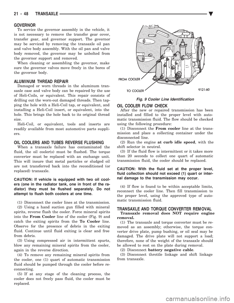
into the From Cooler line of the cooler (Fig. 9) and
catch the exiting spirits from the To Coolerline.
Observe for the presence of debris in the exiting
fluid. Continue until fluid exiting is clear and free
from debris. (3) Using compressed air in intermittent spurts,
blow any remaining mineral spirits from the cooler,
again in the reverse direction. (4) To remove any remaining mineral spirits from
the cooler, one (1) quart of automatic transmission
fluid should be pumped through the cooler before re-
connecting. (5) If at any stage of the cleaning process, the
cooler does not freely pass fluid, the cooler must be
replaced.
OIL COOLER FLOW CHECK
After the new or repaired transmission has been
installed and filled to the proper level with auto-
matic transmission fluid. The flow should be checked
using the following procedure: (1) Disconnect the From coolerline at the trans-
mission and place a collecting container under the
disconnected line. (2) Run the engine at curb idle speed , with the
shift selector in neutral. (3) If the fluid flow is intermittent or it takes more
than 20 seconds to collect one quart of automatic
transmission fluid, the cooler should be replaced.
CAUTION: With the fluid set at the proper level,
fluid collection should not exceed (1) quart or inter-
nal damage to the transmission may occur.
(4) If flow is found to be within acceptable limits,
reconnect the cooler line. Then fill transmission to
the proper level, using the approved type of auto-
matic transmission fluid.
TRANSAXLE AND TORQUE CONVERTER REMOVAL
Transaxle removal does NOT require engine
removal. (1) The transaxle and torque converter must be re-
moved as an assembly; otherwise, the torque con-
verter drive plate, pump bushing, or oil seal may be
damaged. The drive plate will not support a load;
therefore, none of the weight of the transaxle should
be allowed to rest on the plate during removal. (2) Disconnect battery negative cable .
(3) Disconnect throttle linkage and shift linkage
from transaxle.
Fig. 9 Cooler Line Identification
21 - 48 TRANSAXLE Ä
Page 2059 of 2438
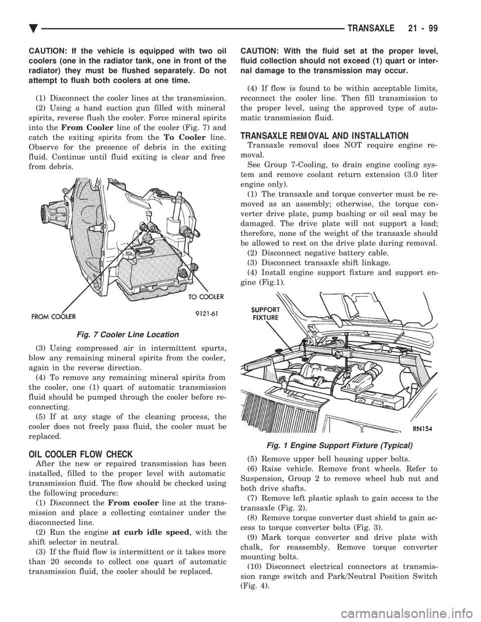
CAUTION: If the vehicle is equipped with two oil
coolers (one in the radiator tank, one in front of the
radiator) they must be flushed separately. Do not
attempt to flush both coolers at one time. (1) Disconnect the cooler lines at the transmission.
(2) Using a hand suction gun filled with mineral
spirits, reverse flush the cooler. Force mineral spirits
into the From Cooler line of the cooler (Fig. 7) and
catch the exiting spirits from the To Coolerline.
Observe for the presence of debris in the exiting
fluid. Continue until fluid exiting is clear and free
from debris.
(3) Using compressed air in intermittent spurts,
blow any remaining mineral spirits from the cooler,
again in the reverse direction. (4) To remove any remaining mineral spirits from
the cooler, one (1) quart of automatic transmission
fluid should be pumped through the cooler before re-
connecting. (5) If at any stage of the cleaning process, the
cooler does not freely pass fluid, the cooler must be
replaced.
OIL COOLER FLOW CHECK
After the new or repaired transmission has been
installed, filled to the proper level with automatic
transmission fluid. The flow should be checked using
the following procedure: (1) Disconnect the From coolerline at the trans-
mission and place a collecting container under the
disconnected line. (2) Run the engine at curb idle speed , with the
shift selector in neutral. (3) If the fluid flow is intermittent or it takes more
than 20 seconds to collect one quart of automatic
transmission fluid, the cooler should be replaced. CAUTION: With the fluid set at the proper level,
fluid collection should not exceed (1) quart or inter-
nal damage to the transmission may occur.
(4) If flow is found to be within acceptable limits,
reconnect the cooler line. Then fill transmission to
the proper level, using the approved type of auto-
matic transmission fluid.
TRANSAXLE REMOVAL AND INSTALLATION
Transaxle removal does NOT require engine re-
moval. See Group 7-Cooling, to drain engine cooling sys-
tem and remove coolant return extension (3.0 liter
engine only). (1) The transaxle and torque converter must be re-
moved as an assembly; otherwise, the torque con-
verter drive plate, pump bushing or oil seal may be
damaged. The drive plate will not support a load;
therefore, none of the weight of the transaxle should
be allowed to rest on the drive plate during removal. (2) Disconnect negative battery cable.
(3) Disconnect transaxle shift linkage.
(4) Install engine support fixture and support en-
gine (Fig.1).
(5) Remove upper bell housing upper bolts.
(6) Raise vehicle. Remove front wheels. Refer to
Suspension, Group 2 to remove wheel hub nut and
both drive shafts. (7) Remove left plastic splash to gain access to the
transaxle (Fig. 2). (8) Remove torque converter dust shield to gain ac-
cess to torque converter bolts (Fig. 3). (9) Mark torque converter and drive plate with
chalk, for reassembly. Remove torque converter
mounting bolts. (10) Disconnect electrical connectors at transmis-
sion range switch and Park/Neutral Position Switch
(Fig. 4).
Fig. 7 Cooler Line Location
Fig. 1 Engine Support Fixture (Typical)
Ä TRANSAXLE 21 - 99
Page 2168 of 2438
(5) With assistance of a helper at the opposite side
of the vehicle to support the hood, remove the bottom
hood to hinge attaching bolts. Separate the hood
from the vehicle.
HOOD INSTALLATION
Reverse the preceding operation.
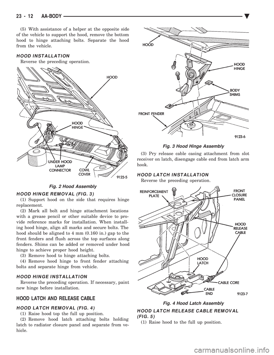
HOOD HINGE REMOVAL (FIG. 3)
(1) Support hood on the side that requires hinge
replacement. (2) Mark all bolt and hinge attachment locations
with a grease pencil or other suitable device to pro-
vide reference marks for installation. When install-
ing hood hinge, align all marks and secure bolts. The
hood should be aligned to 4 mm (0.160 in.) gap to the
front fenders and flush across the top surfaces along
fenders. Shims can be added or removed under hood
hinge to achieve proper hood height. (3) Remove hood to hinge attaching bolts.
(4) Remove hood hinge to front fender attaching
bolts and separate hinge from vehicle.
HOOD HINGE INSTALLATION
Reverse the preceding operation. If necessary, paint
new hinge before installation.
HOOD LATCH AND RELEASE CABLE
HOOD LATCH REMOVAL (FIG. 4)
(1) Raise hood top the full up position.
(2) Remove hood latch attaching bolts holding
latch to radiator closure panel and separate from ve-
hicle. (3) Pry release cable casing attachment from slot
receiver on latch, disengage cable end from latch arm
hook.
HOOD LATCH INSTALLATION
Reverse the preceding operation.
HOOD LATCH RELEASE CABLE REMOVAL (FIG. 5)
(1) Raise hood to the full up position.
Fig. 2 Hood Assembly
Fig. 3 Hood Hinge Assembly
Fig. 4 Hood Latch Assembly
23 - 12 AA-BODY Ä
Page 2169 of 2438
(2) Remove push-in fasteners holding hood latch
cover to radiator closure panel and separate cover
from vehicle. (3) Disconnect hood release cable casing and cable
end from hood latch assembly. Refer to Hood Latch
Removal procedure in this section. (4) Remove hood latch release cable handle attach-
ing bolts from under left lower edge of instrument
panel. (5) Disengage release cable rubber grommet from
engine compartment dash panel behind instrument
panel. (6) Rout cable assembly through engine compart-
ment around battery, under fender lip, under relay
bank, and under wiring harnesses, toward dash
panel. Push cable through access hole in dash panel
under the brake master cylinder, into passenger com-
partment.
HOOD LATCH RELEASE CABLE INSTALLATION
Reverse the preceding operation.
COWL COVER
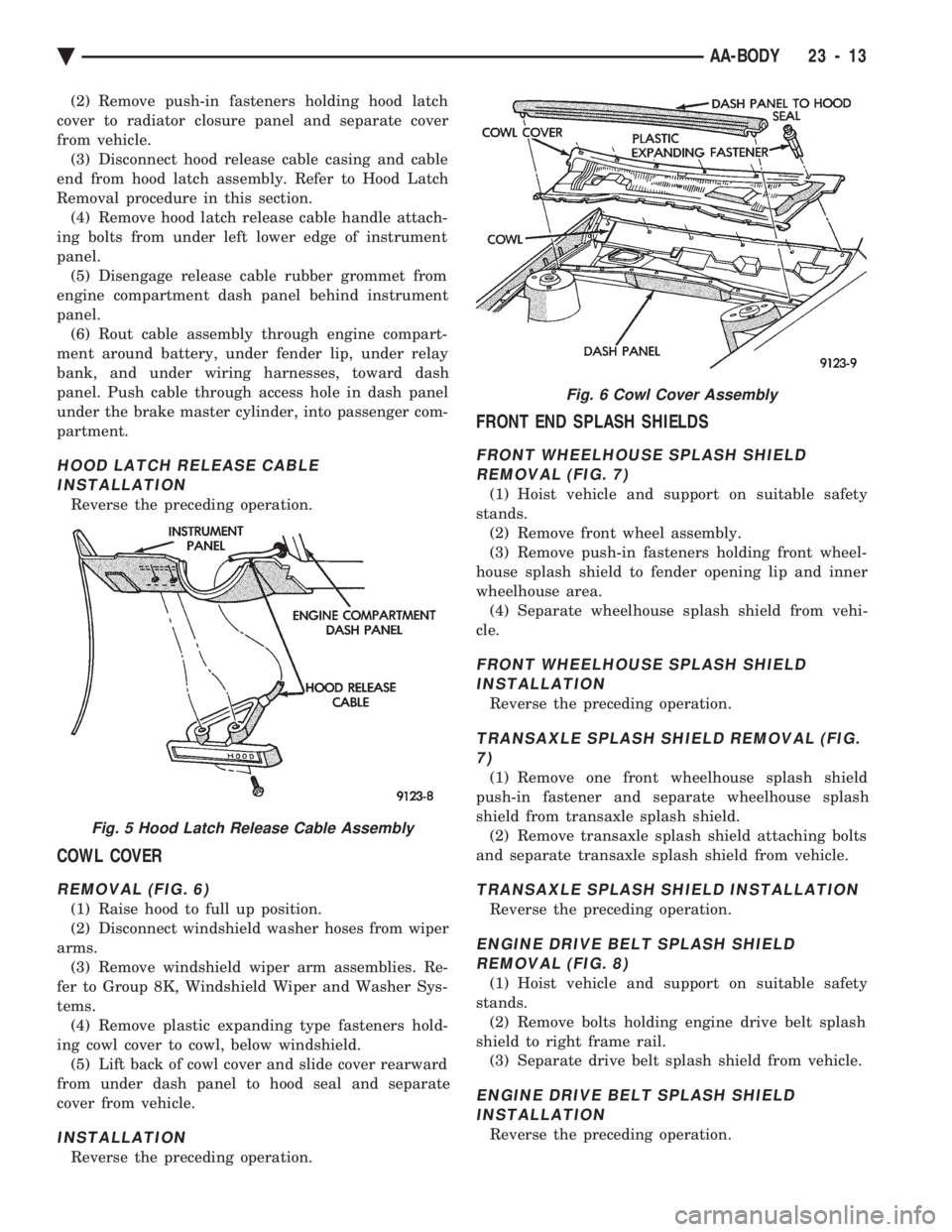
REMOVAL (FIG. 6)
(1) Raise hood to full up position.
(2) Disconnect windshield washer hoses from wiper
arms. (3) Remove windshield wiper arm assemblies. Re-
fer to Group 8K, Windshield Wiper and Washer Sys-
tems. (4) Remove plastic expanding type fasteners hold-
ing cowl cover to cowl, below windshield. (5) Lift back of cowl cover and slide cover rearward
from under dash panel to hood seal and separate
cover from vehicle.
INSTALLATION
Reverse the preceding operation.
FRONT END SPLASH SHIELDS
FRONT WHEELHOUSE SPLASH SHIELD REMOVAL (FIG. 7)
(1) Hoist vehicle and support on suitable safety
stands. (2) Remove front wheel assembly.
(3) Remove push-in fasteners holding front wheel-
house splash shield to fender opening lip and inner
wheelhouse area. (4) Separate wheelhouse splash shield from vehi-
cle.
FRONT WHEELHOUSE SPLASH SHIELD INSTALLATION
Reverse the preceding operation.
TRANSAXLE SPLASH SHIELD REMOVAL (FIG.7)
(1) Remove one front wheelhouse splash shield
push-in fastener and separate wheelhouse splash
shield from transaxle splash shield. (2) Remove transaxle splash shield attaching bolts
and separate transaxle splash shield from vehicle.
TRANSAXLE SPLASH SHIELD INSTALLATION
Reverse the preceding operation.
ENGINE DRIVE BELT SPLASH SHIELD REMOVAL (FIG. 8)
(1) Hoist vehicle and support on suitable safety
stands. (2) Remove bolts holding engine drive belt splash
shield to right frame rail. (3) Separate drive belt splash shield from vehicle.
ENGINE DRIVE BELT SPLASH SHIELDINSTALLATION
Reverse the preceding operation.
Fig. 5 Hood Latch Release Cable Assembly
Fig. 6 Cowl Cover Assembly
Ä AA-BODY 23 - 13
Page 2170 of 2438
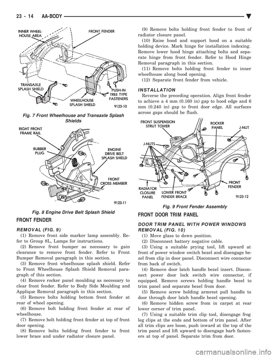
FRONT FENDER
REMOVAL (FIG. 9)
(1) Remove front side marker lamp assembly. Re-
fer to Group 8L, Lamps for instructions. (2) Remove front bumper as necessary to gain
clearance to remove front fender. Refer to Front
Bumper Removal paragraph in this section. (3) Remove front wheelhouse splash shield. Refer
to Front Wheelhouse Splash Shield Removal para-
graph of this section. (4) Remove rocker panel moulding as necessary to
clear front fender. Refer to Body Side Moulding and
Applique Removal paragraph in this section. (5) Remove bolts holding bottom front fender at
rear of wheel opening. (6) Remove bolt holding front fender at rear of
wheelhouse. (7) Remove bolt holding front fender at top of front
door opening. (8) Remove bolts holding front fender to front
lower brace and under radiator closure panel. (9) Remove bolts holding front fender to front of
radiator closure panel. (10) Raise hood and support hood on a suitable
holding device. Mark hinge for installation indexing.
Remove lower hood hinge attaching bolts and sepa-
rate hinge from front fender. Refer to Hood Hinge
Removal paragraph in this section. (11) Remove bolts holding front fender to inner
wheelhouse along hood opening. (12) Separate front fender from vehicle.
INSTALLATION
Reverse the preceding operation. Align front fender
to achiev ea4mm (0.160 in) gap to hood edge and 6
mm (0.240 in) gap to front door edge. All surfaces
across gaps should be flush.
FRONT DOOR TRIM PANEL
DOOR TRIM PANEL WITH POWER WINDOWS REMOVAL (FIG. 10)
(1) Move glass to down position.
(2) Disconnect battery negative cable.
(3) Using a suitable prying tool, lift upward at
front of power window switch bezel and disengage be-
zel from clip in door panel. Disconnect wire connector
from back of switch. (4) Remove door latch handle bezel insert. Discon-
nect power door lock switch wire connector, if
equipped. Remove screws holding handle bezel to
trim panel and separate bezel from door. (5) Remove screw holding armrest pull handle to
door through door latch handle bezel opening. (6) Remove hidden screw from in carpet at rear
lower corner of trim panel. (7) Using a suitable trim clip tool, disengage frog
leg clips at the ends and bottom of trim panel. After
all trim clips are loose, push inward at the top of the
trim panel and lift upward to disengage barb fasten-
ers at top of panel. Separate trim from door.
Fig. 7 Front Wheelhouse and Transaxle Splash Shields
Fig. 8 Engine Drive Belt Splash Shield
Fig. 9 Front Fender Assembly
23 - 14 AA-BODY Ä