1993 CHEVROLET PLYMOUTH ACCLAIM radiator
[x] Cancel search: radiatorPage 2254 of 2438
ing hood, align all marks and secure bolts. The hood
should be aligned to 4 mm (0.160 in.) gap to the front
fenders and flush across the top surfaces along fend-
ers.(4) Remove the top hood to hinge attaching bolts
and loosen the bottom bolts until they can be re-
moved by hand. (5) With assistance of a helper at the opposite side
of the vehicle to support the hood, remove the bottom
hood to hinge attaching bolts. Separate the hood
from the vehicle.
HOOD INSTALLATION
Reverse the preceding operation.
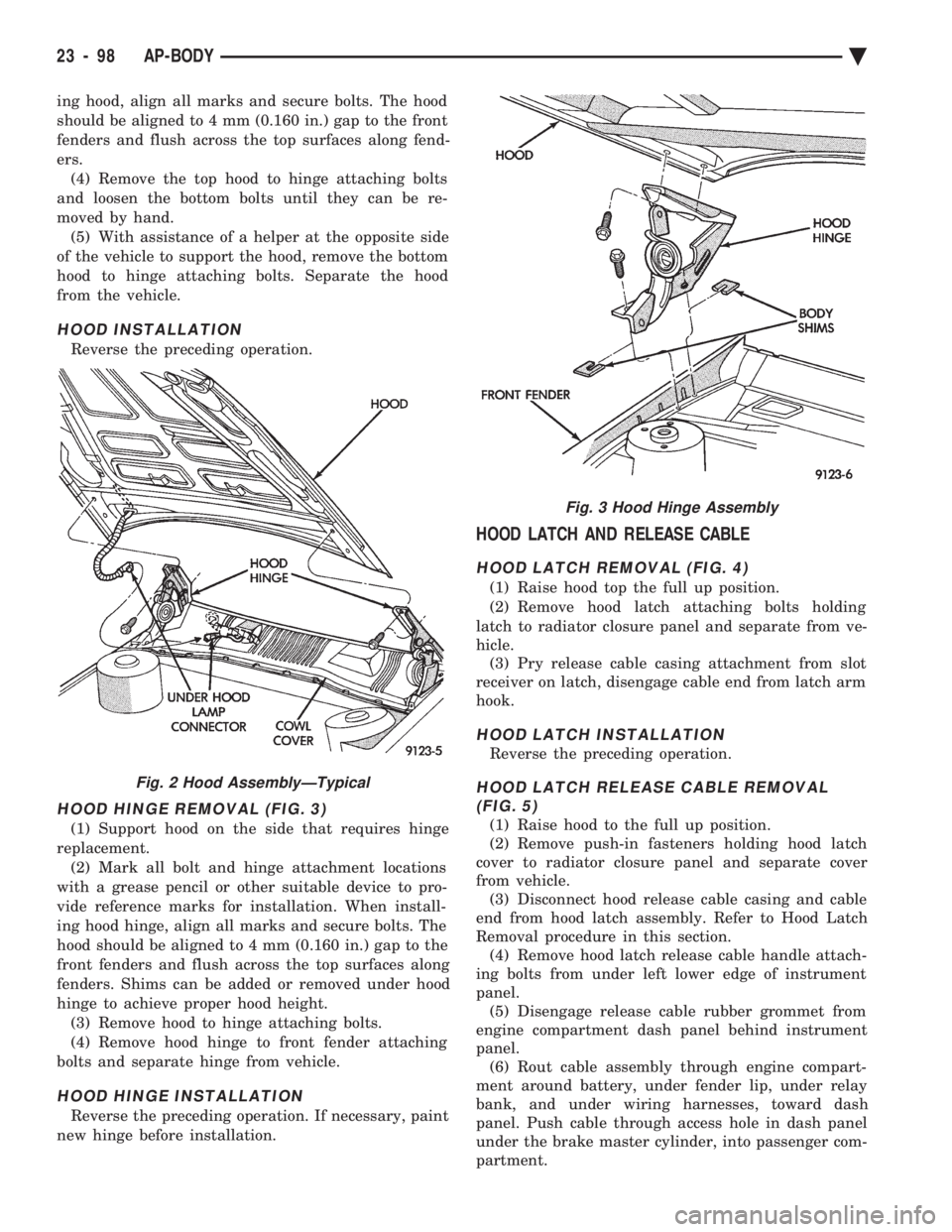
HOOD HINGE REMOVAL (FIG. 3)
(1) Support hood on the side that requires hinge
replacement. (2) Mark all bolt and hinge attachment locations
with a grease pencil or other suitable device to pro-
vide reference marks for installation. When install-
ing hood hinge, align all marks and secure bolts. The
hood should be aligned to 4 mm (0.160 in.) gap to the
front fenders and flush across the top surfaces along
fenders. Shims can be added or removed under hood
hinge to achieve proper hood height. (3) Remove hood to hinge attaching bolts.
(4) Remove hood hinge to front fender attaching
bolts and separate hinge from vehicle.
HOOD HINGE INSTALLATION
Reverse the preceding operation. If necessary, paint
new hinge before installation.
HOOD LATCH AND RELEASE CABLE
HOOD LATCH REMOVAL (FIG. 4)
(1) Raise hood top the full up position.
(2) Remove hood latch attaching bolts holding
latch to radiator closure panel and separate from ve-
hicle. (3) Pry release cable casing attachment from slot
receiver on latch, disengage cable end from latch arm
hook.
HOOD LATCH INSTALLATION
Reverse the preceding operation.
HOOD LATCH RELEASE CABLE REMOVAL (FIG. 5)
(1) Raise hood to the full up position.
(2) Remove push-in fasteners holding hood latch
cover to radiator closure panel and separate cover
from vehicle. (3) Disconnect hood release cable casing and cable
end from hood latch assembly. Refer to Hood Latch
Removal procedure in this section. (4) Remove hood latch release cable handle attach-
ing bolts from under left lower edge of instrument
panel. (5) Disengage release cable rubber grommet from
engine compartment dash panel behind instrument
panel. (6) Rout cable assembly through engine compart-
ment around battery, under fender lip, under relay
bank, and under wiring harnesses, toward dash
panel. Push cable through access hole in dash panel
under the brake master cylinder, into passenger com-
partment.
Fig. 2 Hood AssemblyÐTypical
Fig. 3 Hood Hinge Assembly
23 - 98 AP-BODY Ä
Page 2290 of 2438
HOOD ORNAMENT AY/P-S
REMOVAL (FIG. 2)
(1) Remove grille.
(2) Locate hood ornament spring under grille open-
ing panel header. (3) Compress hood ornament spring enough to
clear hooks on end of retaining wire. (4) Squeeze retainer wire hooks together and push
hooks inside spring. (5) Rotate spring counterclockwise to separate
spring from retainer. (6) Separate hood ornament from grille opening
panel.
INSTALLATION
Reverse the preceding operation.
GRILLE OPENING PANEL AY/P BODY
For service procedures for headlamp related compo-
nents refer to Group 8L, Lamps.
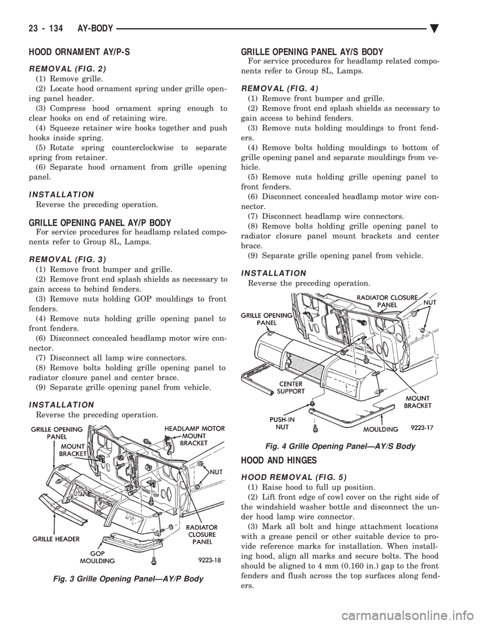
REMOVAL (FIG. 3)
(1) Remove front bumper and grille.
(2) Remove front end splash shields as necessary to
gain access to behind fenders. (3) Remove nuts holding GOP mouldings to front
fenders. (4) Remove nuts holding grille opening panel to
front fenders. (6) Disconnect concealed headlamp motor wire con-
nector. (7) Disconnect all lamp wire connectors.
(8) Remove bolts holding grille opening panel to
radiator closure panel and center brace. (9) Separate grille opening panel from vehicle.
INSTALLATION
Reverse the preceding operation.
GRILLE OPENING PANEL AY/S BODY
For service procedures for headlamp related compo-
nents refer to Group 8L, Lamps.
REMOVAL (FIG. 4)
(1) Remove front bumper and grille.
(2) Remove front end splash shields as necessary to
gain access to behind fenders. (3) Remove nuts holding mouldings to front fend-
ers. (4) Remove bolts holding mouldings to bottom of
grille opening panel and separate mouldings from ve-
hicle. (5) Remove nuts holding grille opening panel to
front fenders. (6) Disconnect concealed headlamp motor wire con-
nector. (7) Disconnect headlamp wire connectors.
(8) Remove bolts holding grille opening panel to
radiator closure panel mount brackets and center
brace. (9) Separate grille opening panel from vehicle.
INSTALLATION
Reverse the preceding operation.
HOOD AND HINGES
HOOD REMOVAL (FIG. 5)
(1) Raise hood to full up position.
(2) Lift front edge of cowl cover on the right side of
the windshield washer bottle and disconnect the un-
der hood lamp wire connector. (3) Mark all bolt and hinge attachment locations
with a grease pencil or other suitable device to pro-
vide reference marks for installation. When install-
ing hood, align all marks and secure bolts. The hood
should be aligned to 4 mm (0.160 in.) gap to the front
fenders and flush across the top surfaces along fend-
ers.
Fig. 3 Grille Opening PanelÐAY/P Body
Fig. 4 Grille Opening PanelÐAY/S Body
23 - 134 AY-BODY Ä
Page 2291 of 2438
(4) Remove the top hood to hinge bolts and loosen
the bottom bolts until they can be removed by hand. (5) With assistance of a helper at the opposite side
of the vehicle to support the hood, remove the bottom
hood to hinge bolts. Separate the hood from the ve-
hicle.
HOOD INSTALLATION
Reverse the preceding operation.
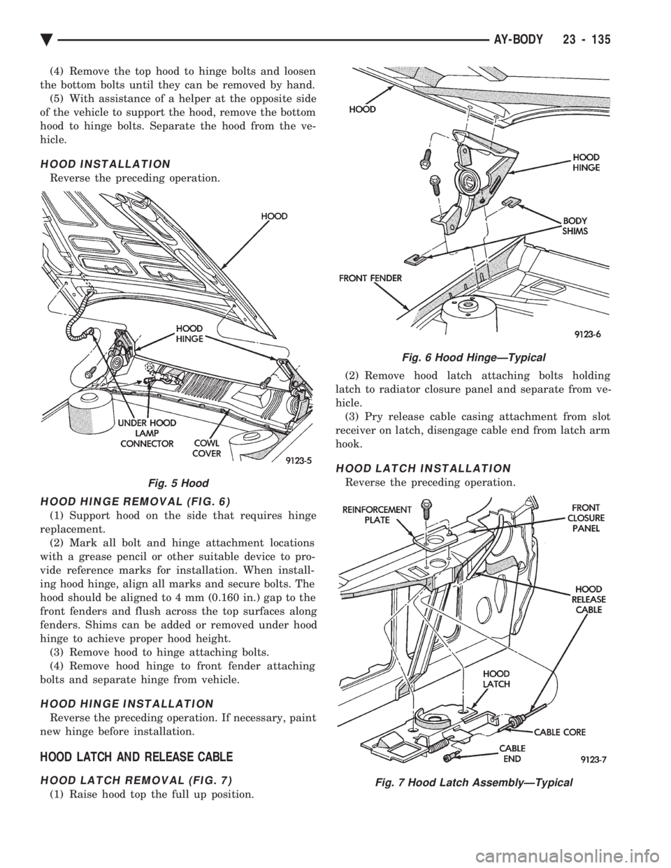
HOOD HINGE REMOVAL (FIG. 6)
(1) Support hood on the side that requires hinge
replacement. (2) Mark all bolt and hinge attachment locations
with a grease pencil or other suitable device to pro-
vide reference marks for installation. When install-
ing hood hinge, align all marks and secure bolts. The
hood should be aligned to 4 mm (0.160 in.) gap to the
front fenders and flush across the top surfaces along
fenders. Shims can be added or removed under hood
hinge to achieve proper hood height. (3) Remove hood to hinge attaching bolts.
(4) Remove hood hinge to front fender attaching
bolts and separate hinge from vehicle.
HOOD HINGE INSTALLATION
Reverse the preceding operation. If necessary, paint
new hinge before installation.
HOOD LATCH AND RELEASE CABLE
HOOD LATCH REMOVAL (FIG. 7)
(1) Raise hood top the full up position. (2) Remove hood latch attaching bolts holding
latch to radiator closure panel and separate from ve-
hicle. (3) Pry release cable casing attachment from slot
receiver on latch, disengage cable end from latch arm
hook.
HOOD LATCH INSTALLATION
Reverse the preceding operation.Fig. 5 Hood
Fig. 6 Hood HingeÐTypical
Fig. 7 Hood Latch AssemblyÐTypical
Ä AY-BODY 23 - 135
Page 2292 of 2438
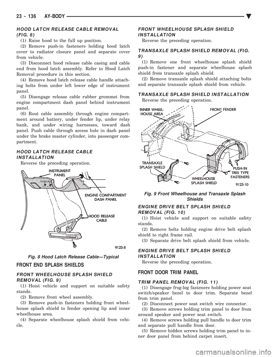
HOOD LATCH RELEASE CABLE REMOVAL (FIG. 8)
(1) Raise hood to the full up position.
(2) Remove push-in fasteners holding hood latch
cover to radiator closure panel and separate cover
from vehicle. (3) Disconnect hood release cable casing and cable
end from hood latch assembly. Refer to Hood Latch
Removal procedure in this section. (4) Remove hood latch release cable handle attach-
ing bolts from under left lower edge of instrument
panel. (5) Disengage release cable rubber grommet from
engine compartment dash panel behind instrument
panel. (6) Rout cable assembly through engine compart-
ment around battery, under fender lip, under relay
bank, and under wiring harnesses, toward dash
panel. Push cable through access hole in dash panel
under the brake master cylinder, into passenger com-
partment.
HOOD LATCH RELEASE CABLE INSTALLATION
Reverse the preceding operation.
FRONT END SPLASH SHIELDS
FRONT WHEELHOUSE SPLASH SHIELDREMOVAL (FIG. 9)
(1) Hoist vehicle and support on suitable safety
stands. (2) Remove front wheel assembly.
(3) Remove push-in fasteners holding front wheel-
house splash shield to fender opening lip and inner
wheelhouse area. (4) Separate wheelhouse splash shield from vehi-
cle.
FRONT WHEELHOUSE SPLASH SHIELD INSTALLATION
Reverse the preceding operation.
TRANSAXLE SPLASH SHIELD REMOVAL (FIG.9)
(1) Remove one front wheelhouse splash shield
push-in fastener and separate wheelhouse splash
shield from transaxle splash shield. (2) Remove transaxle splash shield attaching bolts
and separate transaxle splash shield from vehicle.
TRANSAXLE SPLASH SHIELD INSTALLATION
Reverse the preceding operation.
ENGINE DRIVE BELT SPLASH SHIELD REMOVAL (FIG. 10)
(1) Hoist vehicle and support on suitable safety
stands. (2) Remove bolts holding engine drive belt splash
shield to right frame rail. (3) Separate drive belt splash shield from vehicle.
ENGINE DRIVE BELT SPLASH SHIELDINSTALLATION
Reverse the preceding operation.
FRONT DOOR TRIM PANEL
TRIM PANEL REMOVAL (FIG. 11)
(1) Disengage frog-leg fasteners holding power seat
switch/speaker bezel to door trim. Separate bezel
from trim panel. (2) Disconnect power seat switch wire connector.
(3) Remove screws holding trim panel to door from
around speaker and power seat switch. (4) Remove screws holding pull handle to door trim
and separate pull handle from door. (5) Remove hidden screws holding trim panel to in-
ner door panel from behind carpet insert.
Fig. 8 Hood Latch Release CableÐTypical
Fig. 9 Front Wheelhouse and Transaxle Splash Shields
23 - 136 AY-BODY Ä
Page 2306 of 2438
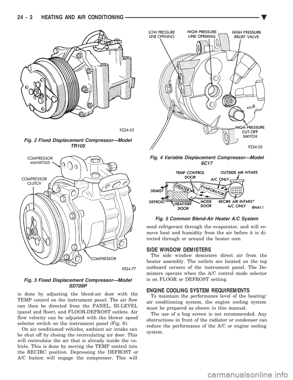
is done by adjusting the blend-air door with the
TEMP control on the instrument panel. The air flow
can then be directed from the PANEL, BI-LEVEL
(panel and floor), and FLOOR-DEFROST outlets. Air
flow velocity can be adjusted with the blower speed
selector switch on the instrument panel (Fig. 6). On air conditioned vehicles, ambient air intake can
be shut off by closing the recirculating air door. This
will recirculate the air that is already inside the ve-
hicle. This is done by moving the TEMP control into
the RECIRC position. Depressing the DEFROST or
A/C button will engage the compressor. This will send refrigerant through the evaporator, and will re-
move heat and humidity from the air before it is di-
rected through or around the heater core.
SIDE WINDOW DEMISTERS
The side window demisters direct air from the
heater assembly. The outlets are located on the top
outboard corners of the instrument panel. The De-
misters operate when the A/C control mode selector
is on FLOOR or DEFROST setting.
ENGINE COOLING SYSTEM REQUIREMENTS
To maintain the performance level of the heating/
air conditioning system, the engine cooling system
must be prepared as shown in this manual. The use of a bug screen is not recommended. Any
obstructions in front of the radiator or condenser can
reduce the performance of the A/C or engine cooling
system.
Fig. 2 Fixed Displacement CompressorÐModel TR105
Fig. 3 Fixed Displacement CompressorÐModelSD709P
Fig. 4 Variable Displacement CompressorÐModel 6C17
Fig. 5 Common Blend-Air Heater A/C System
24 - 2 HEATING AND AIR CONDITIONING Ä
Page 2310 of 2438
HEATER AND A/C PERFORMANCE TESTS
HEATER OUTPUT TEST
PRE-DIAGNOSTIC PREPARATIONS
Review Safety Precautions and Warnings before
performing the following procedures. Check the radiator coolant level, drive belt tension,
and engine vacuum line connections. Also check ra-
diator air flow and radiator fan operation. Start en-
gine and allow to warm up to normal operating
temperature.
WARNING: DO NOT REMOVE RADIATOR CAP
WHEN ENGINE IS HOT, PERSONAL INJURY CAN
RESULT.
If vehicle has been run recently, wait 15 minutes
before removing cap. Place a rag over the cap and
turn it to the first safety stop. Allow pressure to es-
cape through the overflow tube. When the system
stabilizes, remove the cap completely.
MAXIMUM HEATER OUTPUT: TEST AND ACTION
Engine coolant is provided to the heater system by
two 16 mm (5/8 inch inside diameter) heater hoses.
With engine idling at normal running temperature,
set the control to maximum heat, floor, and high
blower setting. Using a test thermometer, check the
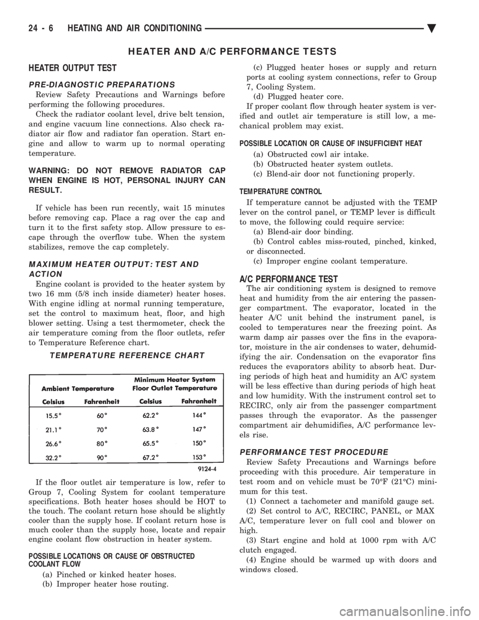
air temperature coming from the floor outlets, refer
to Temperature Reference chart.
If the floor outlet air temperature is low, refer to
Group 7, Cooling System for coolant temperature
specifications. Both heater hoses should be HOT to
the touch. The coolant return hose should be slightly
cooler than the supply hose. If coolant return hose is
much cooler than the supply hose, locate and repair
engine coolant flow obstruction in heater system.
POSSIBLE LOCATIONS OR CAUSE OF OBSTRUCTED
COOLANT FLOW
(a) Pinched or kinked heater hoses.
(b) Improper heater hose routing. (c) Plugged heater hoses or supply and return
ports at cooling system connections, refer to Group
7, Cooling System. (d) Plugged heater core.
If proper coolant flow through heater system is ver-
ified and outlet air temperature is still low, a me-
chanical problem may exist.
POSSIBLE LOCATION OR CAUSE OF INSUFFICIENT HEAT
(a) Obstructed cowl air intake.
(b) Obstructed heater system outlets.
(c) Blend-air door not functioning properly.
TEMPERATURE CONTROL If temperature cannot be adjusted with the TEMP
lever on the control panel, or TEMP lever is difficult
to move, the following could require service: (a) Blend-air door binding.
(b) Control cables miss-routed, pinched, kinked,
or disconnected. (c) Improper engine coolant temperature.A/C PERFORMANCE TEST
The air conditioning system is designed to remove
heat and humidity from the air entering the passen-
ger compartment. The evaporator, located in the
heater A/C unit behind the instrument panel, is
cooled to temperatures near the freezing point. As
warm damp air passes over the fins in the evapora-
tor, moisture in the air condenses to water, dehumid-
ifying the air. Condensation on the evaporator fins
reduces the evaporators ability to absorb heat. Dur-
ing periods of high heat and humidity an A/C system
will be less effective than during periods of high heat
and low humidity. With the instrument control set to
RECIRC, only air from the passenger compartment
passes through the evaporator. As the passenger
compartment air dehumidifies, A/C performance lev-
els rise.
PERFORMANCE TEST PROCEDURE
Review Safety Precautions and Warnings before
proceeding with this procedure. Air temperature in
test room and on vehicle must be 70ÉF (21ÉC) mini-
mum for this test. (1) Connect a tachometer and manifold gauge set.
(2) Set control to A/C, RECIRC, PANEL, or MAX
A/C, temperature lever on full cool and blower on
high. (3) Start engine and hold at 1000 rpm with A/C
clutch engaged. (4) Engine should be warmed up with doors and
windows closed.
TEMPERATURE REFERENCE CHART
24 - 6 HEATING AND AIR CONDITIONING Ä
Page 2325 of 2438
(5) Evacuate and charge the refrigerant system. If
oil loss of 3 ml (1 oz) or greater is suspected, refer to
Oil Level in the Refrigerant Service Procedures sec-
tion.
COMPRESSOR HIGH PRESSURE CUT-OUT SWITCH
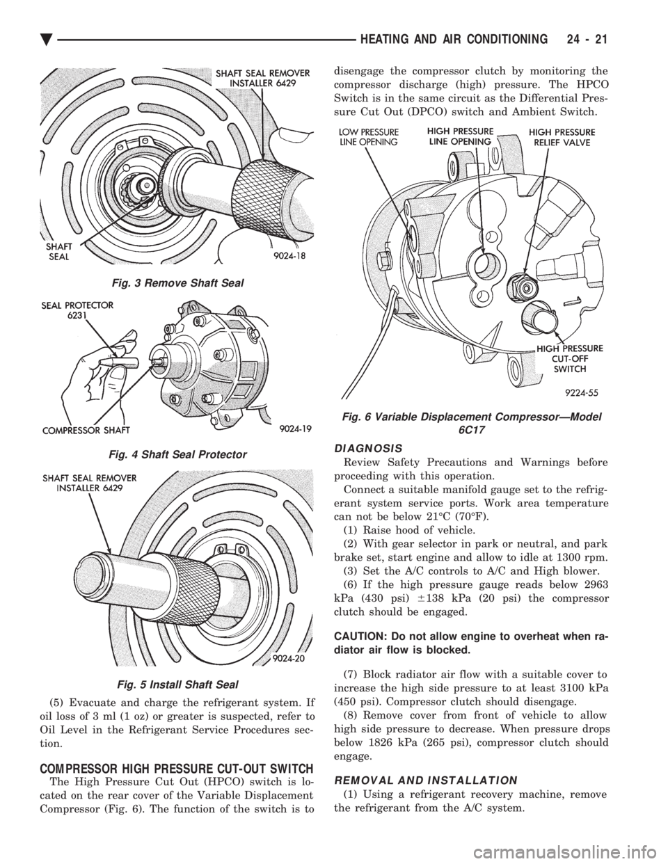
The High Pressure Cut Out (HPCO) switch is lo-
cated on the rear cover of the Variable Displacement
Compressor (Fig. 6). The function of the switch is to disengage the compressor clutch by monitoring the
compressor discharge (high) pressure. The HPCO
Switch is in the same circuit as the Differential Pres-
sure Cut Out (DPCO) switch and Ambient Switch.
DIAGNOSIS
Review Safety Precautions and Warnings before
proceeding with this operation. Connect a suitable manifold gauge set to the refrig-
erant system service ports. Work area temperature
can not be below 21ÉC (70ÉF). (1) Raise hood of vehicle.
(2) With gear selector in park or neutral, and park
brake set, start engine and allow to idle at 1300 rpm. (3) Set the A/C controls to A/C and High blower.
(6) If the high pressure gauge reads below 2963
kPa (430 psi) 6138 kPa (20 psi) the compressor
clutch should be engaged.
CAUTION: Do not allow engine to overheat when ra-
diator air flow is blocked.
(7) Block radiator air flow with a suitable cover to
increase the high side pressure to at least 3100 kPa
(450 psi). Compressor clutch should disengage. (8) Remove cover from front of vehicle to allow
high side pressure to decrease. When pressure drops
below 1826 kPa (265 psi), compressor clutch should
engage.
REMOVAL AND INSTALLATION
(1) Using a refrigerant recovery machine, remove
the refrigerant from the A/C system.
Fig. 3 Remove Shaft Seal
Fig. 4 Shaft Seal Protector
Fig. 5 Install Shaft Seal
Fig. 6 Variable Displacement CompressorÐModel 6C17
Ä HEATING AND AIR CONDITIONING 24 - 21
Page 2351 of 2438
COMPONENT SERVICE PROCEDURES INDEX
page page
Air Distribution Duct ...................... 50
Air Distribution Duct ...................... 52
Ambient Switch .......................... 47
Blend-Air Door .......................... 64
Blower Motor ............................ 58
Blower Motor Wheel Assembly .............. 58
Blower Resistor Block ..................... 49
Condensate Drain Tube ................... 64
Condenser Assembly ...................... 57
Condenser Fan Control Switch .............. 47
Defroster Duct ........................... 51
Defroster Duct Adapter .................... 51
Defroster Ducts/Demister Ducts and Hoses ..... 52
Differential Pressure Cut-Out Switch Diagnosis . . 48
Evaporator Coil .......................... 64 Expansion Valve
......................... 55
Filter-Drier Assembly ...................... 57
Fin-Sensing Cycling Clutch Switch ............ 53
Heater Core ............................ 64
Heater Hoses ........................... 51
Heater-A/C Unit AssemblyÐRemoval and Installation ............................ 61
Heater-A/C Unit Recondition ................ 63
Low or Differential Pressure Cut-Off Switch ..... 54
Temperature Control CableÐAA,AP,AG and AJ Models ............................ 49
Temperature Control CableÐAC/AY Models .... 48
Vacuum ActuatorÐFresh/Recirc Door ......... 50
Vacuum ActuatorsÐMode Doors ............. 52
AMBIENT SWITCH
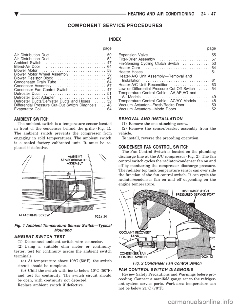
The ambient switch is a temperature sensor located
in front of the condenser behind the grille (Fig. 1).
The ambient switch prevents the compressor from
engaging in cold temperatures. The ambient switch
is a sealed factory calibrated unit. It must be re-
placed if defective.
AMBIENT SWITCH TEST
(1) Disconnect ambient switch wire connector.
(2) Using a suitable ohm meter or continuity
tester, test for continuity across the ambient switch
terminals. (a) At temperature above 10ÉC (50ÉF), the switch
circuit should be complete. (b) Chill the switch with ice to below 10ÉC (50ÉF)
and test for continuity. The switch circuit should
be open, with continuity not detected.
Replace ambient switch if defective.
REMOVAL AND INSTALLATION
(1) Remove the one attaching screw.
(2) Remove the sensor/bracket assembly from the
vehicle. To install, reverse the preceding operation.
CONDENSER FAN CONTROL SWITCH
The Fan Control Switch is located on the plumbing
discharge line at the A/C compressor (Fig. 2). The fan
control switch cycles the radiator/condenser fan on and
off by monitoring the compressor discharge pressure.
The radiator top tank temperature sensor can over ride
the function of the fan control switch. It can cycle the
radiator/condenser fan on and off depending on the
engine temperature.
FAN CONTROL SWITCH DIAGNOSIS
Review Safety Precautions and Warnings before pro-
ceeding. Connect a manifold gauge set to the refriger-
ant system service ports. Work area temperature can
not be below 21ÉC (70ÉF).
Fig. 1 Ambient Temperature Sensor SwitchÐTypical Mounting
Fig. 2 Condenser Fan Control Switch
Ä HEATING AND AIR CONDITIONING 24 - 47