1993 CHEVROLET PLYMOUTH ACCLAIM radiator
[x] Cancel search: radiatorPage 1812 of 2438
tween the flashes representing the first and second
digits of the code. Longer pauses separate individual
trouble codes.(3) Refer to the Diagnostic Trouble Code Charts at
the end of this group.
STATE DISPLAY TEST MODE
The switch inputs to the powertrain control module
(PCM) have two recognized states; HIGH and LOW.
For this reason, the PCM cannot recognize the differ-
ence between a selected switch position versus an
open circuit, a short circuit, or a defective switch. If
the State Display screen shows the change from
HIGH to LOW or LOW to HIGH, assume the entire
switch circuit to the PCM functions properly. From
the state display screen, access either State Display
Inputs and Outputs or State Display Sensors.
STATE DISPLAY INPUTS AND OUTPUTS
Connect the DRBII scan tool to the vehicle and ac-
cess the State Display screen. Then access Inputs and
Outputs. The following is a list of the engine control
system functions accessible through the Inputs and
Outputs screen.
² Park/Neutral Switch (automatic transaxle only)
² Speed Control Resume
² Speed Control On/Off
² Speed Control Set
² Brake Switch
² A/C Switch Sense
² S/C Vent Solenoid
² S/C Vacuum Solenoid
² A/C Clutch Relay
² Auto Shutdown Relay
² Radiator Fan Relay
² (Duty Cycle) EVAP Purge Solenoid
² Malfunction Indicator (Check Engine) Lamp
STATE DISPLAY SENSORS
Connect the DRBII scan tool to the vehicle and ac-
cess the State Display screen. Then access Sensor
Display. The following is a list of the engine control
system functions accessible through the Sensor Dis-
play screen.
² Oxygen Sensor Signal
² Engine Coolant Temperature
² Engine Coolant Temp Sensor
² Throttle Position
² Minimum Throttle
² Battery Voltage
² MAP Sensor Reading
² Idle Air Control Motor Position
² Adaptive Fuel Factor
² Barometric Pressure
² Min Airflow Idle Spd (Speed)
² Engine Speed
² Fault #1 Key-On Info
² Module Spark Advance ²
Speed Control Target
² Fault #2 Key-on Info
² Fault #3 Key-on Info
² Speed Control Status
² Charging System Goal
² Theft Alarm Status
² Battery Temperature
² Flex Fuel (Methanol Concentration) Sensor Volt-
age
² Methanol Content (percentage)
² Map Sensor Voltage
² Vehicle Speed
² Oxygen Sensor State
² MAP Gauge Reading
² Throttle Opening (percentage)
² Total Spark Advance
CIRCUIT ACTUATION TEST MODE
The Circuit Actuation Test Mode checks for proper
operation of output circuits or devices the powertrain
control module (PCM) cannot internally recognize.
The PCM attempts to activate these outputs and al-
low an observer to verify proper operation. Most of
the tests provide an audible or visual indication of
device operation (click of relay contacts, fuel spray,
etc.). Except for intermittent conditions, if a device
functions properly during testing, assume the device,
its associated wiring, and driver circuit work cor-
rectly.
OBTAINING CIRCUIT ACTUATION TEST
Connect the DRBII scan tool to the vehicle and ac-
cess the Actuators screen. The following is a list of
the engine control system functions accessible
through Actuators screens. Subordinate screens for
each actuator test are also listed. Stop All Tests
Ignition Coil No. 1
Fuel Injector No. 1
Fuel Injector No. 2
Fuel Injector No. 3
Fuel Injector No. 4
Idle Air Control Motor Open/Close
Fuel System
Radiator Fan Relay
A/C Clutch Relay
Auto Shutdown Relay
EVAP Purge Solenoid
Speed Control Servo Solenoids
Generator Field
Tachometer Output
Torque Converter Clutch Solenoid
All Solenoids/Relays
Speed Control Vent Solenoid
Speed Control Vacuum Solenoid
ASD Fuel System Test
14 - 72 FUEL SYSTEMS Ä
Page 1823 of 2438
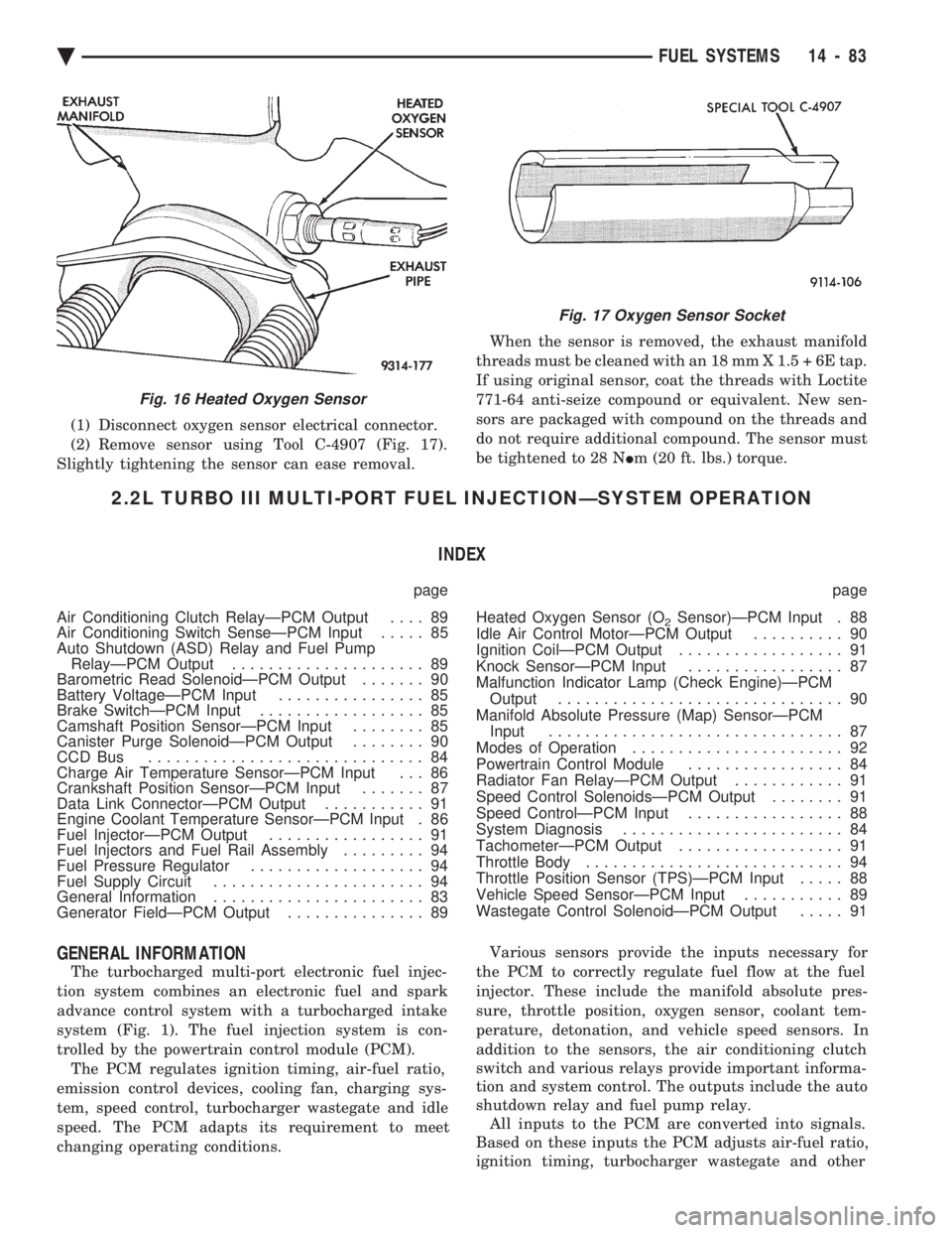
(1) Disconnect oxygen sensor electrical connector.
(2) Remove sensor using Tool C-4907 (Fig. 17).
Slightly tightening the sensor can ease removal. When the sensor is removed, the exhaust manifold
threads must be cleaned with an 18 mm X 1.5 + 6E tap.
If using original sensor, coat the threads with Loctite
771-64 anti-seize compound or equivalent. New sen-
sors are packaged with compound on the threads and
do not require additional compound. The sensor must
be tightened to 28 N Im (20 ft. lbs.) torque.
2.2L TURBO III MULTI-PORT FUEL INJECTIONÐSYSTEM OPERATION
INDEX
page page
Air Conditioning Clutch RelayÐPCM Output .... 89
Air Conditioning Switch SenseÐPCM Input ..... 85
Auto Shutdown (ASD) Relay and Fuel Pump RelayÐPCM Output ..................... 89
Barometric Read SolenoidÐPCM Output ....... 90
Battery VoltageÐPCM Input ................ 85
Brake SwitchÐPCM Input .................. 85
Camshaft Position SensorÐPCM Input ........ 85
Canister Purge SolenoidÐPCM Output ........ 90
CCD Bus .............................. 84
Charge Air Temperature SensorÐPCM Input . . . 86
Crankshaft Position SensorÐPCM Input ....... 87
Data Link ConnectorÐPCM Output ........... 91
Engine Coolant Temperature SensorÐPCM Input . 86
Fuel InjectorÐPCM Output ................. 91
Fuel Injectors and Fuel Rail Assembly ......... 94
Fuel Pressure Regulator ................... 94
Fuel Supply Circuit ....................... 94
General Information ....................... 83
Generator FieldÐPCM Output ............... 89 Heated Oxygen Sensor (O
2Sensor)ÐPCM Input . 88
Idle Air Control MotorÐPCM Output .......... 90
Ignition CoilÐPCM Output .................. 91
Knock SensorÐPCM Input ................. 87
Malfunction Indicator Lamp (Check Engine)ÐPCM Output ............................... 90
Manifold Absolute Pressure (Map) SensorÐPCM Input ................................ 87
Modes of Operation ....................... 92
Powertrain Control Module ................. 84
Radiator Fan RelayÐPCM Output ............ 91
Speed Control SolenoidsÐPCM Output ........ 91
Speed ControlÐPCM Input ................. 88
System Diagnosis ........................ 84
TachometerÐPCM Output .................. 91
Throttle Body ............................ 94
Throttle Position Sensor (TPS)ÐPCM Input ..... 88
Vehicle Speed SensorÐPCM Input ........... 89
Wastegate Control SolenoidÐPCM Output ..... 91
GENERAL INFORMATION
The turbocharged multi-port electronic fuel injec-
tion system combines an electronic fuel and spark
advance control system with a turbocharged intake
system (Fig. 1). The fuel injection system is con-
trolled by the powertrain control module (PCM). The PCM regulates ignition timing, air-fuel ratio,
emission control devices, cooling fan, charging sys-
tem, speed control, turbocharger wastegate and idle
speed. The PCM adapts its requirement to meet
changing operating conditions. Various sensors provide the inputs necessary for
the PCM to correctly regulate fuel flow at the fuel
injector. These include the manifold absolute pres-
sure, throttle position, oxygen sensor, coolant tem-
perature, detonation, and vehicle speed sensors. In
addition to the sensors, the air conditioning clutch
switch and various relays provide important informa-
tion and system control. The outputs include the auto
shutdown relay and fuel pump relay. All inputs to the PCM are converted into signals.
Based on these inputs the PCM adjusts air-fuel ratio,
ignition timing, turbocharger wastegate and other
Fig. 16 Heated Oxygen Sensor
Fig. 17 Oxygen Sensor Socket
Ä FUEL SYSTEMS 14 - 83
Page 1825 of 2438
² Manifold Absolute Pressure (MAP) Sensor
² Oxygen Sensor
² SCI Receive
² Speed Control System Controls
² Throttle Position Sensor
² Vehicle Speed Sensor
PCM Outputs:
² Air Conditioning Clutch Relay
² Generator Field
² Idle Air Control Motor
² Auto Shutdown (ASD) Relay
² Barometric Read Solenoid
² Canister Purge Solenoid
² Malfunction Indicator Lamp (Check Engine Lamp)
² Data Link Connector
² Fuel Injectors
² Ignition Coil
² Radiator Fan Relay
² Speed Control Solenoids
² Tachometer Output
² Wastegate Solenoid
Based on inputs it receives, the PCM adjusts fuel
injector pulse width, idle speed, ignition spark ad-
vance, ignition coil dwell and canister purge opera-
tion. The PCM regulates operation of the cooling fan,
A/C and speed control systems. The PCM changes
generator charge rate by adjusting the generator
field. The PCM adjusts injector pulse width (air-fuel ra-
tio) based on the following inputs.
² battery voltage
² engine coolant temperature
² exhaust gas content
² engine speed (crankshaft position sensor)
² manifold absolute pressure
² throttle position
The PCM adjusts ignition timing based on the fol-
lowing inputs.
² engine coolant temperature
² knock sensor
² engine speed (crankshaft position sensor)
² manifold absolute pressure
² throttle position
The Automatic Shut Down (ASD) and Fuel Pump
relays are mounted externally, but turned on and off
by the PCM through the same circuit. The camshaft position sensor and crankshaft posi-
tion sensor signals are sent to the PCM. If the PCM
does not receive both signals within approximately
one second of engine cranking, it deactivates the
ASD relay and fuel pump relay. When these relays
are deactivated, power is shut off to the fuel injector,
ignition coil, oxygen sensor heating element and fuel
pump. The PCM contains a voltage converter that
changes battery voltage to a regulated 8.0 volts. The
8.0 volts power the camshaft position sensor, crank- shaft position sensor and vehicle speed sensor. The
PCM also provides a 5.0 volts supply for the coolant
temperature sensor, manifold absolute pressure sen-
sor and throttle position sensor.
AIR CONDITIONING SWITCH SENSEÐPCM INPUT
When the air conditioning or defrost switch is put
in the ON position and the low pressure and high
pressure switches are closed, the PCM receives an in-
put for air conditioning. After receiving this input,
the PCM activates the A/C compressor clutch by
grounding the A/C clutch relay. The PCM also ad-
justs idle speed to a scheduled RPM to compensate
for increased engine load.
BATTERY VOLTAGEÐPCM INPUT
The PCM monitors the battery voltage input to de-
termine fuel injector pulse width and generator field
control. If battery voltage is low the PCM will in-
crease injector pulse width (period of time that the
injector is energized).
BRAKE SWITCHÐPCM INPUT
When the brake switch is activated, the PCM re-
ceives an input indicating that the brakes are being
applied. After receiving this input, the PCM vents
the speed control servo. Venting the servo turns the
speed control system off. The brake switch is
mounted on the brake pedal support bracket.
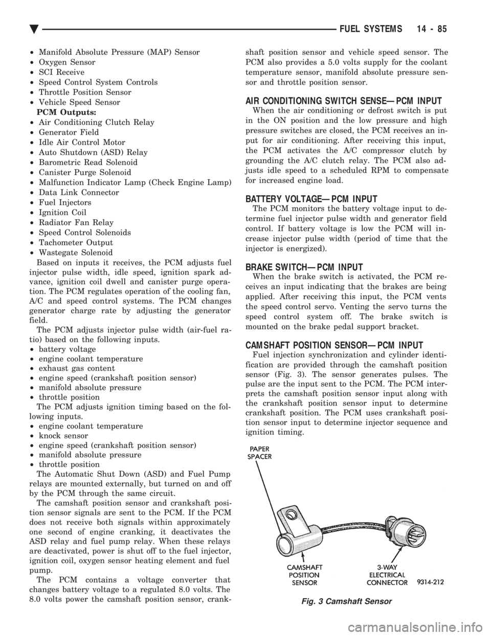
CAMSHAFT POSITION SENSORÐPCM INPUT
Fuel injection synchronization and cylinder identi-
fication are provided through the camshaft position
sensor (Fig. 3). The sensor generates pulses. The
pulse are the input sent to the PCM. The PCM inter-
prets the camshaft position sensor input along with
the crankshaft position sensor input to determine
crankshaft position. The PCM uses crankshaft posi-
tion sensor input to determine injector sequence and
ignition timing.
Fig. 3 Camshaft Sensor
Ä FUEL SYSTEMS 14 - 85
Page 1829 of 2438
resenting throttle blade position. As the position of
the throttle blade changes, the resistance of the TPS
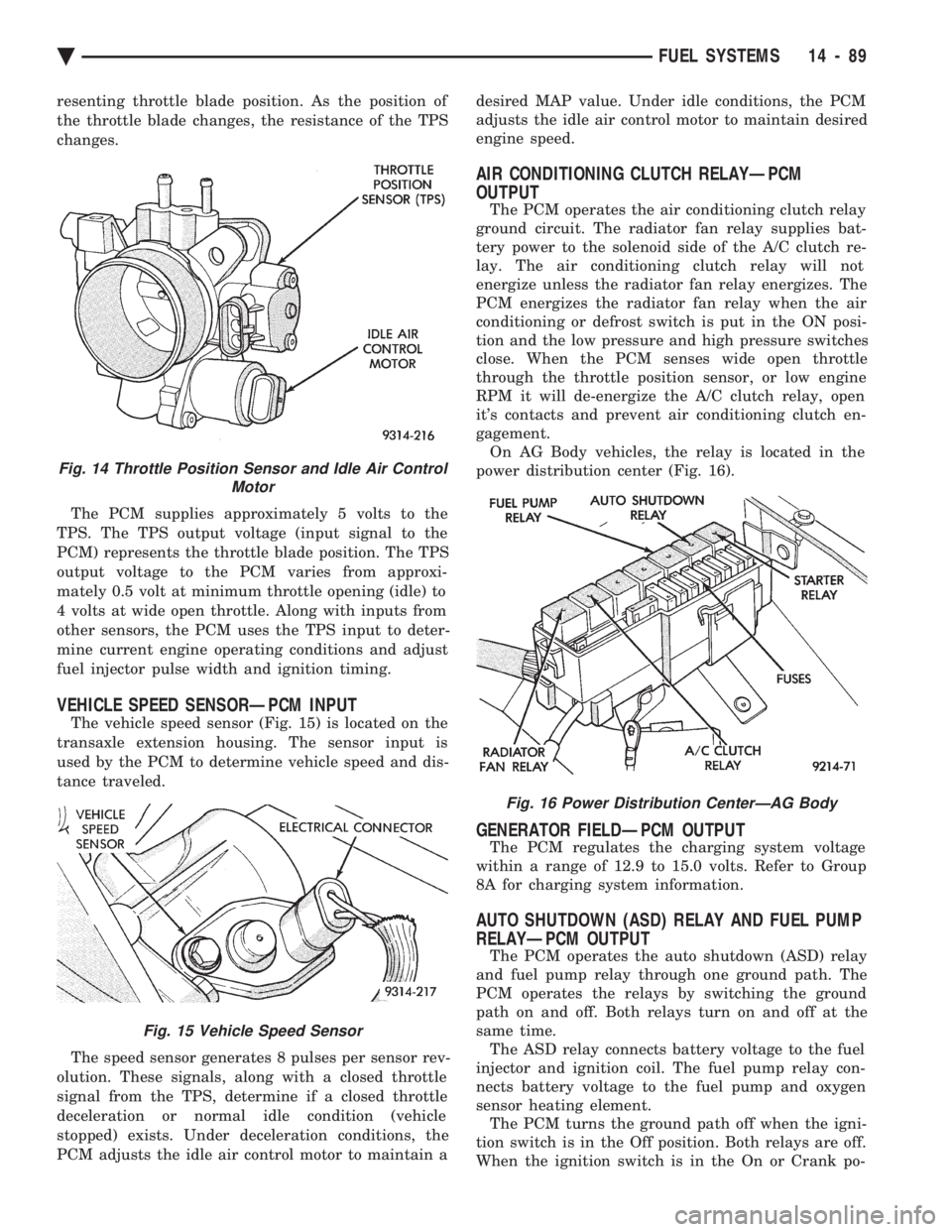
changes. The PCM supplies approximately 5 volts to the
TPS. The TPS output voltage (input signal to the
PCM) represents the throttle blade position. The TPS
output voltage to the PCM varies from approxi-
mately 0.5 volt at minimum throttle opening (idle) to
4 volts at wide open throttle. Along with inputs from
other sensors, the PCM uses the TPS input to deter-
mine current engine operating conditions and adjust
fuel injector pulse width and ignition timing.
VEHICLE SPEED SENSORÐPCM INPUT
The vehicle speed sensor (Fig. 15) is located on the
transaxle extension housing. The sensor input is
used by the PCM to determine vehicle speed and dis-
tance traveled.
The speed sensor generates 8 pulses per sensor rev-
olution. These signals, along with a closed throttle
signal from the TPS, determine if a closed throttle
deceleration or normal idle condition (vehicle
stopped) exists. Under deceleration conditions, the
PCM adjusts the idle air control motor to maintain a desired MAP value. Under idle conditions, the PCM
adjusts the idle air control motor to maintain desired
engine speed.
AIR CONDITIONING CLUTCH RELAYÐPCM
OUTPUT
The PCM operates the air conditioning clutch relay
ground circuit. The radiator fan relay supplies bat-
tery power to the solenoid side of the A/C clutch re-
lay. The air conditioning clutch relay will not
energize unless the radiator fan relay energizes. The
PCM energizes the radiator fan relay when the air
conditioning or defrost switch is put in the ON posi-
tion and the low pressure and high pressure switches
close. When the PCM senses wide open throttle
through the throttle position sensor, or low engine
RPM it will de-energize the A/C clutch relay, open
it's contacts and prevent air conditioning clutch en-
gagement. On AG Body vehicles, the relay is located in the
power distribution center (Fig. 16).
GENERATOR FIELDÐPCM OUTPUT
The PCM regulates the charging system voltage
within a range of 12.9 to 15.0 volts. Refer to Group
8A for charging system information.
AUTO SHUTDOWN (ASD) RELAY AND FUEL PUMP
RELAYÐPCM OUTPUT
The PCM operates the auto shutdown (ASD) relay
and fuel pump relay through one ground path. The
PCM operates the relays by switching the ground
path on and off. Both relays turn on and off at the
same time. The ASD relay connects battery voltage to the fuel
injector and ignition coil. The fuel pump relay con-
nects battery voltage to the fuel pump and oxygen
sensor heating element. The PCM turns the ground path off when the igni-
tion switch is in the Off position. Both relays are off.
When the ignition switch is in the On or Crank po-
Fig. 14 Throttle Position Sensor and Idle Air Control Motor
Fig. 15 Vehicle Speed Sensor
Fig. 16 Power Distribution CenterÐAG Body
Ä FUEL SYSTEMS 14 - 89
Page 1831 of 2438
diagnostic trouble codes stored in the PCM will be
displayed. Refer to the 2.2L Turbo III Multi-port Fuel
InjectionÐOn-Board Diagnostics section of this
Group for Diagnostic trouble code Descriptions.
DATA LINK CONNECTORÐPCM OUTPUT
The data link connector provides the technician
with the means to connect the DRBII scan tool to di-
agnosis the vehicle.
FUEL INJECTORÐPCM OUTPUT
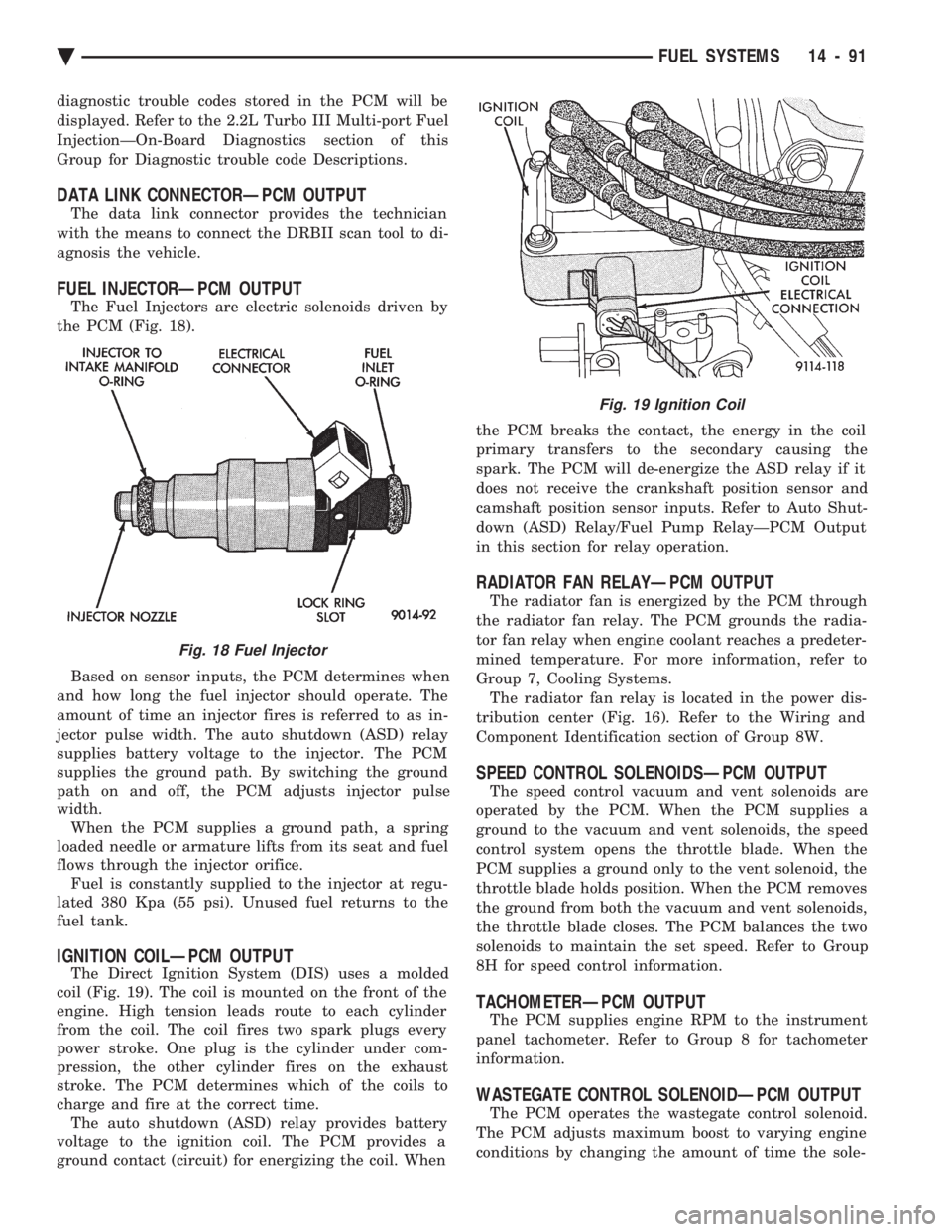
The Fuel Injectors are electric solenoids driven by
the PCM (Fig. 18).
Based on sensor inputs, the PCM determines when
and how long the fuel injector should operate. The
amount of time an injector fires is referred to as in-
jector pulse width. The auto shutdown (ASD) relay
supplies battery voltage to the injector. The PCM
supplies the ground path. By switching the ground
path on and off, the PCM adjusts injector pulse
width. When the PCM supplies a ground path, a spring
loaded needle or armature lifts from its seat and fuel
flows through the injector orifice. Fuel is constantly supplied to the injector at regu-
lated 380 Kpa (55 psi). Unused fuel returns to the
fuel tank.
IGNITION COILÐPCM OUTPUT
The Direct Ignition System (DIS) uses a molded
coil (Fig. 19). The coil is mounted on the front of the
engine. High tension leads route to each cylinder
from the coil. The coil fires two spark plugs every
power stroke. One plug is the cylinder under com-
pression, the other cylinder fires on the exhaust
stroke. The PCM determines which of the coils to
charge and fire at the correct time. The auto shutdown (ASD) relay provides battery
voltage to the ignition coil. The PCM provides a
ground contact (circuit) for energizing the coil. When the PCM breaks the contact, the energy in the coil
primary transfers to the secondary causing the
spark. The PCM will de-energize the ASD relay if it
does not receive the crankshaft position sensor and
camshaft position sensor inputs. Refer to Auto Shut-
down (ASD) Relay/Fuel Pump RelayÐPCM Output
in this section for relay operation.
RADIATOR FAN RELAYÐPCM OUTPUT
The radiator fan is energized by the PCM through
the radiator fan relay. The PCM grounds the radia-
tor fan relay when engine coolant reaches a predeter-
mined temperature. For more information, refer to
Group 7, Cooling Systems. The radiator fan relay is located in the power dis-
tribution center (Fig. 16). Refer to the Wiring and
Component Identification section of Group 8W.
SPEED CONTROL SOLENOIDSÐPCM OUTPUT
The speed control vacuum and vent solenoids are
operated by the PCM. When the PCM supplies a
ground to the vacuum and vent solenoids, the speed
control system opens the throttle blade. When the
PCM supplies a ground only to the vent solenoid, the
throttle blade holds position. When the PCM removes
the ground from both the vacuum and vent solenoids,
the throttle blade closes. The PCM balances the two
solenoids to maintain the set speed. Refer to Group
8H for speed control information.
TACHOMETERÐPCM OUTPUT
The PCM supplies engine RPM to the instrument
panel tachometer. Refer to Group 8 for tachometer
information.
WASTEGATE CONTROL SOLENOIDÐPCM OUTPUT
The PCM operates the wastegate control solenoid.
The PCM adjusts maximum boost to varying engine
conditions by changing the amount of time the sole-
Fig. 18 Fuel Injector
Fig. 19 Ignition Coil
Ä FUEL SYSTEMS 14 - 91
Page 1836 of 2438
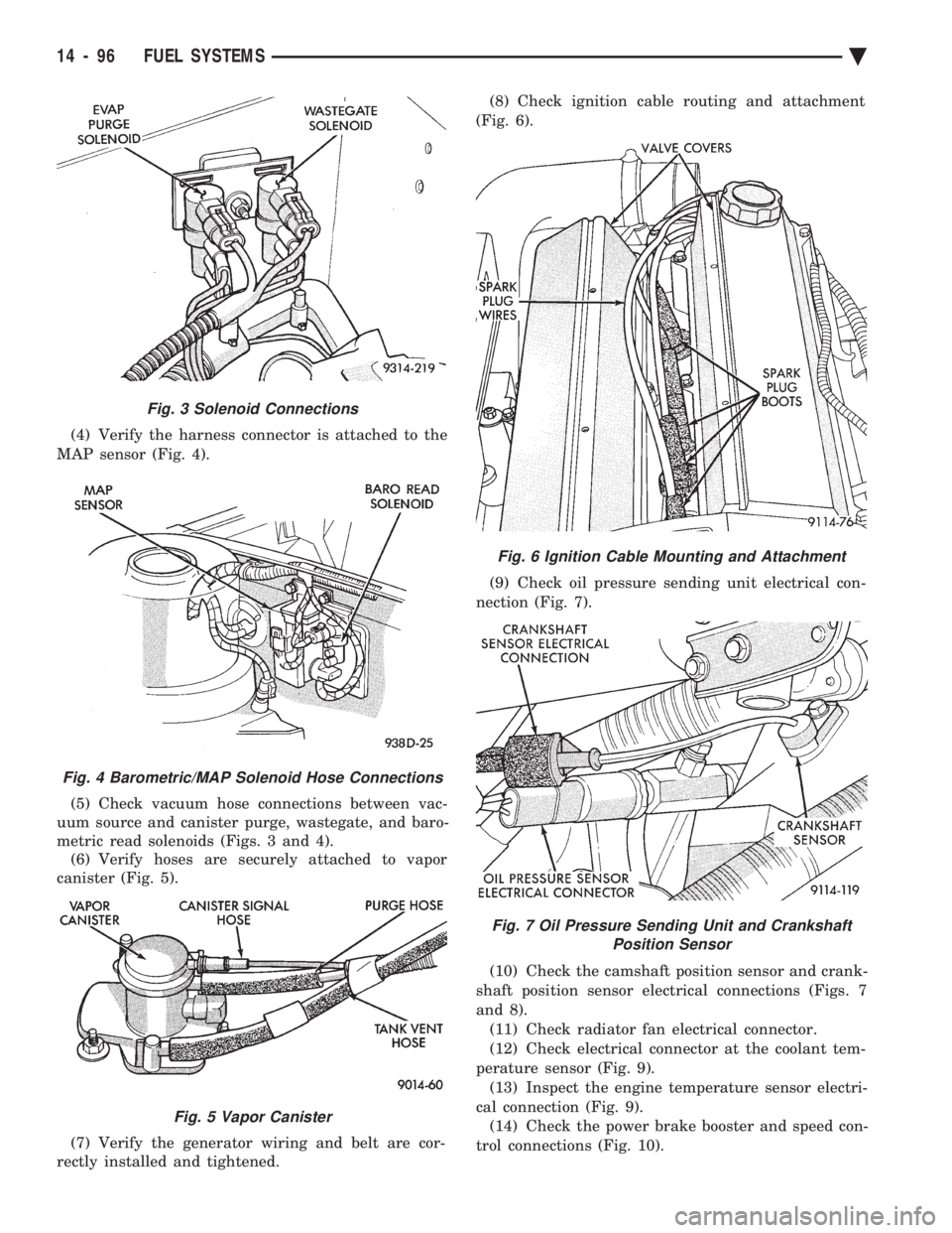
(4) Verify the harness connector is attached to the
MAP sensor (Fig. 4).
(5) Check vacuum hose connections between vac-
uum source and canister purge, wastegate, and baro-
metric read solenoids (Figs. 3 and 4). (6) Verify hoses are securely attached to vapor
canister (Fig. 5).
(7) Verify the generator wiring and belt are cor-
rectly installed and tightened. (8) Check ignition cable routing and attachment
(Fig. 6).
(9) Check oil pressure sending unit electrical con-
nection (Fig. 7).
(10) Check the camshaft position sensor and crank-
shaft position sensor electrical connections (Figs. 7
and 8). (11) Check radiator fan electrical connector.
(12) Check electrical connector at the coolant tem-
perature sensor (Fig. 9). (13) Inspect the engine temperature sensor electri-
cal connection (Fig. 9). (14) Check the power brake booster and speed con-
trol connections (Fig. 10).
Fig. 6 Ignition Cable Mounting and Attachment
Fig. 7 Oil Pressure Sending Unit and Crankshaft Position Sensor
Fig. 3 Solenoid Connections
Fig. 4 Barometric/MAP Solenoid Hose Connections
Fig. 5 Vapor Canister
14 - 96 FUEL SYSTEMS Ä
Page 1844 of 2438
SYSTEM TESTS
Apply parking brake and/or block wheels be-
fore performing idle check or adjustment, or any
engine running tests.
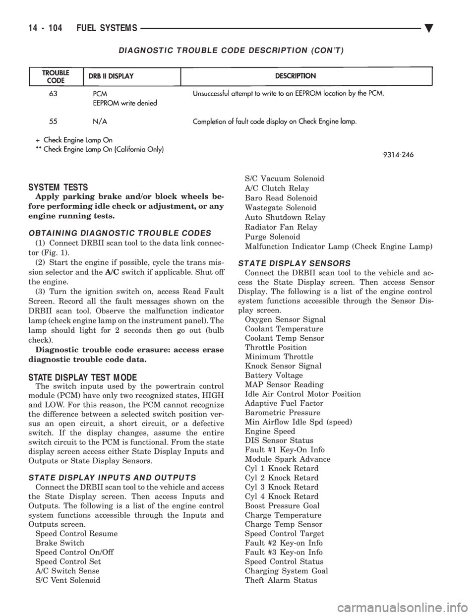
OBTAINING DIAGNOSTIC TROUBLE CODES
(1) Connect DRBII scan tool to the data link connec-
tor (Fig. 1). (2) Start the engine if possible, cycle the trans mis-
sion selector and the A/Cswitch if applicable. Shut off
the engine. (3) Turn the ignition switch on, access Read Fault
Screen. Record all the fault messages shown on the
DRBII scan tool. Observe the malfunction indicator
lamp (check engine lamp on the instrument panel). The
lamp should light for 2 seconds then go out (bulb
check). Diagnostic trouble code erasure: access erase
diagnostic trouble code data.
STATE DISPLAY TEST MODE
The switch inputs used by the powertrain control
module (PCM) have only two recognized states, HIGH
and LOW. For this reason, the PCM cannot recognize
the difference between a selected switch position ver-
sus an open circuit, a short circuit, or a defective
switch. If the display changes, assume the entire
switch circuit to the PCM is functional. From the state
display screen access either State Display Inputs and
Outputs or State Display Sensors.
STATE DISPLAY INPUTS AND OUTPUTS
Connect the DRBII scan tool to the vehicle and access
the State Display screen. Then access Inputs and
Outputs. The following is a list of the engine control
system functions accessible through the Inputs and
Outputs screen. Speed Control Resume
Brake Switch
Speed Control On/Off
Speed Control Set
A/C Switch Sense
S/C Vent Solenoid S/C Vacuum Solenoid
A/C Clutch Relay
Baro Read Solenoid
Wastegate Solenoid
Auto Shutdown Relay
Radiator Fan Relay
Purge Solenoid
Malfunction Indicator Lamp (Check Engine Lamp)
STATE DISPLAY SENSORS
Connect the DRBII scan tool to the vehicle and ac-
cess the State Display screen. Then access Sensor
Display. The following is a list of the engine control
system functions accessible through the Sensor Dis-
play screen. Oxygen Sensor Signal
Coolant Temperature
Coolant Temp Sensor
Throttle Position
Minimum Throttle
Knock Sensor Signal
Battery Voltage
MAP Sensor Reading
Idle Air Control Motor Position
Adaptive Fuel Factor
Barometric Pressure
Min Airflow Idle Spd (speed)
Engine Speed
DIS Sensor Status
Fault #1 Key-On Info
Module Spark Advance
Cyl 1 Knock Retard
Cyl 2 Knock Retard
Cyl 3 Knock Retard
Cyl 4 Knock Retard
Boost Pressure Goal
Charge Temperature
Charge Temp Sensor
Speed Control Target
Fault #2 Key-on Info
Fault #3 Key-on Info
Speed Control Status
Charging System Goal
Theft Alarm Status
DIAGNOSTIC TROUBLE CODE DESCRIPTION (CON'T)
14 - 104 FUEL SYSTEMS Ä
Page 1845 of 2438
Wastegate Duty Cycle
Battery Temperature
Map Sensor Voltage
Vehicle Speed
Oxygen Sensor State
Baro Read Update
MAP Gauge Reading
Throttle Opening (percentage)
Total Spark Advance
CIRCUIT ACTUATION TEST MODE
The purpose of the circuit actuation test mode is to
check for the proper operation of output circuits or
devices which the powertrain control module (PCM)
cannot internally recognize. The PCM can attempt to
activate these outputs and allow an observer to ver-
ify proper operation. Most of the tests available in
this mode provide an audible or visual indication of
device operation (click of relay contacts, spray fuel,
etc.). With the exception of an intermittent condition,
if a device functions properly during its test, assume
the device, its associated wiring, and its driver cir-
cuit are in working order.
OBTAINING CIRCUIT ACTUATION TEST
Connect the DRBII scan tool to the vehicle and ac-
cess the Actuators screen. The following is a list of
the engine control system functions accessible
through Actuators screens. Stop All Tests
Ignition Coil #1
Ignition Coil #2
Fuel Injector #1
Fuel Injector #2
Fuel Injector #3
Idle Air Control Motor Open/Close
Radiator Fan Relay
A/C Clutch Relay
Auto Shutdown Relay
Purge Solenoid
S/C Serv Solenoids
Generator Field
Tachometer Output
Wastegate Solenoid
Baro Read Solenoid
All Solenoids/Relays
Speed Control Vent Solenoid
Speed Control Vacuum Solenoid
ASD Fuel System Test
Fuel Injector #4
THROTTLE BODY MINIMUM AIR FLOW CHECK
PROCEDURE
(1) Warm the engine in neutral until the cooling
fan has cycled on and off at least once. (2) Shut off engine.
(3) Hook-up Tachometer.
(4) Disconnect the PCV valve hose from the nipple
on the intake manifold. (5) Attach air metering fitting, special tool 6457
(0.125 inch orifice), to the intake manifold PCV nip-
ple. (6) Disconnect 3/16 inch manifold vacuum purge
line from the top of the throttle body. Cap the 3/16
inch throttle body nipple. (7) Connect DRBII scan tool.
(8) Restart engine. Allow engine to idle for at least
one minute. (9) Using the DRBII scan tool, access Min. Airflow
Idle Spd. The following will then occur:
² Idle air control motor will fully close.
² Idle spark advance will become fixed.
² Engine RPM will be displayed on the DRBII scan
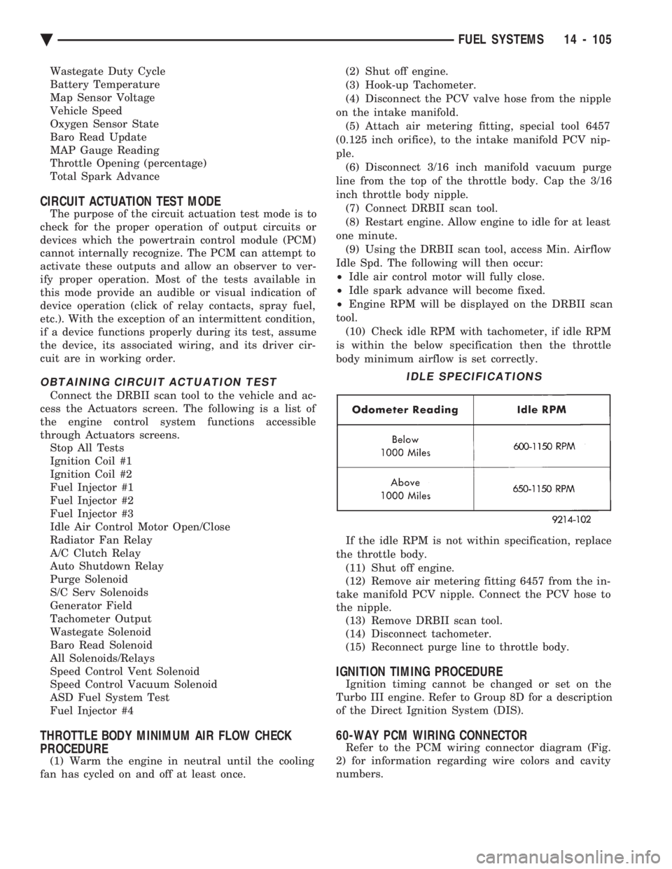
tool. (10) Check idle RPM with tachometer, if idle RPM
is within the below specification then the throttle
body minimum airflow is set correctly.
If the idle RPM is not within specification, replace
the throttle body. (11) Shut off engine.
(12) Remove air metering fitting 6457 from the in-
take manifold PCV nipple. Connect the PCV hose to
the nipple. (13) Remove DRBII scan tool.
(14) Disconnect tachometer.
(15) Reconnect purge line to throttle body.
IGNITION TIMING PROCEDURE
Ignition timing cannot be changed or set on the
Turbo III engine. Refer to Group 8D for a description
of the Direct Ignition System (DIS).
60-WAY PCM WIRING CONNECTOR
Refer to the PCM wiring connector diagram (Fig.
2) for information regarding wire colors and cavity
numbers.
IDLE SPECIFICATIONS
Ä FUEL SYSTEMS 14 - 105