1993 CHEVROLET PLYMOUTH ACCLAIM check engine
[x] Cancel search: check enginePage 1635 of 2438
LEFT SIDE MOUNT
(1) Raise vehicle on hoist and remove left front
wheel. (2) Remove inter splash shield.
(3) Support the transmission with a transmission
jack. (4) Remove the insulator thru bolt from the mount.
(5) Remove the transmission mount fasteners and
remove mount. (6) Reverse removal procedure for installation. En-
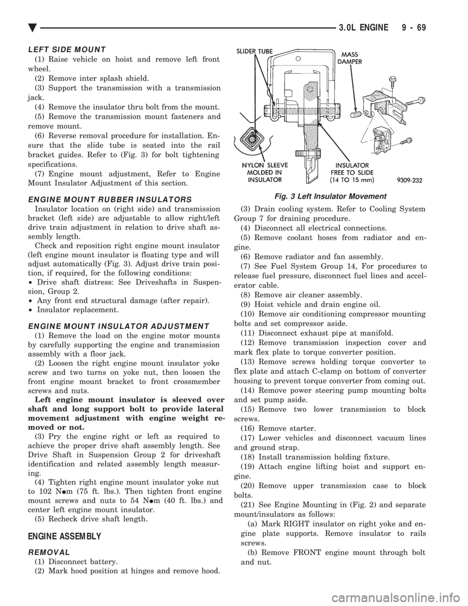
sure that the slide tube is seated into the rail
bracket guides. Refer to (Fig. 3) for bolt tightening
specifications. (7) Engine mount adjustment, Refer to Engine
Mount Insulator Adjustment of this section.
ENGINE MOUNT RUBBER INSULATORS
Insulator location on (right side) and transmission
bracket (left side) are adjustable to allow right/left
drive train adjustment in relation to drive shaft as-
sembly length. Check and reposition right engine mount insulator
(left engine mount insulator is floating type and will
adjust automatically (Fig. 3). Adjust drive train posi-
tion, if required, for the following conditions:
² Drive shaft distress: See Driveshafts in Suspen-
sion, Group 2.
² Any front end structural damage (after repair).
² Insulator replacement.
ENGINE MOUNT INSULATOR ADJUSTMENT
(1) Remove the load on the engine motor mounts
by carefully supporting the engine and transmission
assembly with a floor jack. (2) Loosen the right engine mount insulator yoke
screw and two turns on yoke nut, then loosen the
front engine mount bracket to front crossmember
screws and nuts. Left engine mount insulator is sleeved over
shaft and long support bolt to provide lateral
movement adjustment with engine weight re-
moved or not. (3) Pry the engine right or left as required to
achieve the proper drive shaft assembly length. See
Drive Shaft in Suspension Group 2 for driveshaft
identification and related assembly length measur-
ing. (4) Tighten right engine mount insulator yoke nut
to 102 N Im (75 ft. lbs.). Then tighten front engine
mount screws and nuts to 54 N Im (40 ft. lbs.) and
center left engine mount insulator. (5) Recheck drive shaft length.
ENGINE ASSEMBLY
REMOVAL
(1) Disconnect battery.
(2) Mark hood position at hinges and remove hood. (3) Drain cooling system. Refer to Cooling System
Group 7 for draining procedure. (4) Disconnect all electrical connections.
(5) Remove coolant hoses from radiator and en-
gine. (6) Remove radiator and fan assembly.
(7) See Fuel System Group 14, For procedures to
release fuel pressure, disconnect fuel lines and accel-
erator cable. (8) Remove air cleaner assembly.
(9) Hoist vehicle and drain engine oil.
(10) Remove air conditioning compressor mounting
bolts and set compressor aside. (11) Disconnect exhaust pipe at manifold.
(12) Remove transmission inspection cover and
mark flex plate to torque converter position. (13) Remove screws holding torque converter to
flex plate and attach C-clamp on bottom of converter
housing to prevent torque converter from coming out. (14) Remove power steering pump mounting bolts
and set pump aside. (15) Remove two lower transmission to block
screws. (16) Remove starter.
(17) Lower vehicles and disconnect vacuum lines
and ground strap. (18) Install transmission holding fixture.
(19) Attach engine lifting hoist and support en-
gine. (20) Remove upper transmission case to block
bolts. (21) See Engine Mounting in (Fig. 2) and separate
mount/insulators as follows: (a) Mark RIGHT insulator on right yoke and en-
gine plate supports. Remove insulator to rails
screws. (b) Remove FRONT engine mount through bolt
and nut.
Fig. 3 Left Insulator Movement
Ä 3.0L ENGINE 9 - 69
Page 1640 of 2438
INSTALLATION
(1) Place camshaft sprocket on camshaft.
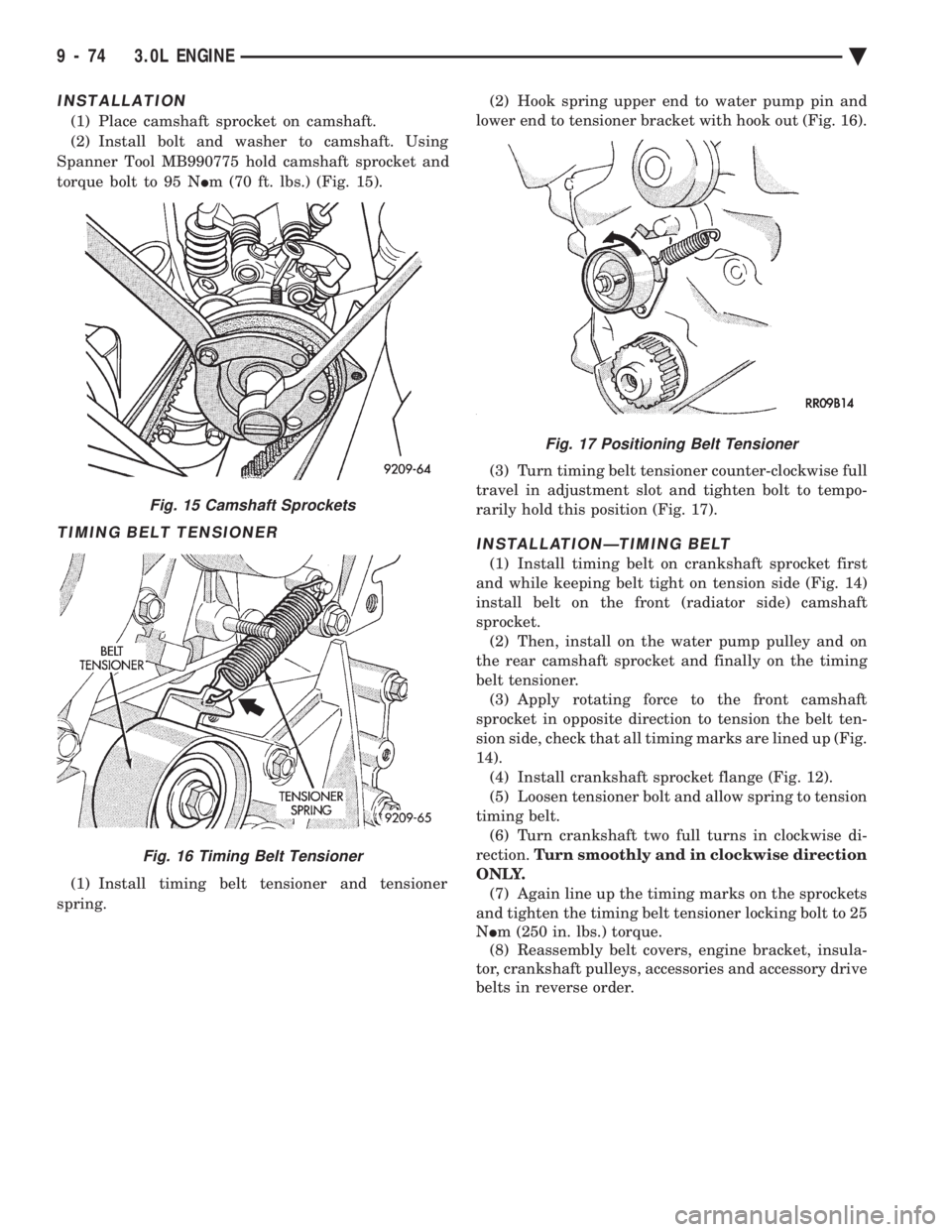
(2) Install bolt and washer to camshaft. Using
Spanner Tool MB990775 hold camshaft sprocket and
torque bolt to 95 N Im (70 ft. lbs.) (Fig. 15).
TIMING BELT TENSIONER
(1) Install timing belt tensioner and tensioner
spring. (2) Hook spring upper end to water pump pin and
lower end to tensioner bracket with hook out (Fig. 16).
(3) Turn timing belt tensioner counter-clockwise full
travel in adjustment slot and tighten bolt to tempo-
rarily hold this position (Fig. 17).
INSTALLATIONÐTIMING BELT
(1) Install timing belt on crankshaft sprocket first
and while keeping belt tight on tension side (Fig. 14)
install belt on the front (radiator side) camshaft
sprocket. (2) Then, install on the water pump pulley and on
the rear camshaft sprocket and finally on the timing
belt tensioner. (3) Apply rotating force to the front camshaft
sprocket in opposite direction to tension the belt ten-
sion side, check that all timing marks are lined up (Fig.
14). (4) Install crankshaft sprocket flange (Fig. 12).
(5) Loosen tensioner bolt and allow spring to tension
timing belt. (6) Turn crankshaft two full turns in clockwise di-
rection. Turn smoothly and in clockwise direction
ONLY. (7) Again line up the timing marks on the sprockets
and tighten the timing belt tensioner locking bolt to 25
N Im (250 in. lbs.) torque.
(8) Reassembly belt covers, engine bracket, insula-
tor, crankshaft pulleys, accessories and accessory drive
belts in reverse order.
Fig. 15 Camshaft Sprockets
Fig. 16 Timing Belt Tensioner
Fig. 17 Positioning Belt Tensioner
9 - 74 3.0L ENGINE Ä
Page 1641 of 2438
CYLINDER HEAD AND CAMSHAFT SERVICE
CYLINDER HEAD COVER REMOVE
(1) Remove air cleaner assembly.
(2) Disconnect battery and relocate spark plug
wires. (3) Remove vacuum connections.
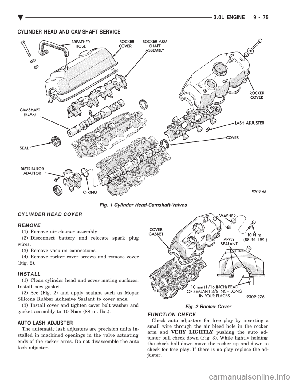
(4) Remove rocker cover screws and remove cover
(Fig. 2).
INSTALL
(1) Clean cylinder head and cover mating surfaces.
Install new gasket. (2) See (Fig. 2) and apply sealant such as Mopar
Silicone Rubber Adhesive Sealant to cover ends. (3) Install cover and tighten cover bolt washer and
gasket assembly to 10 N Im (88 in. lbs.).
AUTO LASH ADJUSTER
The automatic lash adjusters are precision units in-
stalled in machined openings in the valve actuating
ends of the rocker arms. Do not disassemble the auto
lash adjuster.
FUNCTION CHECK
Check auto adjusters for free play by inserting a
small wire through the air bleed hole in the rocker
arm and VERY LIGHTLY pushing the auto ad-
juster ball check down (Fig. 3). While lightly holding
the check ball down move the rocker up and down to
check for free play. If there is no play replace the ad-
juster.
Fig. 1 Cylinder Head-Camshaft-Valves
Fig. 2 Rocker Cover
Ä 3.0L ENGINE 9 - 75
Page 1642 of 2438
CAMSHAFT SERVICE
SEE AUTO LASH ADJUSTER FUNCTION CHECK BEFORE DISASSEMBLY
REMOVAL
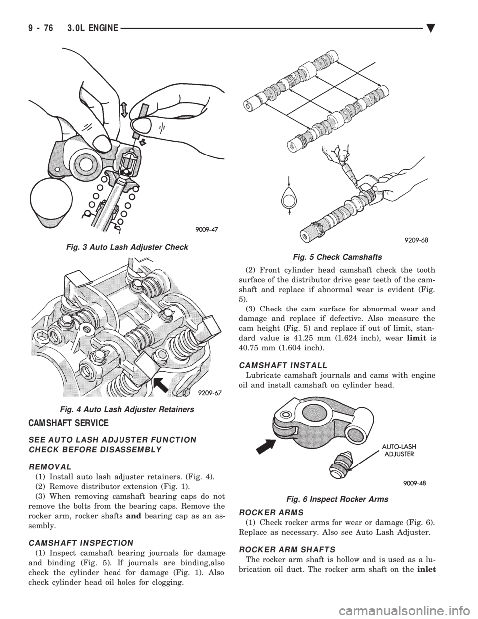
(1) Install auto lash adjuster retainers. (Fig. 4).
(2) Remove distributor extension (Fig. 1).
(3) When removing camshaft bearing caps do not
remove the bolts from the bearing caps. Remove the
rocker arm, rocker shafts andbearing cap as an as-
sembly.
CAMSHAFT INSPECTION
(1) Inspect camshaft bearing journals for damage
and binding (Fig. 5). If journals are binding,also
check the cylinder head for damage (Fig. 1). Also
check cylinder head oil holes for clogging. (2) Front cylinder head camshaft check the tooth
surface of the distributor drive gear teeth of the cam-
shaft and replace if abnormal wear is evident (Fig.
5). (3) Check the cam surface for abnormal wear and
damage and replace if defective. Also measure the
cam height (Fig. 5) and replace if out of limit, stan-
dard value is 41.25 mm (1.624 inch), wear limitis
40.75 mm (1.604 inch).
CAMSHAFT INSTALL
Lubricate camshaft journals and cams with engine
oil and install camshaft on cylinder head.
ROCKER ARMS
(1) Check rocker arms for wear or damage (Fig. 6).
Replace as necessary. Also see Auto Lash Adjuster.
ROCKER ARM SHAFTS
The rocker arm shaft is hollow and is used as a lu-
brication oil duct. The rocker arm shaft on the inlet
Fig. 3 Auto Lash Adjuster Check
Fig. 4 Auto Lash Adjuster Retainers
Fig. 5 Check Camshafts
Fig. 6 Inspect Rocker Arms
9 - 76 3.0L ENGINE Ä
Page 1643 of 2438
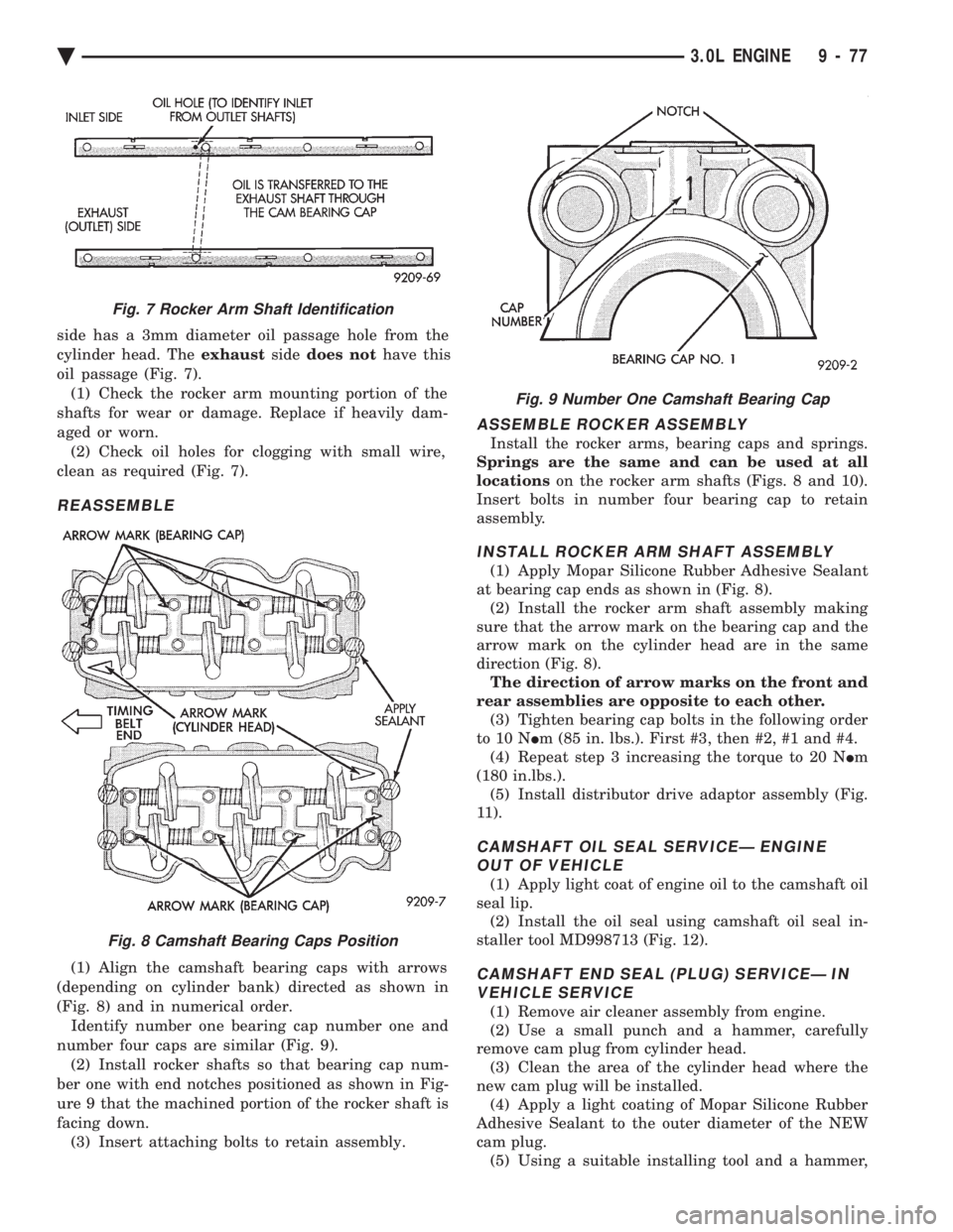
side has a 3mm diameter oil passage hole from the
cylinder head. The exhaustsidedoes not have this
oil passage (Fig. 7). (1) Check the rocker arm mounting portion of the
shafts for wear or damage. Replace if heavily dam-
aged or worn. (2) Check oil holes for clogging with small wire,
clean as required (Fig. 7).
REASSEMBLE
(1) Align the camshaft bearing caps with arrows
(depending on cylinder bank) directed as shown in
(Fig. 8) and in numerical order. Identify number one bearing cap number one and
number four caps are similar (Fig. 9). (2) Install rocker shafts so that bearing cap num-
ber one with end notches positioned as shown in Fig-
ure 9 that the machined portion of the rocker shaft is
facing down. (3) Insert attaching bolts to retain assembly.
ASSEMBLE ROCKER ASSEMBLY
Install the rocker arms, bearing caps and springs.
Springs are the same and can be used at all
locations on the rocker arm shafts (Figs. 8 and 10).
Insert bolts in number four bearing cap to retain
assembly.
INSTALL ROCKER ARM SHAFT ASSEMBLY
(1) Apply Mopar Silicone Rubber Adhesive Sealant
at bearing cap ends as shown in (Fig. 8). (2) Install the rocker arm shaft assembly making
sure that the arrow mark on the bearing cap and the
arrow mark on the cylinder head are in the same
direction (Fig. 8). The direction of arrow marks on the front and
rear assemblies are opposite to each other. (3) Tighten bearing cap bolts in the following order
to 10 N Im (85 in. lbs.). First #3, then #2, #1 and #4.
(4) Repeat step 3 increasing the torque to 20 N Im
(180 in.lbs.). (5) Install distributor drive adaptor assembly (Fig.
11).
CAMSHAFT OIL SEAL SERVICEÐ ENGINE OUT OF VEHICLE
(1) Apply light coat of engine oil to the camshaft oil
seal lip. (2) Install the oil seal using camshaft oil seal in-
staller tool MD998713 (Fig. 12).
CAMSHAFT END SEAL (PLUG) SERVICEÐ IN VEHICLE SERVICE
(1) Remove air cleaner assembly from engine.
(2) Use a small punch and a hammer, carefully
remove cam plug from cylinder head. (3) Clean the area of the cylinder head where the
new cam plug will be installed. (4) Apply a light coating of Mopar Silicone Rubber
Adhesive Sealant to the outer diameter of the NEW
cam plug. (5) Using a suitable installing tool and a hammer,
Fig. 7 Rocker Arm Shaft Identification
Fig. 8 Camshaft Bearing Caps Position
Fig. 9 Number One Camshaft Bearing Cap
Ä 3.0L ENGINE 9 - 77
Page 1645 of 2438
(2) See Camshaft Rocker Arms Removal.
(3) Remove upper intake manifold assembly. Refer
to Intake and Exhaust Manifolds, Group 11. (4) Remove distributor.
(5) Remove exhaust manifolds and cross over Refer
to Intake and Exhaust Manifolds, Group 11.
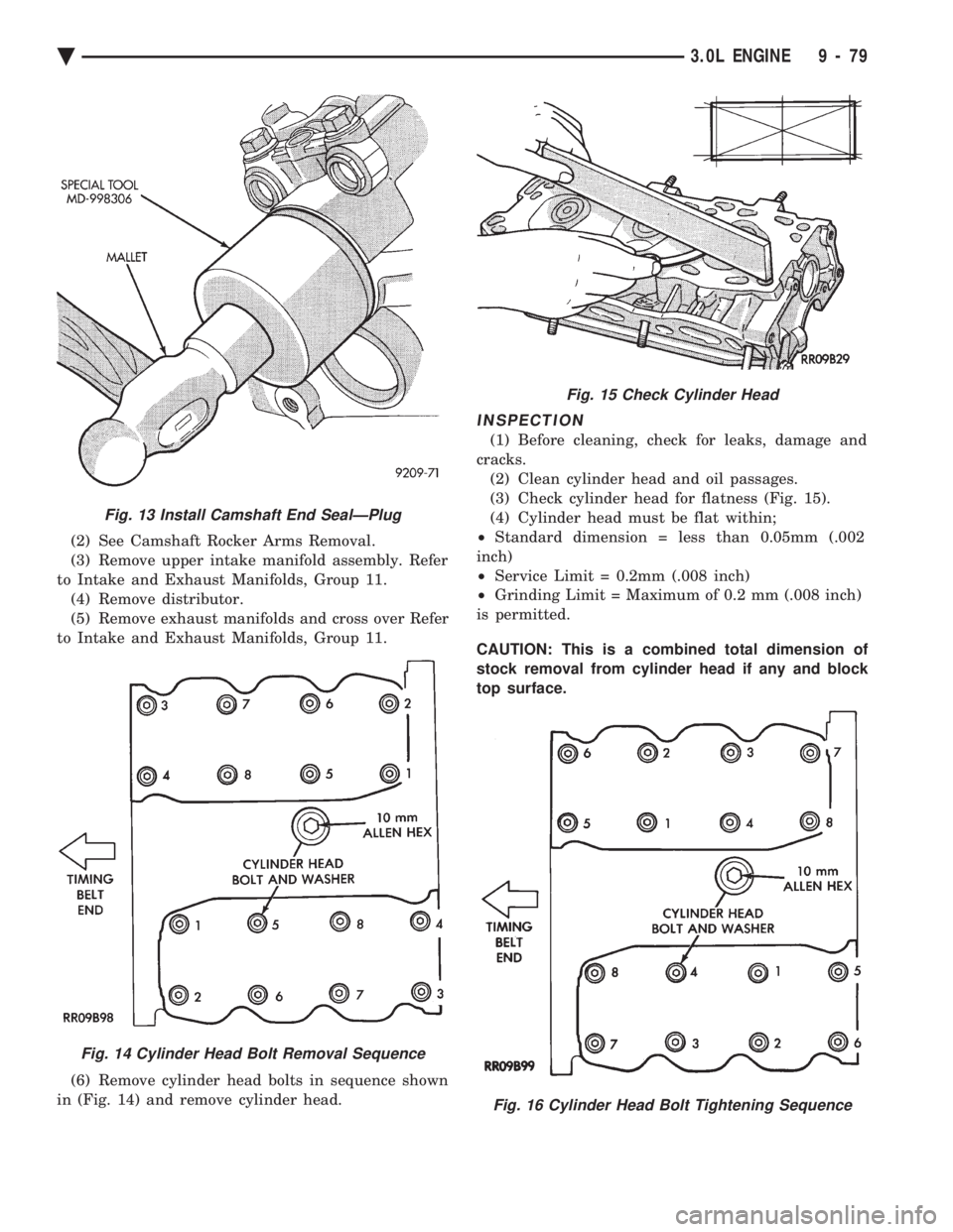
(6) Remove cylinder head bolts in sequence shown
in (Fig. 14) and remove cylinder head.
INSPECTION
(1) Before cleaning, check for leaks, damage and
cracks. (2) Clean cylinder head and oil passages.
(3) Check cylinder head for flatness (Fig. 15).
(4) Cylinder head must be flat within;
² Standard dimension = less than 0.05mm (.002
inch)
² Service Limit = 0.2mm (.008 inch)
² Grinding Limit = Maximum of 0.2 mm (.008 inch)
is permitted.
CAUTION: This is a combined total dimension of
stock removal from cylinder head if any and block
top surface.
Fig. 13 Install Camshaft End SealÐPlug
Fig. 14 Cylinder Head Bolt Removal Sequence
Fig. 15 Check Cylinder Head
Fig. 16 Cylinder Head Bolt Tightening Sequence
Ä 3.0L ENGINE 9 - 79
Page 1646 of 2438
INSTALLATION
(1) Clean surfaces of head and block, install head
gasket over locating dowels. (2) Install head on locating dowels.
(3) Install 10mm allen hex head bolts with wash-
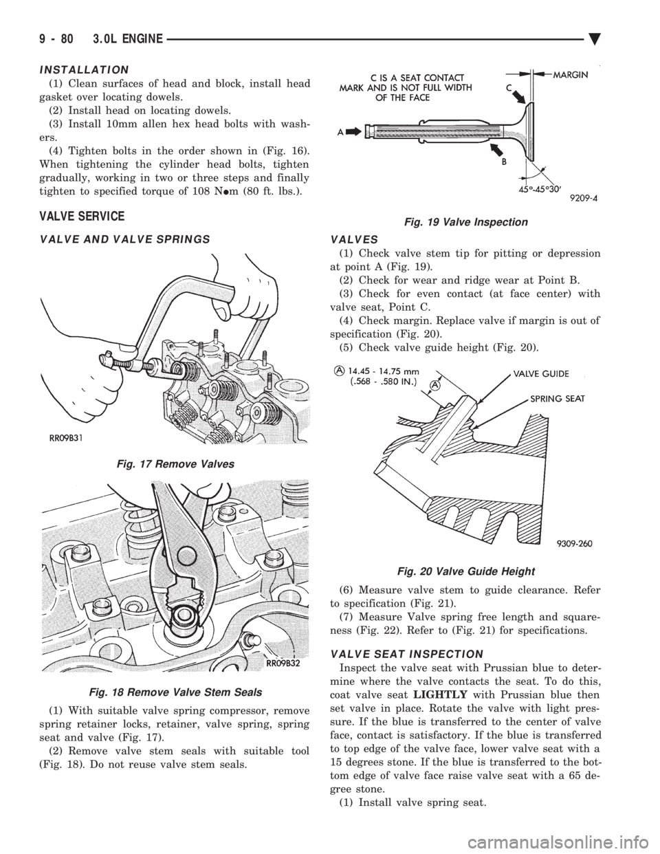
ers. (4) Tighten bolts in the order shown in (Fig. 16).
When tightening the cylinder head bolts, tighten
gradually, working in two or three steps and finally
tighten to specified torque of 108 N Im (80 ft. lbs.).
VALVE SERVICE
VALVE AND VALVE SPRINGS
(1) With suitable valve spring compressor, remove
spring retainer locks, retainer, valve spring, spring
seat and valve (Fig. 17). (2) Remove valve stem seals with suitable tool
(Fig. 18). Do not reuse valve stem seals.
VALVES
(1) Check valve stem tip for pitting or depression
at point A (Fig. 19). (2) Check for wear and ridge wear at Point B.
(3) Check for even contact (at face center) with
valve seat, Point C. (4) Check margin. Replace valve if margin is out of
specification (Fig. 20). (5) Check valve guide height (Fig. 20).
(6) Measure valve stem to guide clearance. Refer
to specification (Fig. 21). (7) Measure Valve spring free length and square-
ness (Fig. 22). Refer to (Fig. 21) for specifications.
VALVE SEAT INSPECTION
Inspect the valve seat with Prussian blue to deter-
mine where the valve contacts the seat. To do this,
coat valve seat LIGHTLYwith Prussian blue then
set valve in place. Rotate the valve with light pres-
sure. If the blue is transferred to the center of valve
face, contact is satisfactory. If the blue is transferred
to top edge of the valve face, lower valve seat with a
15 degrees stone. If the blue is transferred to the bot-
tom edge of valve face raise valve seat with a 65 de-
gree stone. (1) Install valve spring seat.
Fig. 17 Remove Valves
Fig. 18 Remove Valve Stem Seals
Fig. 19 Valve Inspection
Fig. 20 Valve Guide Height
9 - 80 3.0L ENGINE Ä
Page 1649 of 2438
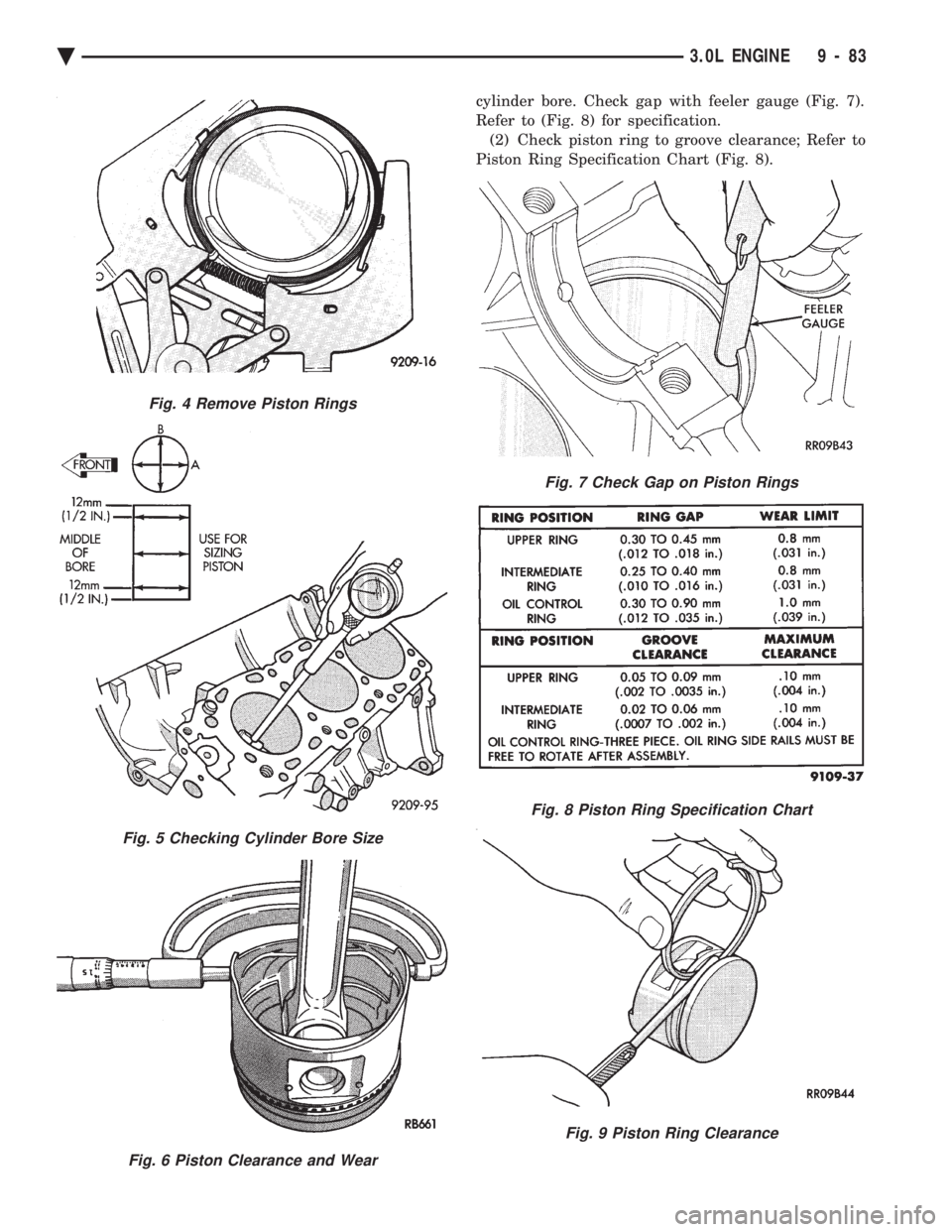
cylinder bore. Check gap with feeler gauge (Fig. 7).
Refer to (Fig. 8) for specification.(2) Check piston ring to groove clearance; Refer to
Piston Ring Specification Chart (Fig. 8).
Fig. 4 Remove Piston Rings
Fig. 5 Checking Cylinder Bore Size
Fig. 6 Piston Clearance and Wear
Fig. 7 Check Gap on Piston Rings
Fig. 8 Piston Ring Specification Chart
Fig. 9 Piston Ring Clearance
Ä 3.0L ENGINE 9 - 83