1993 CHEVROLET PLYMOUTH ACCLAIM check engine
[x] Cancel search: check enginePage 1674 of 2438
(15) Install rocker arm covers tighten screws to 14
N Im (120 in. lbs.) and connector to ignition coils.
(16) Install Intake Manifold; Refer to Intake Mani-
fold Installation 3.3/3.8L Engine, Group 11 Exhaust
System and Intake Manifold.
HYDRAULIC TAPPETS
The valve train includes roller tappet assemblies,
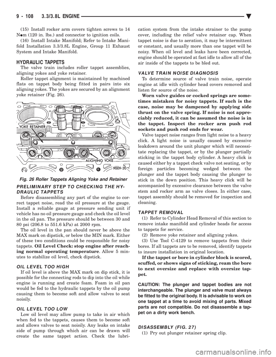
aligning yokes and yoke retainer. Roller tappet alignment is maintained by machined
flats on tappet body being fitted in pairs into six
aligning yokes. The yokes are secured by an alignment
yoke retainer (Fig. 26).
PRELIMINARY STEP TO CHECKING THE HY- DRAULIC TAPPETS
Before disassembling any part of the engine to cor-
rect tappet noise, read the oil pressure at the gauge.
Install a reliable gauge at pressure sending unit if
vehicle has no oil pressure gauge and check the oil level
in the oil pan. The pressure should be between 30 and
80 psi (206.8 to 551.6 kPa) at 2000 rpm. The oil level in the pan should never be above the
MAX mark on dipstick, or below the MIN mark. Either
of these two conditions could be responsible for noisy
tappets. Oil Level Check: stop engine after reach-
ing normal operating temperature . Allow 5 min-
utes to stabilize oil level, check dipstick.
OIL LEVEL TOO HIGH
If oil level is above the MAX mark on dip stick, it is
possible for the connecting rods to dip into the oil while
engine is running and create foam. Foam in oil pan
would be fed to the hydraulic tappets by the oil pump
causing them to become soft and allow valves to seat
noisily.
OIL LEVEL TOO LOW
Low oil level may allow pump to take in air which
when fed to the tappets, causes them to become soft
and allows valves to seat noisily. Any leaks on intake
side of pump through which air can be drawn will
create the same tappet action. Check the lubri- cation system from the intake strainer to the pump
cover, including the relief valve retainer cap. When
tappet noise is due to aeration, it may be intermittent
or constant, and usually more than one tappet will be
noisy. When oil level and leaks have been corrected,
engine should be operated at fast idle to allow all of the
air inside of the tappets to be bled out.
VALVE TRAIN NOISE DIAGNOSIS
To determine source of valve train noise, operate
engine at idle with cylinder head covers removed and
listen for source of the noise. Worn valve guides or cocked springs are some-
times mistaken for noisy tappets. If such is the
case, noise may be dampened by applying side
thrust on the valve spring. If noise is not appre-
ciably reduced, it can be assumed the noise is in
the tappet. Inspect the rocker arm push rod
sockets and push rod ends for wear. Valve tappet noise ranges from light noise to a heavy
click. A light noise is usually caused by excessive
leakdown around the unit plunger which will necessi-
tate replacing the tappet, or by the plunger partially
sticking in the tappet body cylinder. A heavy click is
caused either by a tappet check valve not seating, or by
foreign particles becoming wedged between the
plunger and the tappet body causing the plunger to
stick in the down position. This heavy click will be
accompanied by excessive clearance between the valve
stem and rocker arm as valve closes. In either case,
tappet assembly should be removed for inspection and
cleaning.
TAPPET REMOVAL
(1) Refer to Cylinder Head Removal of this section to
remove intake manifold and cylinder heads for access
to tappets for service. (2) Remove yoke retainer and aligning yokes.
(3) Use Tool C-4129 to remove tappets from their
bores. If all tappets are to be removed, identify tappets
to insure installation in original location. If the tappet or bore in cylinder block is scored,
scuffed, or shows signs of sticking, ream the bore
to next oversize and replace with oversize tap-
pet.
CAUTION: The plunger and tappet bodies are not
interchangeable. The plunger and valve must always
be fitted to the original body. It is advisable to work on
one tappet at a time to avoid mixing of parts. Mixed
parts are not compatible. Do not disassemble a tap-
pet on a dirty work bench.
DISASSEMBLY (FIG. 27)
(1) Pry out plunger retainer spring clip.
Fig. 26 Roller Tappets Aligning Yoke and Retainer
9 - 108 3.3/3.8L ENGINE Ä
Page 1675 of 2438
(2) Clean varnish deposits from inside of tappet
body above plunger cap. (3) Invert tappet body and remove plunger cap,
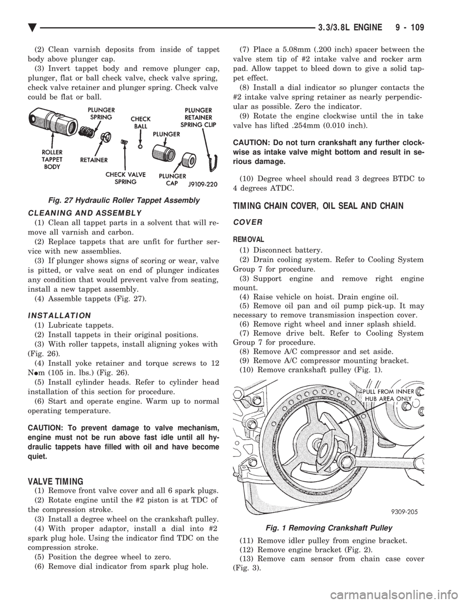
plunger, flat or ball check valve, check valve spring,
check valve retainer and plunger spring. Check valve
could be flat or ball.
CLEANING AND ASSEMBLY
(1) Clean all tappet parts in a solvent that will re-
move all varnish and carbon. (2) Replace tappets that are unfit for further ser-
vice with new assemblies. (3) If plunger shows signs of scoring or wear, valve
is pitted, or valve seat on end of plunger indicates
any condition that would prevent valve from seating,
install a new tappet assembly. (4) Assemble tappets (Fig. 27).
INSTALLATION
(1) Lubricate tappets.
(2) Install tappets in their original positions.
(3) With roller tappets, install aligning yokes with
(Fig. 26). (4) Install yoke retainer and torque screws to 12
N Im (105 in. lbs.) (Fig. 26).
(5) Install cylinder heads. Refer to cylinder head
installation of this section for procedure. (6) Start and operate engine. Warm up to normal
operating temperature.
CAUTION: To prevent damage to valve mechanism,
engine must not be run above fast idle until all hy-
draulic tappets have filled with oil and have become
quiet.
VALVE TIMING
(1) Remove front valve cover and all 6 spark plugs.
(2) Rotate engine until the #2 piston is at TDC of
the compression stroke. (3) Install a degree wheel on the crankshaft pulley.
(4) With proper adaptor, install a dial into #2
spark plug hole. Using the indicator find TDC on the
compression stroke. (5) Position the degree wheel to zero.
(6) Remove dial indicator from spark plug hole. (7) Place a 5.08mm (.200 inch) spacer between the
valve stem tip of #2 intake valve and rocker arm
pad. Allow tappet to bleed down to give a solid tap-
pet effect. (8) Install a dial indicator so plunger contacts the
#2 intake valve spring retainer as nearly perpendic-
ular as possible. Zero the indicator. (9) Rotate the engine clockwise until the in take
valve has lifted .254mm (0.010 inch).
CAUTION: Do not turn crankshaft any further clock-
wise as intake valve might bottom and result in se-
rious damage.
(10) Degree wheel should read 3 degrees BTDC to
4 degrees ATDC.
TIMING CHAIN COVER, OIL SEAL AND CHAIN
COVER
REMOVAL
(1) Disconnect battery.
(2) Drain cooling system. Refer to Cooling System
Group 7 for procedure. (3) Support engine and remove right engine
mount. (4) Raise vehicle on hoist. Drain engine oil.
(5) Remove oil pan and oil pump pick-up. It may
necessary to remove transmission inspection cover. (6) Remove right wheel and inner splash shield.
(7) Remove drive belt. Refer to Cooling System
Group 7 for procedure. (8) Remove A/C compressor and set aside.
(9) Remove A/C compressor mounting bracket.
(10) Remove crankshaft pulley (Fig. 1).
(11) Remove idler pulley from engine bracket.
(12) Remove engine bracket (Fig. 2).
(13) Remove cam sensor from chain case cover
(Fig. 3).
Fig. 27 Hydraulic Roller Tappet Assembly
Fig. 1 Removing Crankshaft Pulley
Ä 3.3/3.8L ENGINE 9 - 109
Page 1676 of 2438
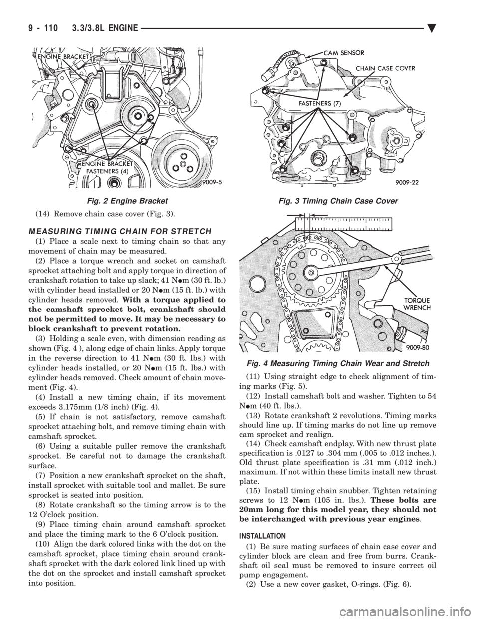
(14) Remove chain case cover (Fig. 3).
MEASURING TIMING CHAIN FOR STRETCH
(1) Place a scale next to timing chain so that any
movement of chain may be measured. (2) Place a torque wrench and socket on camshaft
sprocket attaching bolt and apply torque in direction of
crankshaft rotation to take up slack; 41 N Im (30 ft. lb.)
with cylinder head installed or 20 N Im (15 ft. lb.) with
cylinder heads removed. With a torque applied to
the camshaft sprocket bolt, crankshaft should
not be permitted to move. It may be necessary to
block crankshaft to prevent rotation. (3) Holding a scale even, with dimension reading as
shown (Fig. 4 ), along edge of chain links. Apply torque
in the reverse direction to 41 N Im (30 ft. lbs.) with
cylinder heads installed, or 20 N Im (15 ft. lbs.) with
cylinder heads removed. Check amount of chain move-
ment (Fig. 4). (4) Install a new timing chain, if its movement
exceeds 3.175mm (1/8 inch) (Fig. 4). (5) If chain is not satisfactory, remove camshaft
sprocket attaching bolt, and remove timing chain with
camshaft sprocket. (6) Using a suitable puller remove the crankshaft
sprocket. Be careful not to damage the crankshaft
surface. (7) Position a new crankshaft sprocket on the shaft,
install sprocket with suitable tool and mallet. Be sure
sprocket is seated into position. (8) Rotate crankshaft so the timing arrow is to the
12 O'clock position. (9) Place timing chain around camshaft sprocket
and place the timing mark to the 6 O'clock position. (10) Align the dark colored links with the dot on the
camshaft sprocket, place timing chain around crank-
shaft sprocket with the dark colored link lined up with
the dot on the sprocket and install camshaft sprocket
into position. (11) Using straight edge to check alignment of tim-
ing marks (Fig. 5). (12) Install camshaft bolt and washer. Tighten to 54
N Im (40 ft. lbs.).
(13) Rotate crankshaft 2 revolutions. Timing marks
should line up. If timing marks do not line up remove
cam sprocket and realign. (14) Check camshaft endplay. With new thrust plate
specification is .0127 to .304 mm (.005 to .012 inches.).
Old thrust plate specification is .31 mm (.012 inch.)
maximum. If not within these limits install new thrust
plate. (15) Install timing chain snubber. Tighten retaining
screws to 12 N Im (105 in. lbs.). These bolts are
20mm long for this model year, they should not
be interchanged with previous year engines .
INSTALLATION (1) Be sure mating surfaces of chain case cover and
cylinder block are clean and free from burrs. Crank-
shaft oil seal must be removed to insure correct oil
pump engagement. (2) Use a new cover gasket, O-rings. (Fig. 6).
Fig. 3 Timing Chain Case Cover
Fig. 4 Measuring Timing Chain Wear and Stretch
Fig. 2 Engine Bracket
9 - 110 3.3/3.8L ENGINE Ä
Page 1678 of 2438
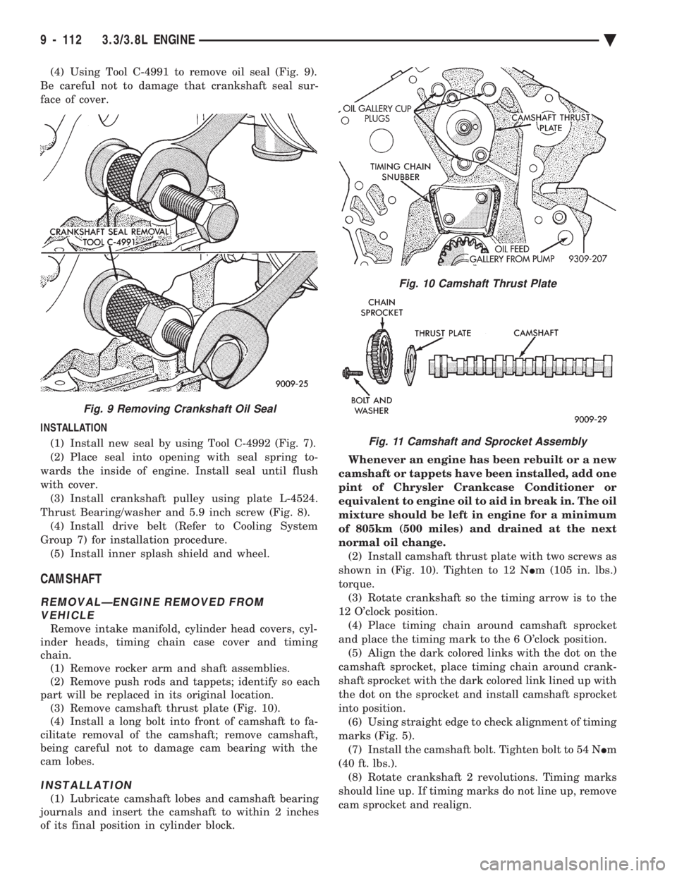
(4) Using Tool C-4991 to remove oil seal (Fig. 9).
Be careful not to damage that crankshaft seal sur-
face of cover.
INSTALLATION (1) Install new seal by using Tool C-4992 (Fig. 7).
(2) Place seal into opening with seal spring to-
wards the inside of engine. Install seal until flush
with cover. (3) Install crankshaft pulley using plate L-4524.
Thrust Bearing/washer and 5.9 inch screw (Fig. 8). (4) Install drive belt (Refer to Cooling System
Group 7) for installation procedure. (5) Install inner splash shield and wheel.
CAMSHAFT
REMOVALÐENGINE REMOVED FROM VEHICLE
Remove intake manifold, cylinder head covers, cyl-
inder heads, timing chain case cover and timing
chain. (1) Remove rocker arm and shaft assemblies.
(2) Remove push rods and tappets; identify so each
part will be replaced in its original location. (3) Remove camshaft thrust plate (Fig. 10).
(4) Install a long bolt into front of camshaft to fa-
cilitate removal of the camshaft; remove camshaft,
being careful not to damage cam bearing with the
cam lobes.
INSTALLATION
(1) Lubricate camshaft lobes and camshaft bearing
journals and insert the camshaft to within 2 inches
of its final position in cylinder block. Whenever an engine has been rebuilt or a new
camshaft or tappets have been installed, add one
pint of Chrysler Crankcase Conditioner or
equivalent to engine oil to aid in break in. The oil
mixture should be left in engine for a minimum
of 805km (500 miles) and drained at the next
normal oil change. (2) Install camshaft thrust plate with two screws as
shown in (Fig. 10). Tighten to 12 N Im (105 in. lbs.)
torque. (3) Rotate crankshaft so the timing arrow is to the
12 O'clock position. (4) Place timing chain around camshaft sprocket
and place the timing mark to the 6 O'clock position. (5) Align the dark colored links with the dot on the
camshaft sprocket, place timing chain around crank-
shaft sprocket with the dark colored link lined up with
the dot on the sprocket and install camshaft sprocket
into position. (6) Using straight edge to check alignment of timing
marks (Fig. 5). (7) Install the camshaft bolt. Tighten bolt to 54 N Im
(40 ft. lbs.). (8) Rotate crankshaft 2 revolutions. Timing marks
should line up. If timing marks do not line up, remove
cam sprocket and realign.
Fig. 9 Removing Crankshaft Oil Seal
Fig. 10 Camshaft Thrust Plate
Fig. 11 Camshaft and Sprocket Assembly
9 - 112 3.3/3.8L ENGINE Ä
Page 1680 of 2438
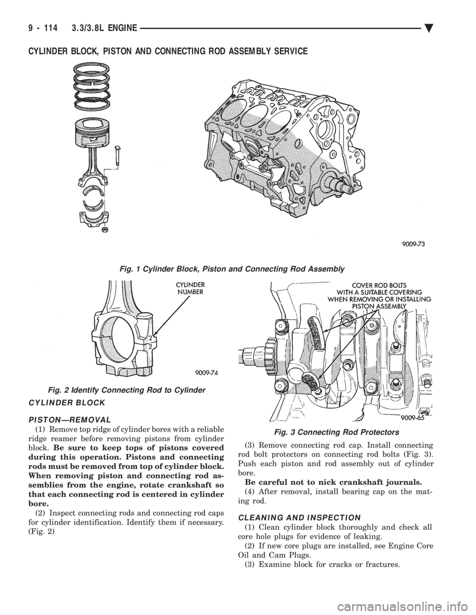
CYLINDER BLOCK, PISTON AND CONNECTING ROD ASSEMBLY SERVICE
CYLINDER BLOCK PISTONÐREMOVAL
(1) Remove top ridge of cylinder bores with a reliable
ridge reamer before removing pistons from cylinder
block. Be sure to keep tops of pistons covered
during this operation. Pistons and connecting
rods must be removed from top of cylinder block.
When removing piston and connecting rod as-
semblies from the engine, rotate crankshaft so
that each connecting rod is centered in cylinder
bore. (2) Inspect connecting rods and connecting rod caps
for cylinder identification. Identify them if necessary.
(Fig. 2) (3) Remove connecting rod cap. Install connecting
rod bolt protectors on connecting rod bolts (Fig. 3).
Push each piston and rod assembly out of cylinder
bore. Be careful not to nick crankshaft journals.
(4) After removal, install bearing cap on the mat-
ing rod.
CLEANING AND INSPECTION
(1) Clean cylinder block thoroughly and check all
core hole plugs for evidence of leaking. (2) If new core plugs are installed, see Engine Core
Oil and Cam Plugs. (3) Examine block for cracks or fractures.
Fig. 1 Cylinder Block, Piston and Connecting Rod Assembly
Fig. 2 Identify Connecting Rod to Cylinder
Fig. 3 Connecting Rod Protectors
9 - 114 3.3/3.8L ENGINE Ä
Page 1681 of 2438
CYLINDER BORE INSPECTION
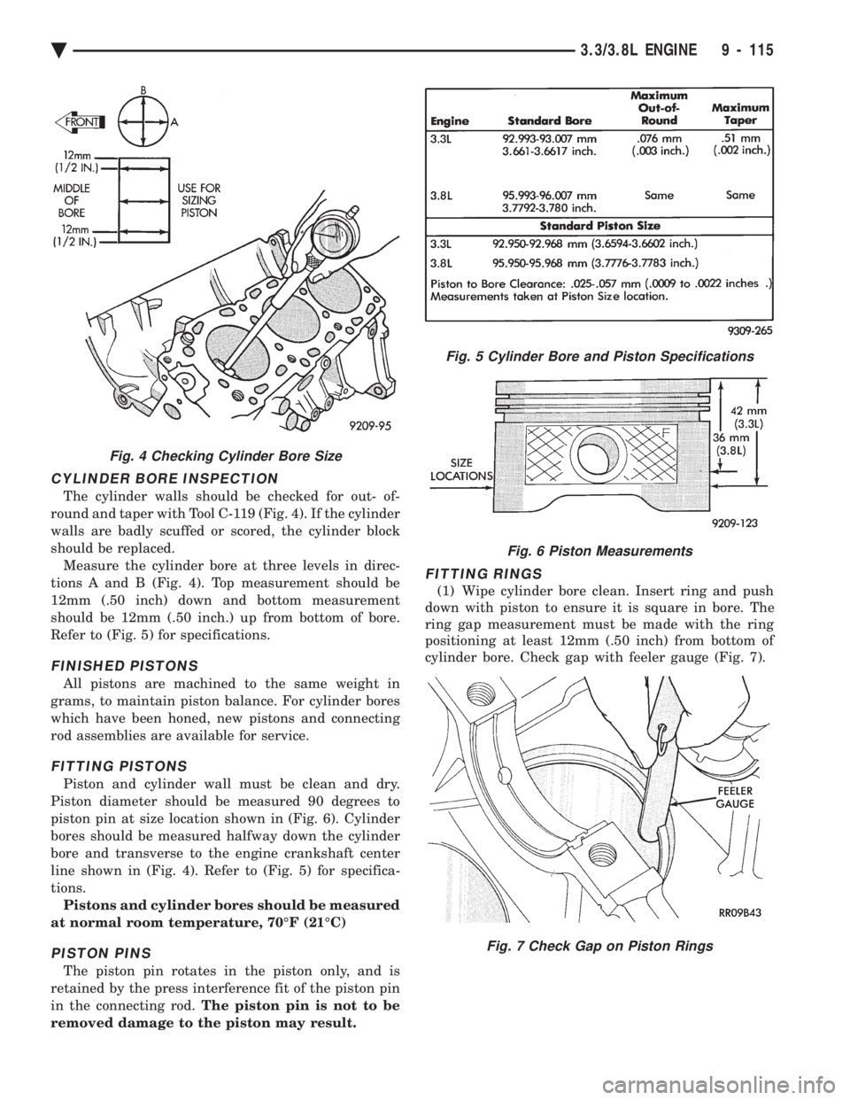
The cylinder walls should be checked for out- of-
round and taper with Tool C-119 (Fig. 4). If the cylinder
walls are badly scuffed or scored, the cylinder block
should be replaced. Measure the cylinder bore at three levels in direc-
tions A and B (Fig. 4). Top measurement should be
12mm (.50 inch) down and bottom measurement
should be 12mm (.50 inch.) up from bottom of bore.
Refer to (Fig. 5) for specifications.
FINISHED PISTONS
All pistons are machined to the same weight in
grams, to maintain piston balance. For cylinder bores
which have been honed, new pistons and connecting
rod assemblies are available for service.
FITTING PISTONS
Piston and cylinder wall must be clean and dry.
Piston diameter should be measured 90 degrees to
piston pin at size location shown in (Fig. 6). Cylinder
bores should be measured halfway down the cylinder
bore and transverse to the engine crankshaft center
line shown in (Fig. 4). Refer to (Fig. 5) for specifica-
tions. Pistons and cylinder bores should be measured
at normal room temperature, 70ÉF (21ÉC)
PISTON PINS
The piston pin rotates in the piston only, and is
retained by the press interference fit of the piston pin
in the connecting rod. The piston pin is not to be
removed damage to the piston may result.
FITTING RINGS
(1) Wipe cylinder bore clean. Insert ring and push
down with piston to ensure it is square in bore. The
ring gap measurement must be made with the ring
positioning at least 12mm (.50 inch) from bottom of
cylinder bore. Check gap with feeler gauge (Fig. 7).
Fig. 5 Cylinder Bore and Piston Specifications
Fig. 6 Piston Measurements
Fig. 7 Check Gap on Piston Rings
Fig. 4 Checking Cylinder Bore Size
Ä 3.3/3.8L ENGINE 9 - 115
Page 1682 of 2438
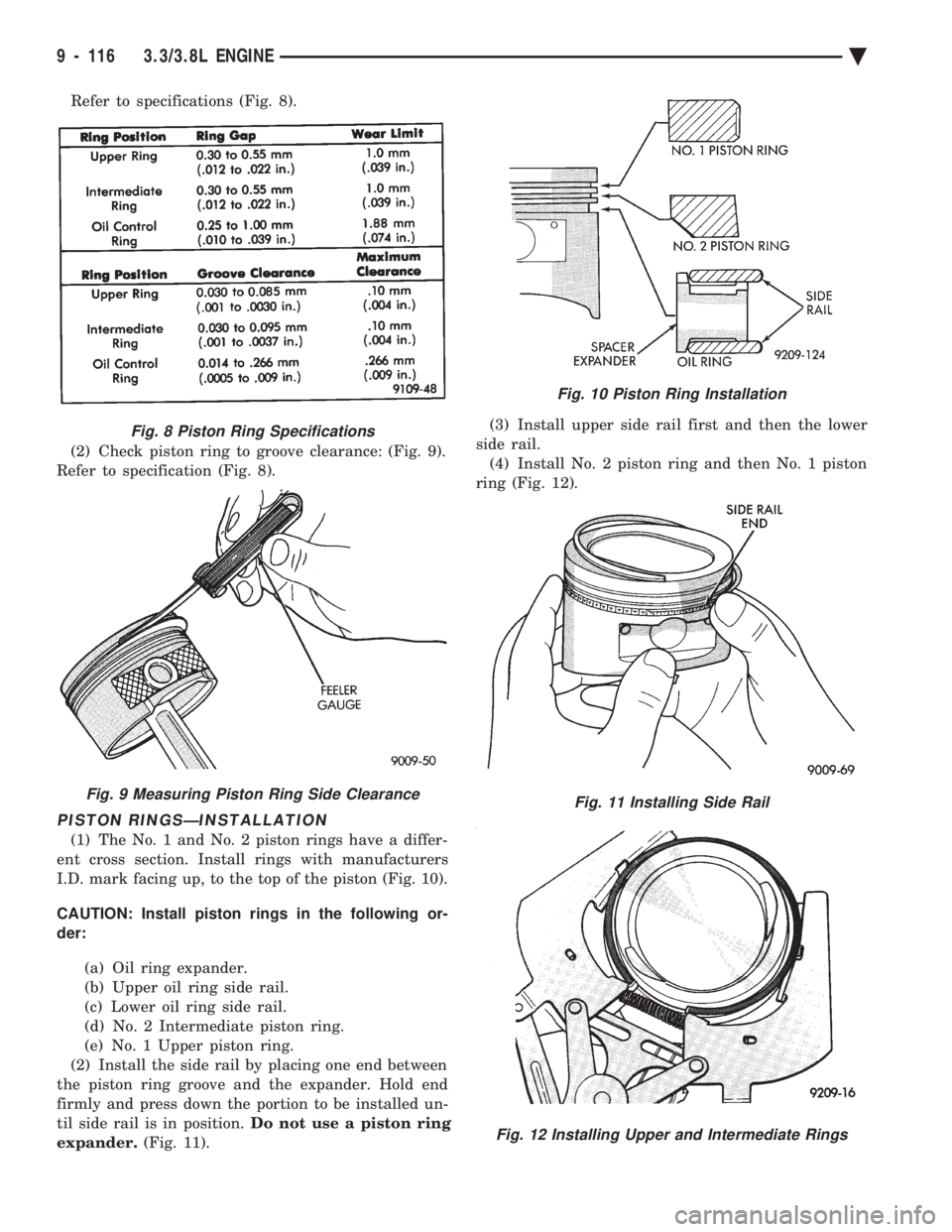
Refer to specifications (Fig. 8).
(2) Check piston ring to groove clearance: (Fig. 9).
Refer to specification (Fig. 8).
PISTON RINGSÐINSTALLATION
(1) The No. 1 and No. 2 piston rings have a differ-
ent cross section. Install rings with manufacturers
I.D. mark facing up, to the top of the piston (Fig. 10).
CAUTION: Install piston rings in the following or-
der:
(a) Oil ring expander.
(b) Upper oil ring side rail.
(c) Lower oil ring side rail.
(d) No. 2 Intermediate piston ring.
(e) No. 1 Upper piston ring.
(2) Install the side rail by placing one end between
the piston ring groove and the expander. Hold end
firmly and press down the portion to be installed un-
til side rail is in position. Do not use a piston ring
expander. (Fig. 11). (3) Install upper side rail first and then the lower
side rail. (4) Install No. 2 piston ring and then No. 1 piston
ring (Fig. 12).
Fig. 8 Piston Ring Specifications
Fig. 9 Measuring Piston Ring Side Clearance
Fig. 10 Piston Ring Installation
Fig. 11 Installing Side Rail
Fig. 12 Installing Upper and Intermediate Rings
9 - 116 3.3/3.8L ENGINE Ä
Page 1683 of 2438
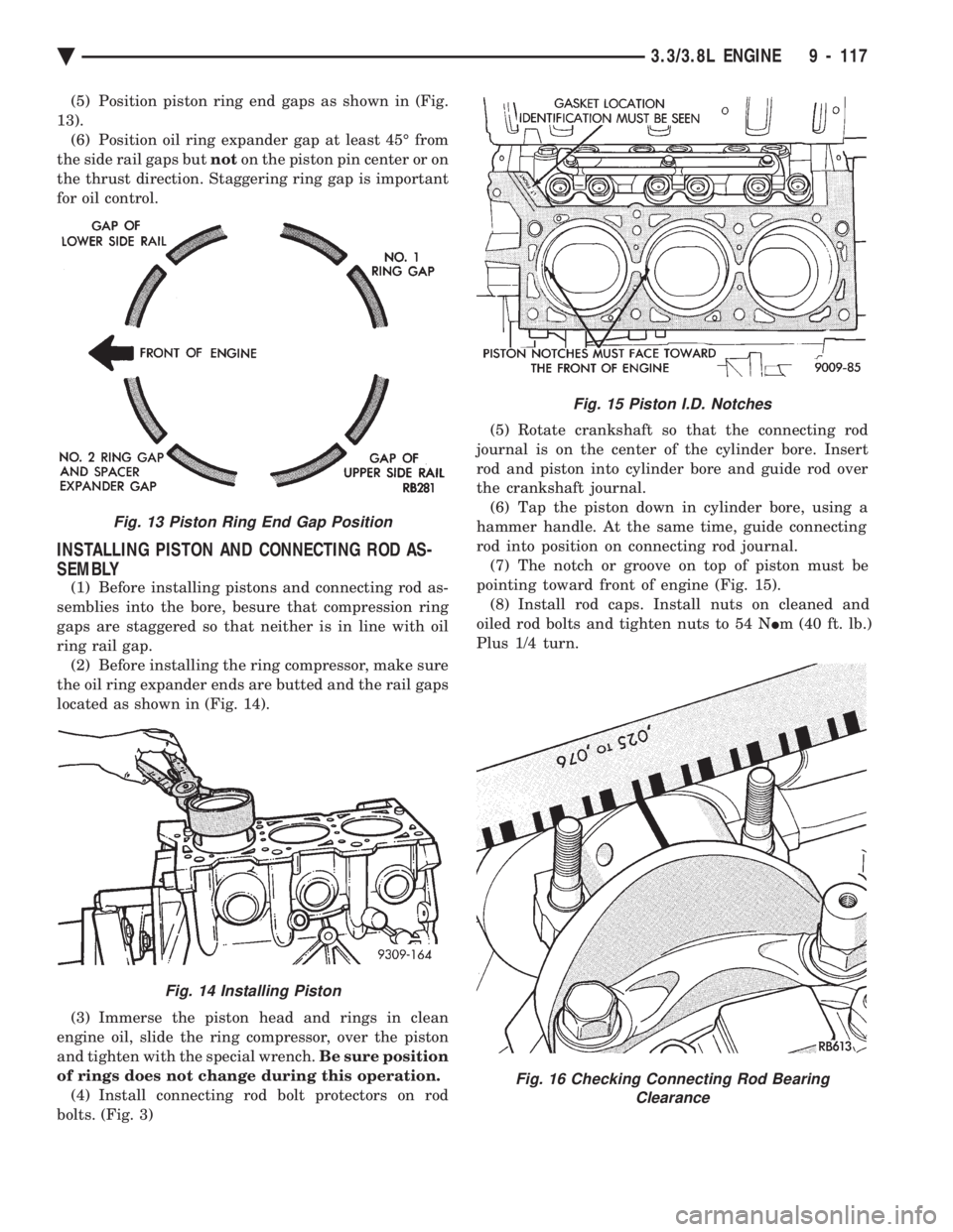
(5) Position piston ring end gaps as shown in (Fig.
13). (6) Position oil ring expander gap at least 45É from
the side rail gaps but noton the piston pin center or on
the thrust direction. Staggering ring gap is important
for oil control.
INSTALLING PISTON AND CONNECTING ROD AS-
SEMBLY
(1) Before installing pistons and connecting rod as-
semblies into the bore, besure that compression ring
gaps are staggered so that neither is in line with oil
ring rail gap. (2) Before installing the ring compressor, make sure
the oil ring expander ends are butted and the rail gaps
located as shown in (Fig. 14).
(3) Immerse the piston head and rings in clean
engine oil, slide the ring compressor, over the piston
and tighten with the special wrench. Be sure position
of rings does not change during this operation. (4) Install connecting rod bolt protectors on rod
bolts. (Fig. 3) (5) Rotate crankshaft so that the connecting rod
journal is on the center of the cylinder bore. Insert
rod and piston into cylinder bore and guide rod over
the crankshaft journal. (6) Tap the piston down in cylinder bore, using a
hammer handle. At the same time, guide connecting
rod into position on connecting rod journal. (7) The notch or groove on top of piston must be
pointing toward front of engine (Fig. 15). (8) Install rod caps. Install nuts on cleaned and
oiled rod bolts and tighten nuts to 54 N Im (40 ft. lb.)
Plus 1/4 turn.
Fig. 15 Piston I.D. Notches
Fig. 16 Checking Connecting Rod Bearing Clearance
Fig. 13 Piston Ring End Gap Position
Fig. 14 Installing Piston
Ä 3.3/3.8L ENGINE 9 - 117