1993 CHEVROLET PLYMOUTH ACCLAIM check engine
[x] Cancel search: check enginePage 1684 of 2438
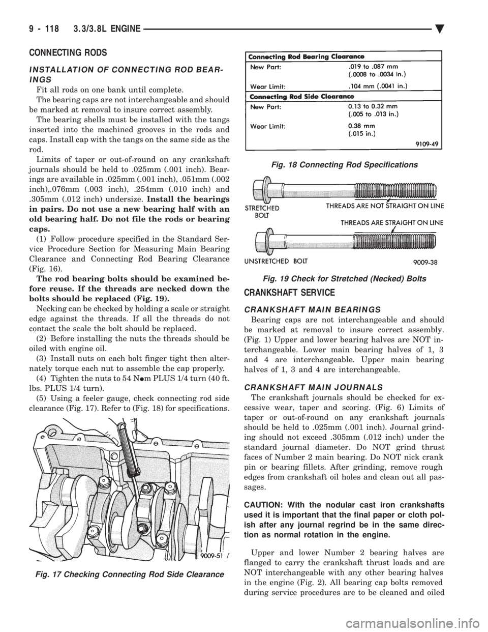
CONNECTING RODS
INSTALLATION OF CONNECTING ROD BEAR- INGS
Fit all rods on one bank until complete.
The bearing caps are not interchangeable and should
be marked at removal to insure correct assembly. The bearing shells must be installed with the tangs
inserted into the machined grooves in the rods and
caps. Install cap with the tangs on the same side as the
rod. Limits of taper or out-of-round on any crankshaft
journals should be held to .025mm (.001 inch). Bear-
ings are available in .025mm (.001 inch), .051mm (.002
inch),.076mm (.003 inch), .254mm (.010 inch) and
.305mm (.012 inch) undersize. Install the bearings
in pairs. Do not use a new bearing half with an
old bearing half. Do not file the rods or bearing
caps. (1) Follow procedure specified in the Standard Ser-
vice Procedure Section for Measuring Main Bearing
Clearance and Connecting Rod Bearing Clearance
(Fig. 16). The rod bearing bolts should be examined be-
fore reuse. If the threads are necked down the
bolts should be replaced (Fig. 19). Necking can be checked by holding a scale or straight
edge against the threads. If all the threads do not
contact the scale the bolt should be replaced. (2) Before installing the nuts the threads should be
oiled with engine oil. (3) Install nuts on each bolt finger tight then alter-
nately torque each nut to assemble the cap properly. (4) Tighten the nuts to 54 N Im PLUS 1/4 turn (40 ft.
lbs. PLUS 1/4 turn). (5) Using a feeler gauge, check connecting rod side
clearance (Fig. 17). Refer to (Fig. 18) for specifications.
CRANKSHAFT SERVICE
CRANKSHAFT MAIN BEARINGS
Bearing caps are not interchangeable and should
be marked at removal to insure correct assembly.
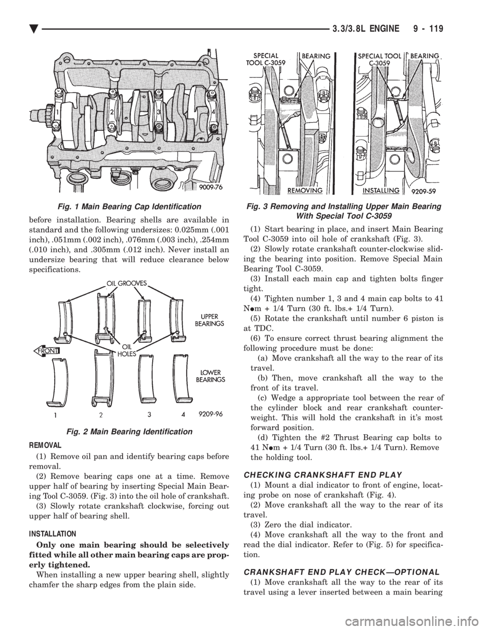
(Fig. 1) Upper and lower bearing halves are NOT in-
terchangeable. Lower main bearing halves of 1, 3
and 4 are interchangeable. Upper main bearing
halves of 1, 3 and 4 are interchangeable.
CRANKSHAFT MAIN JOURNALS
The crankshaft journals should be checked for ex-
cessive wear, taper and scoring. (Fig. 6) Limits of
taper or out-of-round on any crankshaft journals
should be held to .025mm (.001 inch). Journal grind-
ing should not exceed .305mm (.012 inch) under the
standard journal diameter. Do NOT grind thrust
faces of Number 2 main bearing. Do NOT nick crank
pin or bearing fillets. After grinding, remove rough
edges from crankshaft oil holes and clean out all pas-
sages.
CAUTION: With the nodular cast iron crankshafts
used it is important that the final paper or cloth pol-
ish after any journal regrind be in the same direc-
tion as normal rotation in the engine.
Upper and lower Number 2 bearing halves are
flanged to carry the crankshaft thrust loads and are
NOT interchangeable with any other bearing halves
in the engine (Fig. 2). All bearing cap bolts removed
during service procedures are to be cleaned and oiled
Fig. 18 Connecting Rod Specifications
Fig. 19 Check for Stretched (Necked) Bolts
Fig. 17 Checking Connecting Rod Side Clearance
9 - 118 3.3/3.8L ENGINE Ä
Page 1685 of 2438
before installation. Bearing shells are available in
standard and the following undersizes: 0.025mm (.001
inch), .051mm (.002 inch), .076mm (.003 inch), .254mm
(.010 inch), and .305mm (.012 inch). Never install an
undersize bearing that will reduce clearance below
specifications.
REMOVAL (1) Remove oil pan and identify bearing caps before
removal. (2) Remove bearing caps one at a time. Remove
upper half of bearing by inserting Special Main Bear-
ing Tool C-3059. (Fig. 3) into the oil hole of crankshaft. (3) Slowly rotate crankshaft clockwise, forcing out
upper half of bearing shell.
INSTALLATION Only one main bearing should be selectively
fitted while all other main bearing caps are prop-
erly tightened. When installing a new upper bearing shell, slightly
chamfer the sharp edges from the plain side. (1) Start bearing in place, and insert Main Bearing
Tool C-3059 into oil hole of crankshaft (Fig. 3). (2) Slowly rotate crankshaft counter-clockwise slid-
ing the bearing into position. Remove Special Main
Bearing Tool C-3059. (3) Install each main cap and tighten bolts finger
tight. (4) Tighten number 1, 3 and 4 main cap bolts to 41
N Im + 1/4 Turn (30 ft. lbs.+ 1/4 Turn).
(5) Rotate the crankshaft until number 6 piston is
at TDC. (6) To ensure correct thrust bearing alignment the
following procedure must be done: (a) Move crankshaft all the way to the rear of its
travel. (b) Then, move crankshaft all the way to the
front of its travel. (c) Wedge a appropriate tool between the rear of
the cylinder block and rear crankshaft counter-
weight. This will hold the crankshaft in it's most
forward position. (d) Tighten the #2 Thrust Bearing cap bolts to
41 N Im + 1/4 Turn (30 ft. lbs.+ 1/4 Turn). Remove
the holding tool.
CHECKING CRANKSHAFT END PLAY
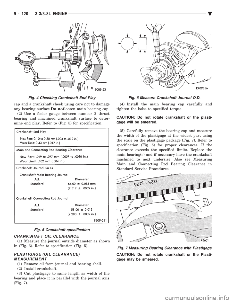
(1) Mount a dial indicator to front of engine, locat-
ing probe on nose of crankshaft (Fig. 4). (2) Move crankshaft all the way to the rear of its
travel. (3) Zero the dial indicator.
(4) Move crankshaft all the way to the front and
read the dial indicator. Refer to (Fig. 5) for specifica-
tion.
CRANKSHAFT END PLAY CHECKÐOPTIONAL
(1) Move crankshaft all the way to the rear of its
travel using a lever inserted between a main bearing
Fig. 3 Removing and Installing Upper Main Bearing With Special Tool C-3059Fig. 1 Main Bearing Cap Identification
Fig. 2 Main Bearing Identification
Ä 3.3/3.8L ENGINE 9 - 119
Page 1686 of 2438
cap and a crankshaft cheek using care not to damage
any bearing surface. Do notloosen main bearing cap.
(2) Use a feeler gauge between number 2 thrust
bearing and machined crankshaft surface to deter-
mine end play. Refer to (Fig. 5) for specification.
CRANKSHAFT OIL CLEARANCE
(1) Measure the journal outside diameter as shown
in (Fig. 6). Refer to specification (Fig. 5).
PLASTIGAGE (OIL CLEARANCE) MEASUREMENT
(1) Remove oil from journal and bearing shell.
(2) Install crankshaft.
(3) Cut plastigage to same length as width of the
bearing and place it in parallel with the journal axis
(Fig. 7). (4) Install the main bearing cap carefully and
tighten the bolts to specified torque.
CAUTION: Do not rotate crankshaft or the plasti-
gage will be smeared.
(5) Carefully remove the bearing cap and measure
the width of the plastigage at the widest part using
the scale on the plastigage package (Fig. 7). Refer to
specification (Fig. 5) for proper clearances. If the
clearance exceeds the specified limits. Replace the
main bearing(s) and if necessary have the crankshaft
machined to next undersize. Also see Measuring
Main and Connecting Rod Bearing Clearance in
Standard Service Procedures.
CAUTION: Do not rotate crankshaft or the Plasti-
gage may be smeared.
Fig. 4 Checking Crankshaft End Play
Fig. 5 Crankshaft specification
Fig. 6 Measure Crankshaft Journal O.D.
Fig. 7 Measuring Bearing Clearance with Plastigage
9 - 120 3.3/3.8L ENGINE Ä
Page 1690 of 2438
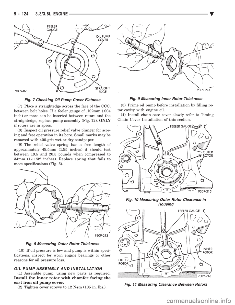
(7) Place a straightedge across the face of the CCC,
between bolt holes. If a feeler gauge of .102mm (.004
inch) or more can be inserted between rotors and the
straightedge, replace pump assembly (Fig. 12). ONLY
if rotors are in specs. (8) Inspect oil pressure relief valve plunger for scor-
ing and free operation in its bore. Small marks may be
removed with 400-grit wet or dry sandpaper. (9) The relief valve spring has a free length of
approximately 49.5mm (1.95 inches) it should test
between 19.5 and 20.5 pounds when compressed to
34mm (1-11/32 inches). Replace spring that fails to
meet specifications (Fig. 5).
(10) If oil pressure is low and pump is within speci-
fications, inspect for worn engine bearings or other
reasons for oil pressure loss.
OIL PUMP ASSEMBLY AND INSTALLATION
(1) Assemble pump, using new parts as required.
Install the inner rotor with chamfer facing the
cast iron oil pump cover. (2) Tighten cover screws to 12 N Im (105 in. lbs.). (3) Prime oil pump before installation by filling ro-
tor cavity with engine oil. (4) Install chain case cover slowly refer to Timing
Chain Cover Installation of this section.
Fig. 9 Measuring Inner Rotor Thickness
Fig. 10 Measuring Outer Rotor Clearance in Housing
Fig. 11 Measuring Clearance Between Rotors
Fig. 7 Checking Oil Pump Cover Flatness
Fig. 8 Measuring Outer Rotor Thickness
9 - 124 3.3/3.8L ENGINE Ä
Page 1691 of 2438
CHECKING ENGINE OIL PRESSURE
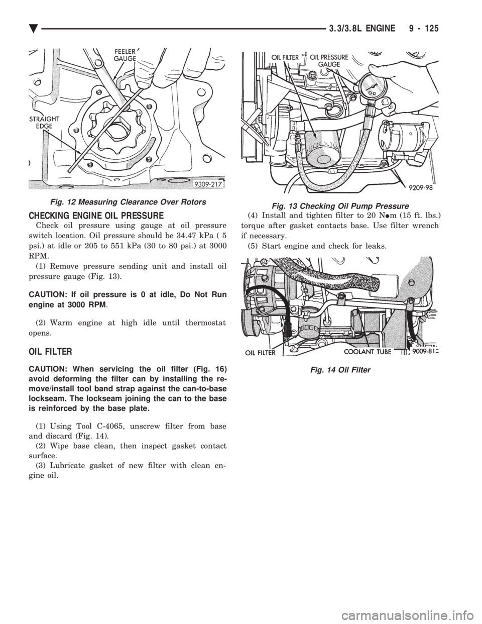
Check oil pressure using gauge at oil pressure
switch location. Oil pressure should be 34.47 kPa ( 5
psi.) at idle or 205 to 551 kPa (30 to 80 psi.) at 3000
RPM. (1) Remove pressure sending unit and install oil
pressure gauge (Fig. 13).
CAUTION: If oil pressure is 0 at idle, Do Not Run
engine at 3000 RPM .
(2) Warm engine at high idle until thermostat
opens.
OIL FILTER
CAUTION: When servicing the oil filter (Fig. 16)
avoid deforming the filter can by installing the re-
move/install tool band strap against the can-to-base
lockseam. The lockseam joining the can to the base
is reinforced by the base plate.
(1) Using Tool C-4065, unscrew filter from base
and discard (Fig. 14). (2) Wipe base clean, then inspect gasket contact
surface. (3) Lubricate gasket of new filter with clean en-
gine oil. (4) Install and tighten filter to 20 N
Im (15 ft. lbs.)
torque after gasket contacts base. Use filter wrench
if necessary. (5) Start engine and check for leaks.
Fig. 12 Measuring Clearance Over RotorsFig. 13 Checking Oil Pump Pressure
Fig. 14 Oil Filter
Ä 3.3/3.8L ENGINE 9 - 125
Page 1703 of 2438
CLEANING AND INSPECTION
(1) Discard gaskets and clean all gasket surfaces
on both manifolds and on cylinder head. (2) Test gasket surfaces of manifolds for flatness
with a straight edge. Surfaces must be flat within
0.15mm per 300mm (.006 in. per foot) of manifold
length. (3) Inspect manifolds for cracks and distortion.
INSTALLATION
(1) Install a new intake and exhaust manifold gas-
ket. Coat steel gasket lightly with Gasket Sealer on
manifold side. Do notcoat composition gasket with
(any) sealer. (2) Set exhaust manifold in place. Tighten retain-
ing nuts starting at center and progressing outward
in both directions to 23 N Im (200 in. lbs.) torque. Re-
peat this procedure until all nuts are at specified
torque. (3) Set intake manifold in place.
(4) Raise vehicle and tighten retaining screws
starting at center and progressing outward in both
directions to 23 N Im (200 in. lbs.) torque (Fig. 3). Re-
peat this procedure until all screws are at specified
torque. (5) Reverse removal procedures 1-9 for installation.
(6) With the DRBII Scan Tool use ASD Fuel Sys-
tem Test to pressurize system to check for leaks.
CAUTION: When using the ASD Fuel System Test,
the Auto Shutdown (ASD) relay will remain ener-
gized for 7 minutes or until the ignition switch is
turned to the OFF position, or Stop All Test is se-
lected.
INTAKE AND EXHAUST MANIFOLDSÐFLEXIBLE
FUEL ENGINE
INTAKE MANIFOLD
The manifold is die-cast aluminum with upper ple-
num and 4 tubes lower runners. These attach to the
cylinder head, with each runner leading directly to a
cylinder. The manifold is also machined for fuel rail attach-
ment and injector installation. The throttle body is
installed on the upper plenum of the manifold.
EXHAUST MANIFOLD
All high strength iron casting that intermesh with
the intake manifold. For standard engines a four
branch design collects and directs exhaust gases to
the conical (articulated joint connection) outlet.
INTAKE/EXHAUST MANIFOLDS
SERVICEÐFLEXIBLE FUEL ENGINES
Intake and exhaust manifolds use a one piece gas-
ket. Service procedures requiring removal and instal-
lation of either must include both manifolds.
SERVICE PRECAUTIONS
Methanol is more toxic than gasoline. Always re-
lease fuel system pressure before servicing fuel sys-
tem components and wear methanol resistant gloves
and eye protection. Avoid breathing methanol vapors or ingesting
methanol. Headaches, dizziness and even uncon-
sciousness could result from breathing these vapors.
Serious injury, blindness and even death could result
from ingesting methanol. Methanol vapors are extremely flammable and can
travel along the ground. Service vehicles in well ven-
tilated areas and avoid ignition sources. Never
smoke while servicing the vehicle. Do not allow methanol to contact skin. Prolonged
contact with methanol can cause dry skin or an al-
lergic skin reaction. Also, prolonged contact could re-
sult in absorption through the skin.
FUEL SYSTEM PRESSURE RELEASE PROCEDURE
WARNING: RELEASE FUEL SYSTEM PRESSURE
BEFORE SERVICING FUEL SYSTEM COMPONENTS.
WEAR METHANOL RESISTANT GLOVES AND EYE
PROTECTION WHILE SERVICING THE FUEL SYS-
TEM.
(a) Disconnect negative cable from battery.
(b) Remove fuel filler cap.
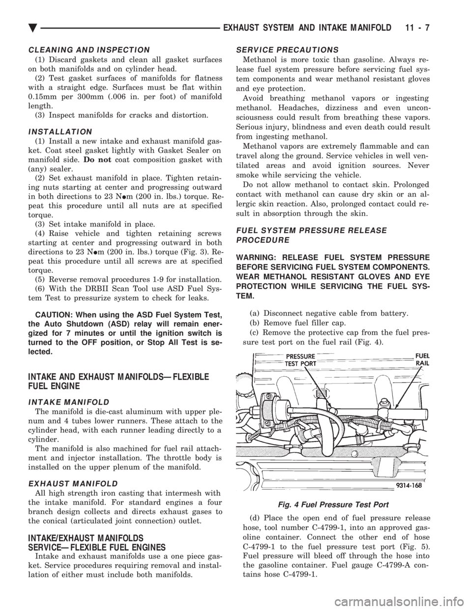
(c) Remove the protective cap from the fuel pres-
sure test port on the fuel rail (Fig. 4).
(d) Place the open end of fuel pressure release
hose, tool number C-4799-1, into an approved gas-
oline container. Connect the other end of hose
C-4799-1 to the fuel pressure test port (Fig. 5).
Fuel pressure will bleed off through the hose into
the gasoline container. Fuel gauge C-4799-A con-
tains hose C-4799-1.
Fig. 4 Fuel Pressure Test Port
Ä EXHAUST SYSTEM AND INTAKE MANIFOLD 11 - 7
Page 1705 of 2438
EXHAUST MANIFOLD
REMOVAL (1) Disconnect exhaust pipe from manifold articu-
late joint. (2) Disconnect the heated oxygen sensor electrical
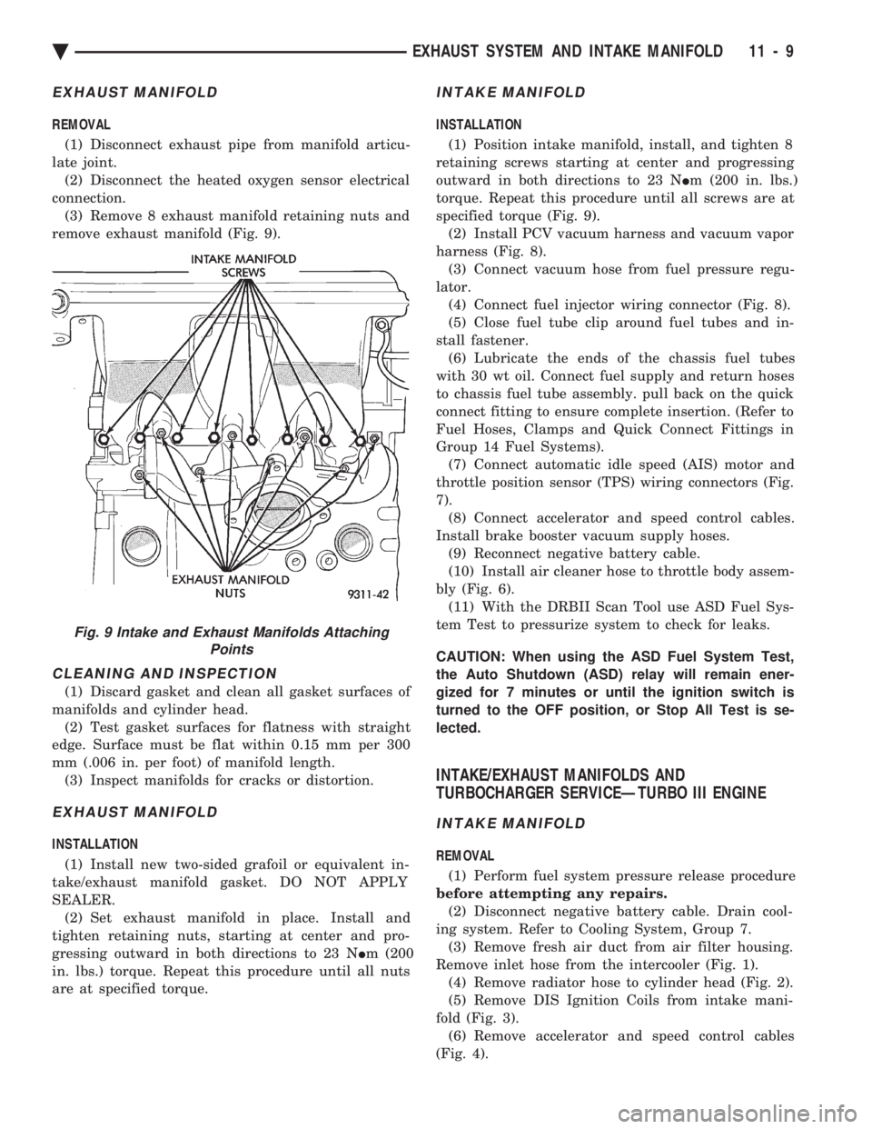
connection. (3) Remove 8 exhaust manifold retaining nuts and
remove exhaust manifold (Fig. 9).
CLEANING AND INSPECTION
(1) Discard gasket and clean all gasket surfaces of
manifolds and cylinder head. (2) Test gasket surfaces for flatness with straight
edge. Surface must be flat within 0.15 mm per 300
mm (.006 in. per foot) of manifold length. (3) Inspect manifolds for cracks or distortion.
EXHAUST MANIFOLD
INSTALLATION
(1) Install new two-sided grafoil or equivalent in-
take/exhaust manifold gasket. DO NOT APPLY
SEALER. (2) Set exhaust manifold in place. Install and
tighten retaining nuts, starting at center and pro-
gressing outward in both directions to 23 N Im (200
in. lbs.) torque. Repeat this procedure until all nuts
are at specified torque.
INTAKE MANIFOLD
INSTALLATION
(1) Position intake manifold, install, and tighten 8
retaining screws starting at center and progressing
outward in both directions to 23 N Im (200 in. lbs.)
torque. Repeat this procedure until all screws are at
specified torque (Fig. 9). (2) Install PCV vacuum harness and vacuum vapor
harness (Fig. 8). (3) Connect vacuum hose from fuel pressure regu-
lator. (4) Connect fuel injector wiring connector (Fig. 8).
(5) Close fuel tube clip around fuel tubes and in-
stall fastener. (6) Lubricate the ends of the chassis fuel tubes
with 30 wt oil. Connect fuel supply and return hoses
to chassis fuel tube assembly. pull back on the quick
connect fitting to ensure complete insertion. (Refer to
Fuel Hoses, Clamps and Quick Connect Fittings in
Group 14 Fuel Systems). (7) Connect automatic idle speed (AIS) motor and
throttle position sensor (TPS) wiring connectors (Fig.
7). (8) Connect accelerator and speed control cables.
Install brake booster vacuum supply hoses. (9) Reconnect negative battery cable.
(10) Install air cleaner hose to throttle body assem-
bly (Fig. 6). (11) With the DRBII Scan Tool use ASD Fuel Sys-
tem Test to pressurize system to check for leaks.
CAUTION: When using the ASD Fuel System Test,
the Auto Shutdown (ASD) relay will remain ener-
gized for 7 minutes or until the ignition switch is
turned to the OFF position, or Stop All Test is se-
lected.
INTAKE/EXHAUST MANIFOLDS AND
TURBOCHARGER SERVICEÐTURBO III ENGINE
INTAKE MANIFOLD
REMOVAL
(1) Perform fuel system pressure release procedure
before attempting any repairs. (2) Disconnect negative battery cable. Drain cool-
ing system. Refer to Cooling System, Group 7. (3) Remove fresh air duct from air filter housing.
Remove inlet hose from the intercooler (Fig. 1). (4) Remove radiator hose to cylinder head (Fig. 2).
(5) Remove DIS Ignition Coils from intake mani-
fold (Fig. 3). (6) Remove accelerator and speed control cables
(Fig. 4).
Fig. 9 Intake and Exhaust Manifolds Attaching Points
Ä EXHAUST SYSTEM AND INTAKE MANIFOLD 11 - 9
Page 1706 of 2438
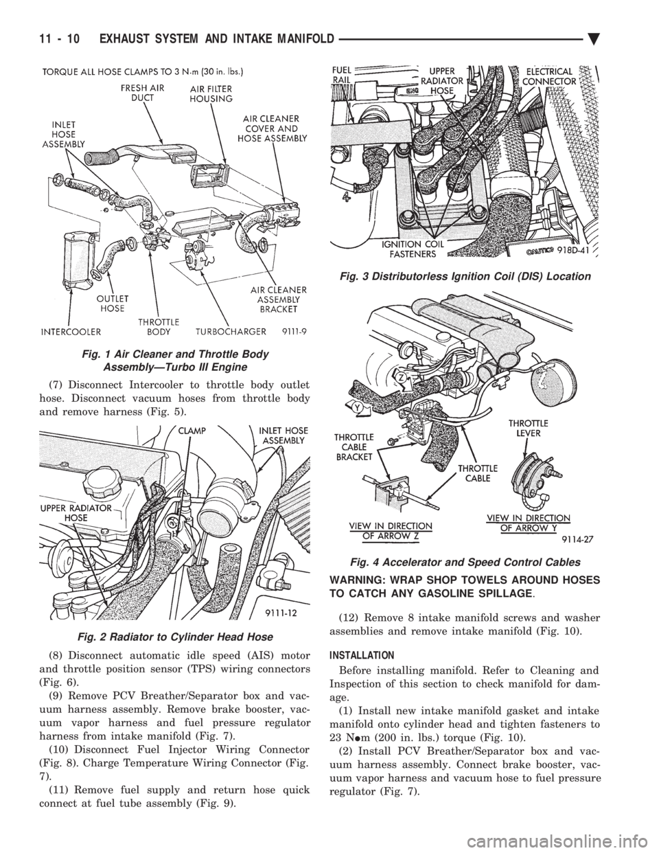
(7) Disconnect Intercooler to throttle body outlet
hose. Disconnect vacuum hoses from throttle body
and remove harness (Fig. 5).
(8) Disconnect automatic idle speed (AIS) motor
and throttle position sensor (TPS) wiring connectors
(Fig. 6). (9) Remove PCV Breather/Separator box and vac-
uum harness assembly. Remove brake booster, vac-
uum vapor harness and fuel pressure regulator
harness from intake manifold (Fig. 7). (10) Disconnect Fuel Injector Wiring Connector
(Fig. 8). Charge Temperature Wiring Connector (Fig.
7). (11) Remove fuel supply and return hose quick
connect at fuel tube assembly (Fig. 9). WARNING: WRAP SHOP TOWELS AROUND HOSES
TO CATCH ANY GASOLINE SPILLAGE
.
(12) Remove 8 intake manifold screws and washer
assemblies and remove intake manifold (Fig. 10).
INSTALLATION
Before installing manifold. Refer to Cleaning and
Inspection of this section to check manifold for dam-
age. (1) Install new intake manifold gasket and intake
manifold onto cylinder head and tighten fasteners to
23 N Im (200 in. lbs.) torque (Fig. 10).
(2) Install PCV Breather/Separator box and vac-
uum harness assembly. Connect brake booster, vac-
uum vapor harness and vacuum hose to fuel pressure
regulator (Fig. 7).
Fig. 1 Air Cleaner and Throttle Body AssemblyÐTurbo III Engine
Fig. 2 Radiator to Cylinder Head Hose
Fig. 3 Distributorless Ignition Coil (DIS) Location
Fig. 4 Accelerator and Speed Control Cables
11 - 10 EXHAUST SYSTEM AND INTAKE MANIFOLD Ä