1993 CHEVROLET PLYMOUTH ACCLAIM relay
[x] Cancel search: relayPage 618 of 2438

(5) For installation reverse above procedure.
(6) Check for proper operation of all components
which are controlled by the pod mounted switch.
TURN SIGNAL AND HAZARD WARNING FLASHER
LOCATION
AA, AC, AP AND AY BODIES
The turn signal flasher and the hazard warning
flasher are two separate plug-in type units. On AC and AY both flashers are on the relay mod-
ule (Fig. 10).
On AA and AP Bodies the hazard flasher is located
on the relay module (Fig. 11). The turn signal flasher
is on the driver's side of A/C duct for AA Body (Fig.
12) and center A/C duct for AP Body.
AG AND AJ BODIES
The turn signal flasher and the hazard warning
flasher are combined into one unit called a combina-
tion flasher (combo-flasher). The combo-flasher con-
trols the flashing of the hazard warning system and the turn signal system. An inoperative bulb or in-
complete turn signal circuit will result in an increase
in flasher speed. The combo-flasher is located under the instrument
panel, right of the steering column and is clipped on
the A/C distribution duct. The combo-flasher is yel-
low in color for ease of identification.TURN SIGNAL RELAYSÐAG AND AJ BODIES
The AG and AJ models are equipped with four
turn signal relays.
Fig. 9 Remote Turn Signal SwitchÐAG and AJ Bodies
Fig. 10 Turn Signal and Hazard WarningFlasherÐAC and AY Bodies
Fig. 11 Hazard Warning FlasherÐAA and AP Bodies
Fig. 12 Turn Signal FlasherÐAA Body
8J - 6 TURN SIGNALS AND HAZARD WARNING FLASHER Ä
Page 619 of 2438
One relay controls the right rear turn signal and
stop lamp. The second relay controls the left rear
turn signal and stop lamp. The third relay controls
the right front turn signal. The fourth relay controls
the left front turn signal. The turn signal relays are located in the relay
bank, underneath the driver's side of the instrument
panel. The four turn signal relays are identical and
can be interchanged. The turn signal relays do not cycle on and off with
the turn signal lamp. Their function is to complete the turn signal circuit when the turn signal is
switched on. Turn signal cycling is done by the com-
bination flasher. To test the relay, remove the suspect relay and
switch it with 1 of the other 3 turn signal relays. If
the problem follows the relay, replace that relay. If
the problem remains in the same circuit, the relay is
not the problem. Refer to Group 8W, Wiring Dia-
grams.
Ä TURN SIGNALS AND HAZARD WARNING FLASHER 8J - 7
Page 621 of 2438
WINDSHIELD WIPER AND WASHER SYSTEMS
CONTENTS
page page
GENERAL WIPER INFORMATION ........... 1
INTERMITTENT WINDSHIELD WIPER MOTOR AND SWITCH SERVICE PROCEDURES .... 12
WINDSHIELD WASHERS ................. 17 WINDSHIELD WIPER BLADE AND ARM SERVICE
PROCEDURES ......................... 1
WINDSHIELD WIPER MOTOR AND LINKAGE ASSEMBLY SERVICE PROCEDURES ....... 3
GENERAL WIPER INFORMATION
WARNING: ON VEHICLES EQUIPPED WITH AIR-
BAG, SEE GROUP 8M, RESTRAINT SYSTEMS FOR
STEERING WHEEL OR COLUMN REMOVAL PROCE-
DURES.
The windshield wipers can be operated with the
windshield wiper switch only when the ignition
switch is in the ACCESSORY or IGNITION position.
A fuse, located in the fuse block, protects the cir-
cuitry of the wiper system and the vehicle. The wiper motor has permanent magnet fields. The speeds are determined by current flow to the appro-
priate set of brushes. The intermittent wipe system, in addition to low
and high speed, has a delay mode. The delay mode
has a range of 2 to 15 seconds. This is accomplished
by a variable resistor in the wiper switch and is con-
trolled electrically by a relay. The wiper system completes the wipe cycle when
the switch is turned OFF. The blades park in the
lowest portion of the wipe pattern.
WINDSHIELD WIPER BLADE AND ARM SERVICE PROCEDURES
WIPER BLADES
Wiper blades, exposed to the weather for a long pe-
riod of time, tend to lose their wiping effectiveness.
Periodic cleaning of the wiper blade is suggested to
remove the accumulation of salt and road film. The
wiper blades, arms, and windshield should be cleaned
with a sponge or cloth and a mild detergent or nona-
brasive cleaner. If the blades continue to streak or
smear, they should be replaced.
WIPER BLADE ELEMENT CHANGE
(1) Turn wiper switch ON, position blades to a con-
venient place by turning the ignition switch ON and
OFF. (2) Lift wiper arm to raise blade off glass.
(3) Remove blade assembly from arm by inserting
a small screwdriver blade into release slot of wiper
blade and push downward (Fig. 1 and 2), or push re-
lease button (2). (4) To remove wiping element from blade assem-
bly:
² Place blade assembly on a working surface
² Apply pressure backwards to open up the blade as-
sembly (Fig. 3)
² By pushing downward and pulling away remove
the wiping element, or lift tab on one end links and
squeeze link to remove from center bridge.
Fig. 1 Wiper Blade and Element
Fig. 2 Blade Assembly from Arm
Ä WINDSHIELD WIPER AND WASHER SYSTEMS 8K - 1
Page 633 of 2438

CONDITION: WIPERS START TO WIPE, BUT STOP BEFORE ONE COMPLETE CYCLE ANDDO NOT RETURN TO PARK POSITION
PROCEDURE
(1) Verify that motor will park when the column
switch is put in the OFF position. (2) Set wiper control switch to maximum DELAY
and allow motor to run until it stops during the wipe
cycle. When motor stops, disconnect 25-way blue con-
nector from the body controller. (3) Connect positive lead of voltmeter to pin 20 of
blue connector and negative lead to the metal case of
the body controller. (a) If voltmeter reads 0, check wiring for an open
circuit. (b) If voltmeter reads 10 to 15 volts, proceed to
step 4.
(4) Using an ohmmeter or continuity tester; (a) Check for continuity between pins 20 and 24
of blue connector of the body controller. (b) Reverse ohmmeter leads on pins 20 and 24,
again checking for continuity. (c) If continuity between pins 20 and 24 is not
observed in both steps a and b, replace the body
controller.
CONDITION: EXCESSIVE DELAY OF MORE THAN 30 SECONDS OR INADEQUATEVARIATION IN DELAY
PROCEDURE
(1) Variations in delay should be as follows: (a) Minimum delay control to extreme counter-
clockwise position before first detent of 1/2 to 2 sec-
onds. (b) Maximum delay control to extreme clockwise
position before OFF detent of 15 to 25 seconds.
(2) If there is excessive delay or no variations in
delay, remove the wiper motor wiring harness while
the motor is parked in the OFF position. (3) Remove 25-way blue connector from the body
controller. (4) Set wiper control switch to maximum DELAY
position. (5) With ignition switch in ON position, measure
voltage between pin 9 of black connector and a good
ground. (a) If voltmeter reads 0, proceed to step 6.
(b) If voltmeter reads 10 to 15 volts, proceed to
step 7.
(6) Set wiper control switch to minimum DELAY
position and measure voltage between pin 9 of blue
connector and a good ground. If voltmeter reads 0,
check for an open circuit in the intermittent wipe
wiring harness. (7) Remove wiper motor circuit fuse. (8) Using an ohmmeter, measure the resistance be-
tween pins 9 and 22 of the body controller 25-way
black connector. Set the wiper control switch first to
minimum DELAY and then maximum DELAY. (a) If resistance reading at minimum DELAY
setting is between 0 and 15 ohms, and at maxi-
mum DELAY setting the resistance is between
240,000 and 400,000 ohms, replace the body con-
troller. (b) If the resistance values above are not ob-
tained, replace the wiper control switch.
CONDITION: WIPERS DO NOT RUN CONTINUALLY WHEN WASH CONTROL ISOPERATED DURING DELAY MODE
PROCEDURE
(1) Disconnect 25-way blue connector from the
body controller (2) Using a voltmeter, connect the positive lead to
pin 10 of the (Black) connector. Connect negative
lead to the body computer metal case. (3) Set wiper control switch to DELAY position.
(4) Depress wash switch.
(5) If voltage reads 0, check switch relay and wir-
ing. (6) If voltage is between 10 and 15 volts, the prob-
lem is in the body controller.
CONDITION: IN DELAY MODE, WIPERS RUN CONTINUALLY WHEN WASH IS OPERATEDBUT DO NOT PROVIDE FOUR EXTRA WIPESWHEN WASH CONTROL IS RELEASED
PROCEDURE
Replace body controller.
CONDITION: WIPERS START ERRATICALLY DURING DELAY MODE
PROCEDURE
(1) Verify that the ground connection at the in-
strument panel is making a good connection, free
from paint and is tight. (2) Verify that the motor ground strap is making
good contact and that the motor mounting bolts are
tight. (3) Verify that the wiring connections to the body
controller, wiper motor, and wiper motor switch are
tight and free of corrosion. (4) If condition is not corrected, problem is with
the body controller
Ä WINDSHIELD WIPER AND WASHER SYSTEMS 8K - 13
Page 643 of 2438
LAMPS
CONTENTS
page page
BULB APPLICATION TABLE ............... 38
CONCEALED HEADLAMPS ................ 27
EXTERIOR LAMP SWITCHES AND HEADLAMP ALIGNMENT ........................... 3
EXTERIOR LAMP SYSTEMS .............. 25
EXTERIOR LAMPSÐAA BODY ............. 7
EXTERIOR LAMPSÐAC BODY ............ 10 EXTERIOR LAMPSÐAG BODY
............ 14
EXTERIOR LAMPSÐAJ BODY ............ 16
EXTERIOR LAMPSÐAP BODY ............ 19
EXTERIOR LAMPSÐAY-BODY ............ 22
GENERAL INFORMATION .................. 1
ILLUMINATED ENTRY SYSTEM ........... 33
GENERAL INFORMATION
Each vehicle is equipped with lamps used for illumi-
nating and indicating purposes. A circuit must have a
good ground to be complete. Circuit ground occurs
when the lamp socket makes contact with the metal
body. On vehicles with plastic lamps, a wire between
the socket and the body makes the grounds. When changing lamp bulbs, check the socket for
corrosion. If corrosion is present, clean contacts with a
wire brush and coat the inside of the socket with
Mopar tMulti-purpose Grease or equivalent.
CAUTION: Do not touch the glass of halogen bulbs
with fingers or any possibly oily surface, reduced
bulb life will result.
BODY IDENTIFICATION
Throughout this Group, references are made to the
vehicle family or body code. To decode the vehicle
identification plates, refer to the Introduction Section
at the front of this manual.
DIAGNOSTIC PROCEDURES
Begin electrical system failure diagnosis by testing
all related fuses and circuit breakers in the fuse block
and engine compartment. When a vehicle experiences problems with the head-
lamp system, verify the condition of the battery con-
nections, charging system, headlamp bulbs, wire con-
nectors, relay, high beam dimmer switch and headlamp
switch. Refer to Wiring Diagrams manual for compo-
nent locations and circuit information.
SYMPTOM
Headlamps are dim when engine is idling of
with ignition turned OFF. Canada cars must
have lamps ON. ACTION
² Clean battery terminal clamps and posts. Refer to
Group 8B, Battery/Starter/Generator Service for
proper procedures.
² Test charging system output. Refer to Group 8A,
Battery/Starting/Charging Systems Diagnostics for
proper testing procedures.
² Test for high resistance in headlamp circuits.
² Defective headlamp bulb.
SYMPTOM
Bulbs burn out frequently.
ACTION
² Test charging system output. Refer to Group 8A,
Battery/Starting/Charging Systems Diagnostics for
proper testing procedures.
² Check for loose or corroded connector terminals or
splices in headlamp circuits. Refer to Wiring Diagrams
manual for component and splice locations.
SYMPTOM
Headlamps are dim with engine running above
idle. Canada cars must have lamps ON.
ACTION
² Test charging system output. Refer to Group 8A,
Battery/Starting/Charging Systems Diagnostics for
proper testing procedures.
² Test for high resistance in headlamp circuits.
² Defective headlamp bulb.
SYMPTOM
Headlamps flash randomly.
ACTION
² Test for poor circuit ground.
² Test for high resistance in headlamp circuits.
Ä LAMPS 8L - 1
Page 644 of 2438
² Test condition of headlamp relay.
² Check for loose or corroded connector terminals or
splices in headlamp circuits. Refer to Wiring Dia-
grams manual for component and splice locations.
SYMPTOM
Headlamps do not illuminate.
ACTION
² Test for voltage at headlamp bulbs connectors.
² Test headlamp relay.
² Test headlamp switch.
² Test high-beam headlamp dimmer switch.
² Check for loose or corroded connector terminals or
splices in headlamp circuits. Refer to Wiring Dia-
grams manual for component and splice locations.
FOG LAMP DIAGNOSIS
The fog lamp system receives voltage from the
headlamp relay when the low-beam headlamps are turned ON. The high-beam headlamp dimmer switch
when actuated cancels out voltage feed to the fog
lamp circuit. The fog lamp circuit is protected by a
20 amp fuse located in the fuse panel. Refer to Wir-
ing Diagrams manual for component location and cir-
cuit information.
SYMPTOM
Fog lamps do not illuminate.
ACTION
² Test fog lamp bulb.
² Test for voltage at fog lamp connector.
² Test for proper fog lamp ground.
² Test circuit fuse.
² Test fog lamp switch.
² Test high-beam headlamp dimmer switch.
² Test headlamp relay.
² Test for open circuit in wire harness.
8L - 2 LAMPS Ä
Page 652 of 2438
EXTERIOR LAMPSÐAC BODY INDEX
page page
Aero Headlamp Bulb ...................... 10
Aero Headlamp Housing ................... 11
Aero HeadlampsÐAC/D-Body ............... 10
Center High Mounted Stop Lamp (CHMSL) ..... 13
Center High-Mounted Stop Lamp (CHMSL) Bulb . 13
Cornering Lamp Assembly .................. 12
Cornering Lamp Bulb ..................... 12
Front Side Marker BulbÐAC/C-Body .......... 12
Front Side Marker LampÐAC/C-Body ......... 12
Headlamp Diagnosis ...................... 10 Headlamp Sealed BeamÐAC/C Body
......... 10
License Plate Lamp/Bulb ................... 13
Park/Turn Signal Lamp or BulbÐAC/C-Body .... 11
Park/Turn Signal Lamp or BulbÐAC/D-Body .... 11
Rear Side Marker Lamp BulbÐAC/C-Body ..... 13
Rear Side Marker LampÐAC/C-Body ......... 13
Tail, Stop, Turn Signal, Back-Up and Side Marker LampÐAC/D-Body ...................... 12
Tail, Stop, Turn Signal, Back-Up LampÐAC/C or AY/S-Body ............................ 12
HEADLAMP DIAGNOSIS
Refer to the Headlamp Diagnosis at the beginning of
this Group. Refer to Wiring Diagrams Manual for
circuit and component locations.
HEADLAMP SEALED BEAMÐAC/C BODY
REMOVAL
(1) Turn the headlight switch ON.
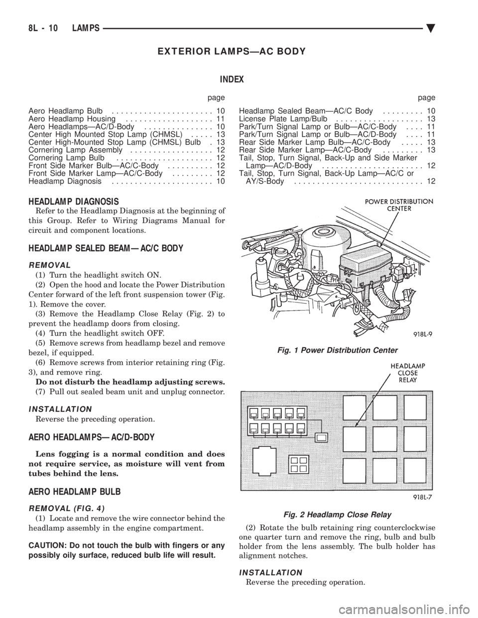
(2) Open the hood and locate the Power Distribution
Center forward of the left front suspension tower (Fig.
1). Remove the cover. (3) Remove the Headlamp Close Relay (Fig. 2) to
prevent the headlamp doors from closing. (4) Turn the headlight switch OFF.
(5) Remove screws from headlamp bezel and remove
bezel, if equipped. (6) Remove screws from interior retaining ring (Fig.
3), and remove ring. Do not disturb the headlamp adjusting screws.
(7) Pull out sealed beam unit and unplug connector.
INSTALLATION
Reverse the preceding operation.
AERO HEADLAMPSÐAC/D-BODY
Lens fogging is a normal condition and does
not require service, as moisture will vent from
tubes behind the lens.
AERO HEADLAMP BULB
REMOVAL (FIG. 4)
(1) Locate and remove the wire connector behind the
headlamp assembly in the engine compartment.
CAUTION: Do not touch the bulb with fingers or any
possibly oily surface, reduced bulb life will result. (2) Rotate the bulb retaining ring counterclockwise
one quarter turn and remove the ring, bulb and bulb
holder from the lens assembly. The bulb holder has
alignment notches.
INSTALLATION
Reverse the preceding operation.
Fig. 1 Power Distribution Center
Fig. 2 Headlamp Close Relay
8L - 10 LAMPS Ä
Page 664 of 2438
EXTERIOR LAMPSÐAY-BODY INDEX
page page
Center High Mounted Stop Lamp ............ 24
Center High Mounted Stop Lamp Bulb (CHMSL) . 24
Cornering Lamp or BulbÐAY/C-P-Body ........ 24
Front Side Marker BulbÐAY/C-P-Body ........ 23
Front Side Marker LampÐAY/C-P-Body ....... 23
General Information ....................... 22
Headlamp Diagnosis ...................... 22 Headlamps
............................. 22
License Plate Lamp or BulbÐAY/C-P-Body ..... 24
Park, Turn Signal Lamp or BulbÐAY/C-P-Body . . 22
Sealed Beam ........................... 22
Tail, Stop, Turn Signal, Side Marker and Back-Up Lamp or BulbÐAY/C-P-Body .............. 24
GENERAL INFORMATION
To service exterior lamps on AY/C-S-Body, refer to
procedures covered in Exterior LampsÐAC-Body sec-
tion. AC/C-S-Body uses the same lamps as AY/C-S-
Body.
HEADLAMPS
Conventional and halogen sealed beams are inter-
changeable, It is not recommended that they be
mixed. The lens, filament and reflector of sealed
beams are molded into one unit.
HEADLAMP DIAGNOSIS
For headlamp diagnosis, refer to the headlamp di-
agnosis chart at the beginning of this Group. Refer to
Wiring Diagrams manual for circuit and component
locations.
SEALED BEAM
REMOVAL
(1) Turn the headlight switch ON.
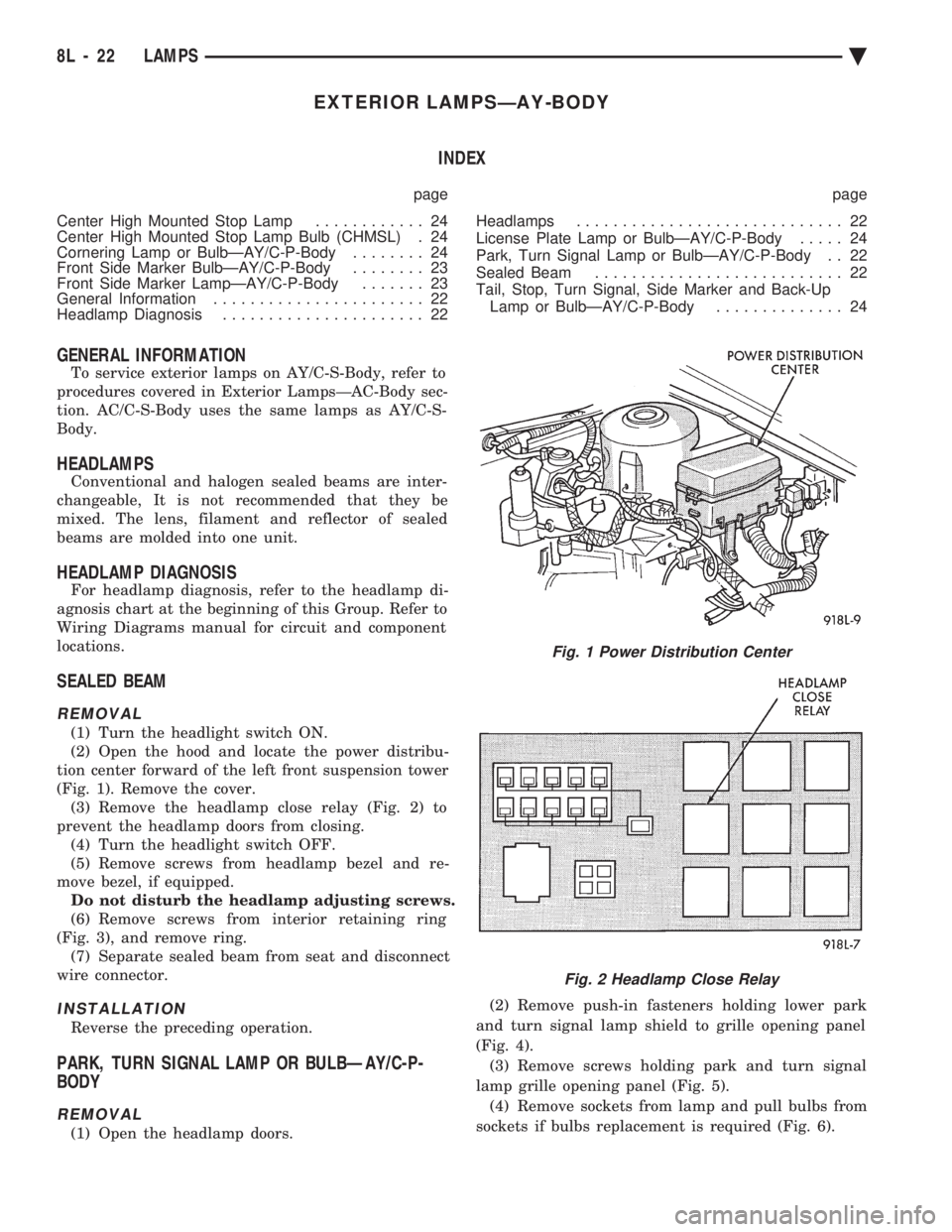
(2) Open the hood and locate the power distribu-
tion center forward of the left front suspension tower
(Fig. 1). Remove the cover. (3) Remove the headlamp close relay (Fig. 2) to
prevent the headlamp doors from closing. (4) Turn the headlight switch OFF.
(5) Remove screws from headlamp bezel and re-
move bezel, if equipped. Do not disturb the headlamp adjusting screws.
(6) Remove screws from interior retaining ring
(Fig. 3), and remove ring. (7) Separate sealed beam from seat and disconnect
wire connector.
INSTALLATION
Reverse the preceding operation.
PARK, TURN SIGNAL LAMP OR BULBÐAY/C-P-
BODY
REMOVAL
(1) Open the headlamp doors. (2) Remove push-in fasteners holding lower park
and turn signal lamp shield to grille opening panel
(Fig. 4). (3) Remove screws holding park and turn signal
lamp grille opening panel (Fig. 5). (4) Remove sockets from lamp and pull bulbs from
sockets if bulbs replacement is required (Fig. 6).
Fig. 1 Power Distribution Center
Fig. 2 Headlamp Close Relay
8L - 22 LAMPS Ä