1993 CHEVROLET PLYMOUTH ACCLAIM relay
[x] Cancel search: relayPage 715 of 2438
above. When the control module has finished, it will
return to the normal operating mode after ten sec-
onds if no further switches are activated.The control module will also return to normal op-
erating mode if any manual seat or recliner move-
ment switch is actuated during the ten second
timeout. If the system has found a problem, refer to the ap-
propriate diagnosis condition.
POWER MEMORY SEAT, RECLINER AND
MIRRORS DIAGNOSIS
Before any diagnosis is done on the system, move
the seat switches and listen for relays clicking in the
control module under the seat. If relays can be heard,
the main battery and ground circuits to the control
module as well as the battery circuit to the switches
in the driver's door are good. When checking for voltage or continuity, always
use a volt/ohm meter to get accurate readings. The
seat and recliner switches must be activated to check
for voltage at the seat and recliner motors or at the
input to the control module from the switches. The control module creates a special voltage supply
for the position sensing functions. It also shuts down
after five seconds, in order to check this or any other
voltage being fed back to the control module. A
switch may have to be activated more than once to
verify a voltage reading. The voltage from the con-
trol module that feeds the seat and recliner position
sensing potentiometer, will be between 4.5 to 5 volts.
For simplicity in the diagnosis section, the feed volt-
age will be called 5 volts. On the position sensing
wires, these voltages will always be less than 5 volts
but more than 0 volts. Typically the high level is at
a maximum of about 4.25 volts and the low level can
be as little as 0.1 volts. If any seat or recliner potentiometer or mirror
rheostat position sense wires are crossed, the control
module will not move that part of the system. The
seat or mirror will be in a fault diagnostic mode.
CONDITION: SYSTEM WILL NOT OPERATE.
PROCEDURE
(1) Check for forward/rearward operation of re-
cliner. If not operable, check for an open or loose cir-
cuit breaker mounted in board on the relay bank in
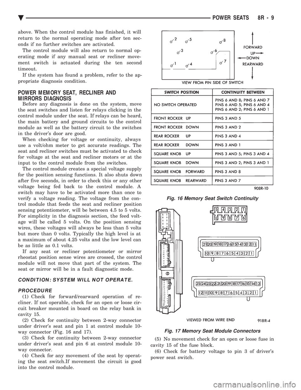
cavity 15. (2) Check for continuity between 2-way connector
under driver's seat and pin 1 at control module 10-
way connector (Fig. 16 and 17). (3) Check for continuity between 2-way connector
under driver's seat and pin 6 at control module 10-
way connector. (4) Check for any movement of the seat by operat-
ing the seat switch.If movement the circuit is good
into the control module. (5) No movement check for an open or loose fuse in
cavity 15 of the fuse block. (6) Check for battery voltage to pin 3 of driver's
power seat switch.
Fig. 16 Memory Seat Switch Continuity
Fig. 17 Memory Seat Module Connectors
Ä POWER SEATS 8R - 9
Page 716 of 2438
(7) If battery is good, check for continuity of driv-
er's power seat switch. Refer to Power Memory Seat
Switch Continuity (Fig. 16). (8) Check that all connectors are securely plugged
into control module under driver's seat with no ter-
minal push outs. (9) No correctable faults are found in the above
steps. The battery voltage and ground circuits are
good into the control module. There is battery volt-
age through the seat switch to the control module.
Then replace the control module. (10) If the control module must be replaced, open it
and observe the non-relay side of the printed circuit
board. The module may be damaged by an intermit-
tent short on the inside of the recliner switch. If a
trace is burnt open near the 10-way connector, may
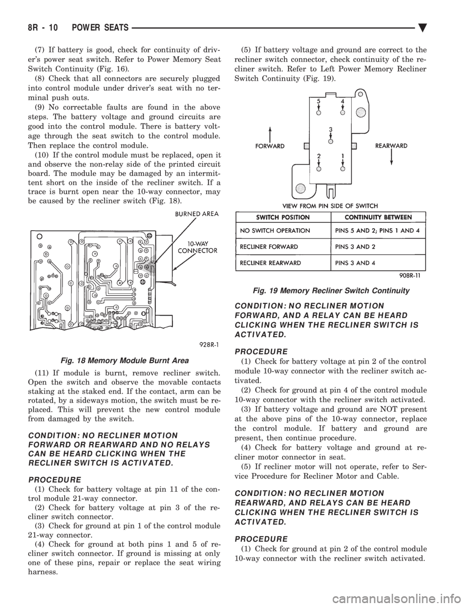
be caused by the recliner switch (Fig. 18).
(11) If module is burnt, remove recliner switch.
Open the switch and observe the movable contacts
staking at the staked end. If the contact, arm can be
rotated, by a sideways motion, the switch must be re-
placed. This will prevent the new control module
from damaged by the switch.
CONDITION: NO RECLINER MOTION FORWARD OR REARWARD AND NO RELAYSCAN BE HEARD CLICKING WHEN THERECLINER SWITCH IS ACTIVATED.
PROCEDURE
(1) Check for battery voltage at pin 11 of the con-
trol module 21-way connector. (2) Check for battery voltage at pin 3 of the re-
cliner switch connector. (3) Check for ground at pin 1 of the control module
21-way connector. (4) Check for ground at both pins 1 and 5 of re-
cliner switch connector. If ground is missing at only
one of these pins, repair or replace the seat wiring
harness. (5) If battery voltage and ground are correct to the
recliner switch connector, check continuity of the re-
cliner switch. Refer to Left Power Memory Recliner
Switch Continuity (Fig. 19).
CONDITION: NO RECLINER MOTION FORWARD, AND A RELAY CAN BE HEARDCLICKING WHEN THE RECLINER SWITCH ISACTIVATED.
PROCEDURE
(1) Check for battery voltage at pin 2 of the control
module 10-way connector with the recliner switch ac-
tivated. (2) Check for ground at pin 4 of the control module
10-way connector with the recliner switch activated. (3) If battery voltage and ground are NOT present
at the above pins of the 10-way connector, replace
the control module. If battery and ground are
present, then continue procedure. (4) Check for battery voltage and ground at re-
cliner motor connector in seat. (5) If recliner motor will not operate, refer to Ser-
vice Procedure for Recliner Motor and Cable.
CONDITION: NO RECLINER MOTION REARWARD, AND RELAYS CAN BE HEARDCLICKING WHEN THE RECLINER SWITCH ISACTIVATED.
PROCEDURE
(1) Check for ground at pin 2 of the control module
10-way connector with the recliner switch activated.
Fig. 18 Memory Module Burnt Area
Fig. 19 Memory Recliner Switch Continuity
8R - 10 POWER SEATS Ä
Page 721 of 2438

(3) Use an ohmmeter to test the wiring between
the door switch and the control module in the driv-
er's seat. The circuits should be disconnected from
their components at each end. Repair the wiring as
required for open circuits, terminal push outs, or bad
crimps. If the circuits are good to the control module
but the function is still missing, replace the control
module.
CONDITION: NO MOVEMENT OF THE SEAT, RELAYS CAN BE HEARD CLICKING WHENTHE SEAT SWITCH IS ACTIVATED.
PROCEDURE
(1) Check for battery voltage and ground at the ap-
propriate pins of the control module 10-way connec-
tor (Fig. 23). If the proper results are not obtained,
replace the control module. If the circuits are correct,
then continue the procedure.
(2) Check for continuity of the motor circuits from
the control module 10-way connector to the left
power seat motor package (Fig. 24). (3) Repair the wiring as required for open circuits,
terminal push outs, or bad crimps. If the circuits are
good but the seat movement direction is still missing,
replace the seat motor package assembly. After re-
placement of the seat motor package, reconnect all wiring connectors and reinstall seat assembly in ve-
hicle. Operate the switches manually to cause maxi-
mum seat movement in all directions. Perform the
memory seat diagnostic self check so the control
module will learn the new soft limits of the assem-
bly.
CONDITION: NO MOVEMENT OF THE MEMORY MIRRORS WHEN THE POWERMIRROR SWITCH IS ACTUATED, MEMORYMIRRORS MOVE DURING RECALL ONLY.
PROCEDURE
(1) Check for battery voltage at pin 1 of the mem-
ory mirror switch 8-way connector in the driver's
door. This battery feed is through a diode package
that is located in the left cowl side area. A grounded
wire on the switch side of the diode would most
likely cause the diode package to open. Solder and
tape the connections if replacement is necessary. The
fuse is in cavity 13 of the fuse block. (2) Check for ground at pin 5 of the memory mir-
ror switch 8-way connector. Repair as needed. (3) Check for continuity of the memory mirror
switch. Refer to the Group 8T, Mirror Switch Test
Procedure and the Continuity.
Fig. 23 Control Module 10-Way Connector Voltage and Ground Test
Fig. 24 Control Module 10-Way Connector to PowerSeat Motor Connector Continuity
Ä POWER SEATS 8R - 15
Page 739 of 2438
² If not remove mirror glass and test the wires for
continuity. If no continuity repair wires.
² If wires are OK, replace mirror glass.
² To test defogger switch refer to Group 8N, Rear
Window Defogger, Control Switch/Timer Relay Mod-
ule Test.
MIRROR SWITCH REPLACEMENTÐAA BODY
(1) Remove door trim panel.
(2) Remove set screw from pillar trim bezel.
(3) Remove pillar trim bezel retaining screws. (4) Disconnect switch wiring (Fig. 9).
(5) Remove switch from switch bezel.
(6) For installation, reverse above procedure.
MIRROR SWITCH REPLACEMENTÐAG AND AJ
BODIES
(1) Carefully pry switch from switch bezel (Fig.
10). (2) Remove switch wiring connector.
(3) For installation, reverse above procedure.
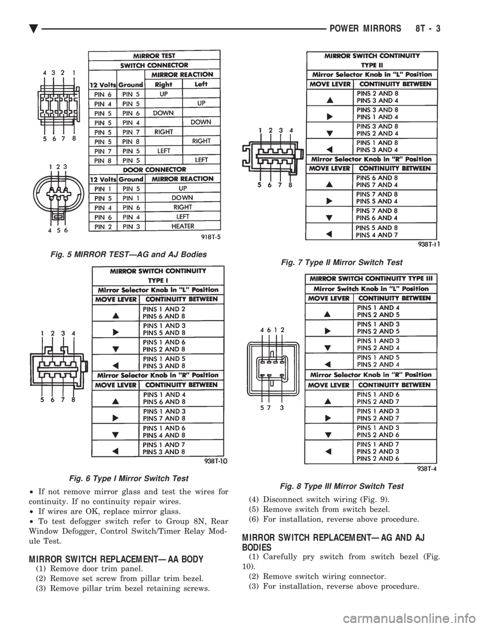
Fig. 5 MIRROR TESTÐAG and AJ Bodies
Fig. 6 Type I Mirror Switch Test
Fig. 7 Type II Mirror Switch Test
Fig. 8 Type III Mirror Switch Test
Ä POWER MIRRORS 8T - 3
Page 744 of 2438
(2) The headlamps and parking lamps should turn
ON for about five seconds.
² AUTO MIRROR LED
² DARK LED
² AUTO LAMP LED
² The LED indicators blink for about 5 seconds.
² If the three indicators continue to blink consider-
ably longer than 5 seconds, then the mirror assembly
is defective. (3) The mirror should change to dim state.(a) Place shift selector in reverse (R), with igni-
tion switch ON:
² AUTO MIRROR LED indicator ON
² DARK LED indicator flashing
² Lasting about 15 seconds
(b) The mirror should slowly change to bright
state. (c) If the ignition is not turned OFF within the
15 second time period, the mirror will reset to its
previous setting.
The previous conditions are OK, the mirror is op-
erating properly. If not OK, continue with voltage tests below.
VOLTAGE TEST
To test for voltage insert voltmeter probe into wire
end of connector to contact terminal. Pin 1 ignition voltage (a) Ignition switch OFF, zero volts.
(b) Ignition switch ON, battery voltage.
Pin 2 battery voltage (a) Battery voltage at all times.
(b) No voltage, check 15 amp. fuse.
Pin 3 Ground (a) Continuity to ground.
(b) No voltage
Pin 4 Reverse over-ride (a) Ignition OFF, zero voltage.
(b) Ignition ON shift selector in Reverse (R), bat-
tery voltage. (c) Ignition ON shift selector in any position
other than Reverse (R), zero voltage.
Pin 5 Headlamp relay (a) Battery voltage at all times from headlamp
relay. (b) No battery voltage, test headlamp relay.
Pin 6 Park lamp relay (a) Ignition switch ON, battery voltage feed from
park lamp relay. (b) Ignition switch OFF, zero voltage.
(c) Ignition ON, No battery voltage test park
lamp relay.
If Voltage Test are OK, replace mirror assembly.
If not OK, refer to Wiring Diagrams manual.
8T - 8 POWER MIRRORS Ä
Page 745 of 2438
CHIME WARNING/REMINDER SYSTEM
CONTENTS
page page
BODY CONTROLLER REPLACEMENT ........ 5
CHIME MODULE REPLACEMENT AA and AP BODIES .............................. 5
CHIME SYSTEM DIAGNOSISÐAA AND AP BODIES .............................. 2
CHIME SYSTEM DIAGNOSISÐAC, AG, AJ AND AY BODIES ....................... 3
CHIME WARNING/REMINDER SYSTEM TEST . 1 GENERAL INFORMATION
.................. 1
HEADLAMP SWITCH REPLACEMENT ........ 5
KEY-IN SWITCH REPLACEMENT ............ 5
SEAT BELT BUCKLE REPLACEMENT ........ 5
SEAT BELT BUCKLE SWITCH TEST BUZZER SYSTEM .............................. 1
SERVICE PROCEDURES ................... 5
TIMED BUZZER-RELAY TESTÐAP BODY ..... 1
GENERAL INFORMATION
WARNING: ON VEHICLES EQUIPPED WITH AN AIR
BAG REFER TO THE AIR BAG PORTION OF THIS
SECTION FOR STEERING WHEEL OR SWITCH RE-
MOVAL AND INSTALLATION PROCEDURES.
BUZZER SYSTEM
The seat belt warning system uses both visual and
audible signals. A combined seat belt and key warn-
ing buzzer with a red light on the instrument panel. The system will always illuminate the seat belt
warning lamp for four to eight seconds when the ig-
nition switch is turned to the ON position. Also, only
if the driver does not fasten his seat belt, the buzzer
will sound during the same time interval. Passenger
belts are not connected to the system. A timed buzzer-relay is used to operate the system
for the time period. It consists of a time delay mech-
anism and buzzer assembly. Only the driver's seat
belt buckle has a switch that is connected to the sys-
tem.
CHIME WARNING/REMINDER SYSTEM
The chime warning/reminder system is similar in
operation to the buzzer system except for a more
pleasant sounding tone. This chime type tone sounds
for all three warning/reminder conditions; namely
headlamps left on, keys left in ignition and fasten
seat belt.
TIMED BUZZER-RELAY TESTÐAP BODY
PREPARATION
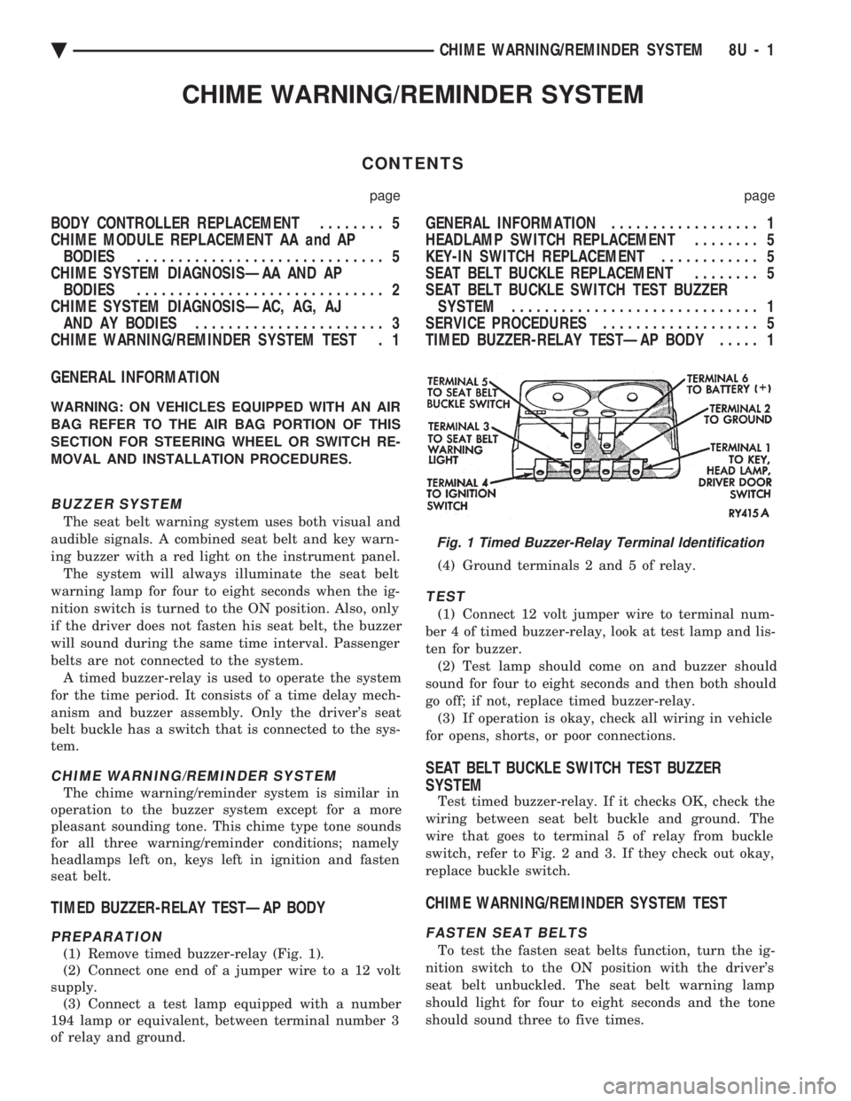
(1) Remove timed buzzer-relay (Fig. 1).
(2) Connect one end of a jumper wire to a 12 volt
supply. (3) Connect a test lamp equipped with a number
194 lamp or equivalent, between terminal number 3
of relay and ground. (4) Ground terminals 2 and 5 of relay.
TEST
(1) Connect 12 volt jumper wire to terminal num-
ber 4 of timed buzzer-relay, look at test lamp and lis-
ten for buzzer. (2) Test lamp should come on and buzzer should
sound for four to eight seconds and then both should
go off; if not, replace timed buzzer-relay. (3) If operation is okay, check all wiring in vehicle
for opens, shorts, or poor connections.
SEAT BELT BUCKLE SWITCH TEST BUZZER
SYSTEM
Test timed buzzer-relay. If it checks OK, check the
wiring between seat belt buckle and ground. The
wire that goes to terminal 5 of relay from buckle
switch, refer to Fig. 2 and 3. If they check out okay,
replace buckle switch.
CHIME WARNING/REMINDER SYSTEM TEST
FASTEN SEAT BELTS
To test the fasten seat belts function, turn the ig-
nition switch to the ON position with the driver's
seat belt unbuckled. The seat belt warning lamp
should light for four to eight seconds and the tone
should sound three to five times.
Fig. 1 Timed Buzzer-Relay Terminal Identification
Ä CHIME WARNING/REMINDER SYSTEM 8U - 1
Page 751 of 2438
GENERAL INFORMATION
CONTENTS
page page
CIRCUIT IDENTIFICATION ................. 3
COMPONENT IDENTIFICATION ............. 3
CONNECTORS ........................... 4
FUSIBLE LINKS ......................... 4
HARNESS REPAIR ....................... 4
LOCATING A SYSTEM .................... 3 SECONDARY IGNITION WIRING
............ 1
SPLICE LOCATIONS ...................... 3
SYMBOLS, FUSES AND RELAYS ........... 7
TROUBLESHOOTING WIRING PROBLEMS .... 4
WIRE CODE IDENTIFICATION .............. 2
WIRING DIAGRAM SHEETS AND INDEXES . . . 1
The wiring diagrams contain the latest information
at the time of publication. Throughout this group ref-
erences may be made to a particular vehicle by letter
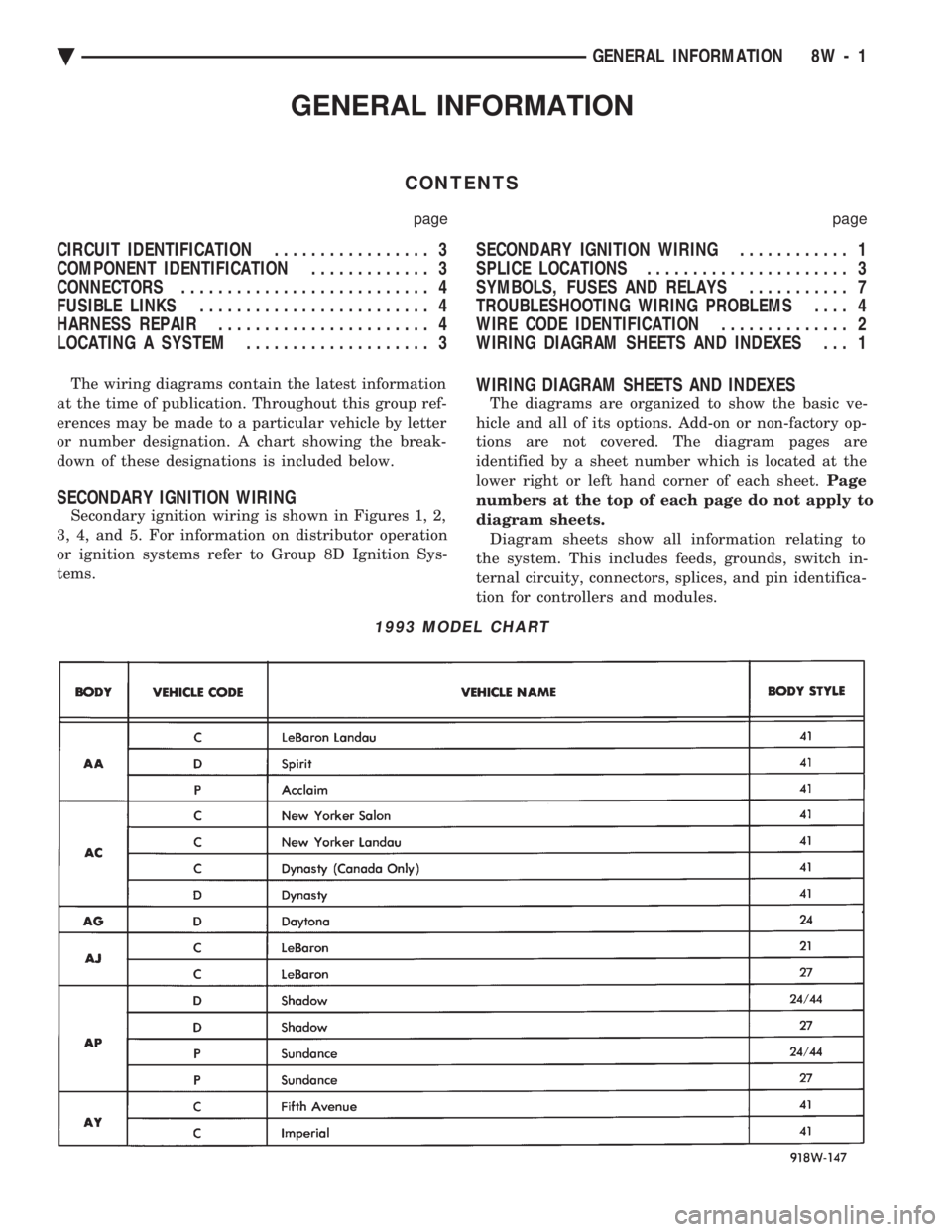
or number designation. A chart showing the break-
down of these designations is included below.
SECONDARY IGNITION WIRING
Secondary ignition wiring is shown in Figures 1, 2,
3, 4, and 5. For information on distributor operation
or ignition systems refer to Group 8D Ignition Sys-
tems.
WIRING DIAGRAM SHEETS AND INDEXES
The diagrams are organized to show the basic ve-
hicle and all of its options. Add-on or non-factory op-
tions are not covered. The diagram pages are
identified by a sheet number which is located at the
lower right or left hand corner of each sheet. Page
numbers at the top of each page do not apply to
diagram sheets. Diagram sheets show all information relating to
the system. This includes feeds, grounds, switch in-
ternal circuity, connectors, splices, and pin identifica-
tion for controllers and modules.
1993 MODEL CHART
Ä GENERAL INFORMATION 8W - 1
Page 757 of 2438

(14) Center the heat shrink tubing over the joint
and heat using a heat gun. Heat the joint until the
tubing is tightly sealed and sealant comes out of both
ends of the tubing. (15) Insert the repaired wire into the connector.
(16) Install the connector locking wedge and recon-
nect the connector to its mating half. (17) Re-tape the wire harness starting 1-1/2 inches
behind the connector and 2 inches past the repair. (18) Connect battery and test all affected systems.
SYMBOLS, FUSES AND RELAYS
Various symbols are used throughout the wiring
diagrams. These symbols can be identified by refer-
ring to the symbol identification chart (Fig. 15). For fuse block, relay bank, or power distribution
center information refer to the fuse charts and relay
bank section.
CAUTION: When replacing a blown fuse it is impor-
tant to replace it with a fuse having the correct am-
perage rating. The use of a fuse with a rating other
than indicated may result in an electrical overload.
If a proper rated fuse continues to blow, it indicates
a problem that should be corrected.
Ä GENERAL INFORMATION 8W - 7