Page 343 of 1216
7Luooo5ENGINE
-Front Case, Oil Pump and Silent Shaft9-59SERVICE POINTS OF DISASSEMBLY
Nom&
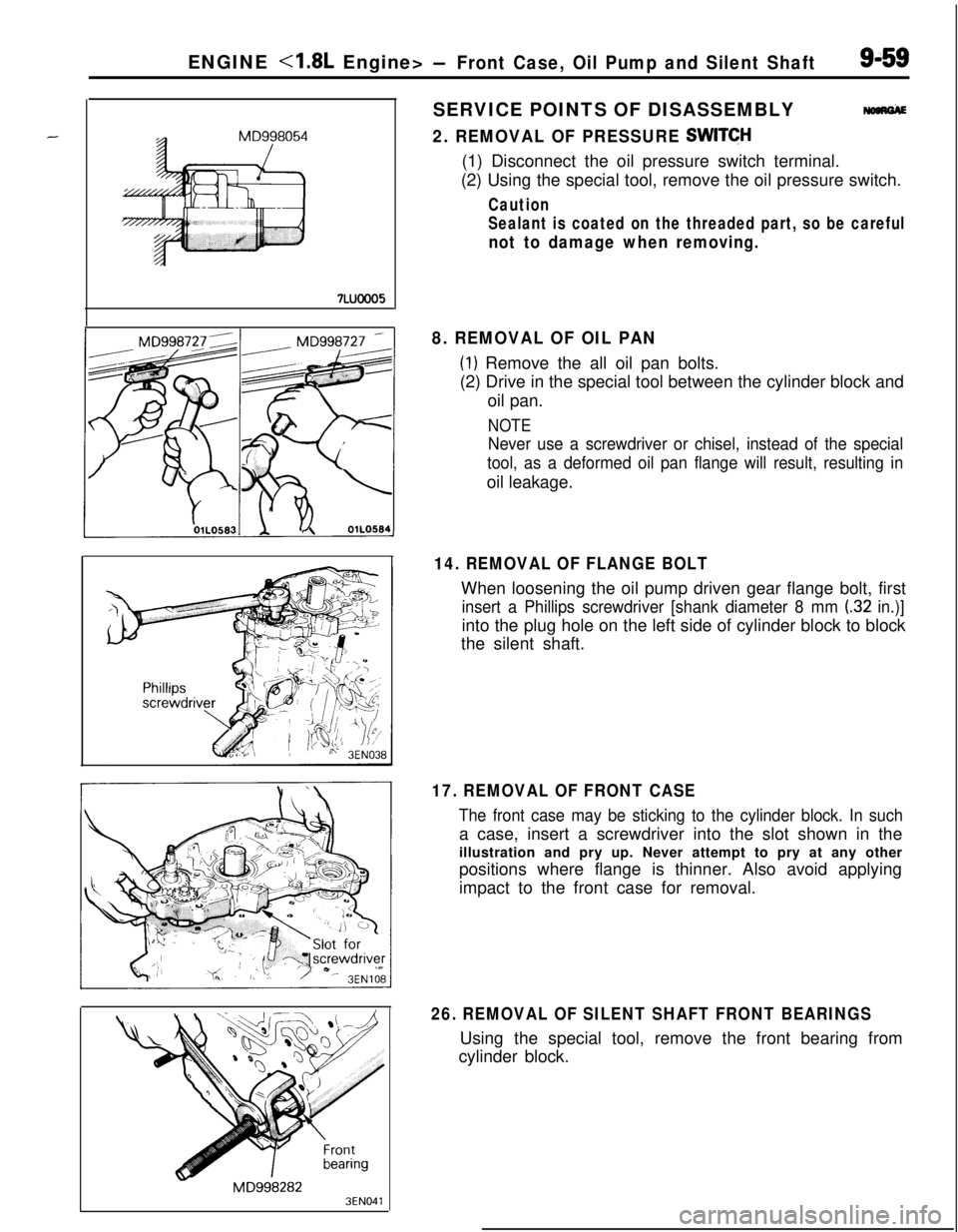
2. REMOVAL OF PRESSURE SWITCH(1) Disconnect the oil pressure switch terminal.
(2) Using the special tool, remove the oil pressure switch.
Caution
Sealant is coated on the threaded part, so be careful
not to damage when removing.
MD9982823EN041
8. REMOVAL OF OIL PAN
(1) Remove the all oil pan bolts.
(2) Drive in the special tool between the cylinder block and
oil pan.
NOTE
Never use a screwdriver or chisel, instead of the special
tool, as a deformed oil pan flange will result, resulting inoil leakage.
14. REMOVAL OF FLANGE BOLTWhen loosening the oil pump driven gear flange bolt, first
insert a Phillips screwdriver [shank diameter 8 mm (32 in.)]into the plug hole on the left side of cylinder block to block
the silent shaft.
17. REMOVAL OF FRONT CASE
The front case may be sticking to the cylinder block. In sucha case, insert a screwdriver into the slot shown in the
illustration and pry up. Never attempt to pry at any other
positions where flange is thinner. Also avoid applying
impact to the front case for removal.
26. REMOVAL OF SILENT SHAFT FRONT BEARINGSUsing the special tool, remove the front bearing from
cylinder block.
Page 346 of 1216
9-62ENGINE -4.8L Engine> -Front Case, Oil Pump and Silent Shaft
OIL RELIEF PLUNGER(1) Check that the relief plunger slides smoothly.
(2) Check the relief spring for breakage.
3EN044J
MD998280
3EN270
0M D998304
SERVICE POINTS OF REASSEMBLYNOBRHAF
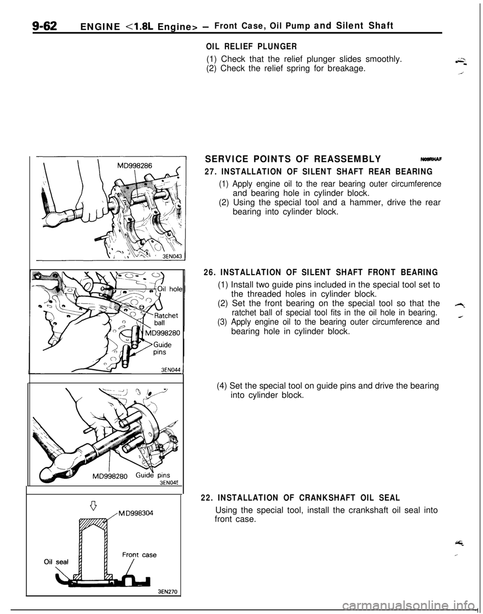
27. INSTALLATION OF SILENT SHAFT REAR BEARING
(1) Apply engine oil to the rear bearing outer circumferenceand bearing hole in cylinder block.
(2) Using the special tool and a hammer, drive the rear
bearing into cylinder block.
26. INSTALLATION OF SILENT SHAFT FRONT BEARING(1) Install two guide pins included in the special tool set to
the threaded holes in cylinder block.
(2) Set the front bearing on the special tool so that the
ratchet ball of special tool fits in the oil hole in bearing.
(3) Apply engine oil to the bearing outer circumference andbearing hole in cylinder block.
(4) Set the special tool on guide pins and drive the bearing
into cylinder block.
22. INSTALLATION OF CRANKSHAFT OIL SEALUsing the special tool, install the crankshaft oil seal into
front case.
Page 349 of 1216
ENGINE <1.8L Engine> - Piston and Connecting Rod9-65
PISTON AND CONNECTING ROD
S--DISASSEMBLY AND REASSEMBLYMaTEA
Disassembly steps
l 4Inspection of connecting rod big end side
clearance1. Nut
+e I)+ 2. Connecting rod cap
3. Cpnnecting rod bearing11. Piston12. Connecting rod
l *4. Piston and connecting rod assembly5. Connecting rod bearing6. Bolt
++I)+ 7. No. 1 piston ring+e l +8. No. 2 piston ringl * 9. Oil ring10. Piston pin
NOTE(1) Reverse the disassembly procedures to reassemble.
(2) 4e : Refer to “Service Points of Disassembly”.
(3) l + : Refer to “Service Points of Reassembly”.
3EN275
Page 350 of 1216
9-66ENGINE <1.8L Engine> - Piston and Connecting Rod
DENOSC
\J5EN05;%Press down withpiston%
Piston ring
End gap6EN037SERVICE POINTS OF
DlSASSEMB&Y
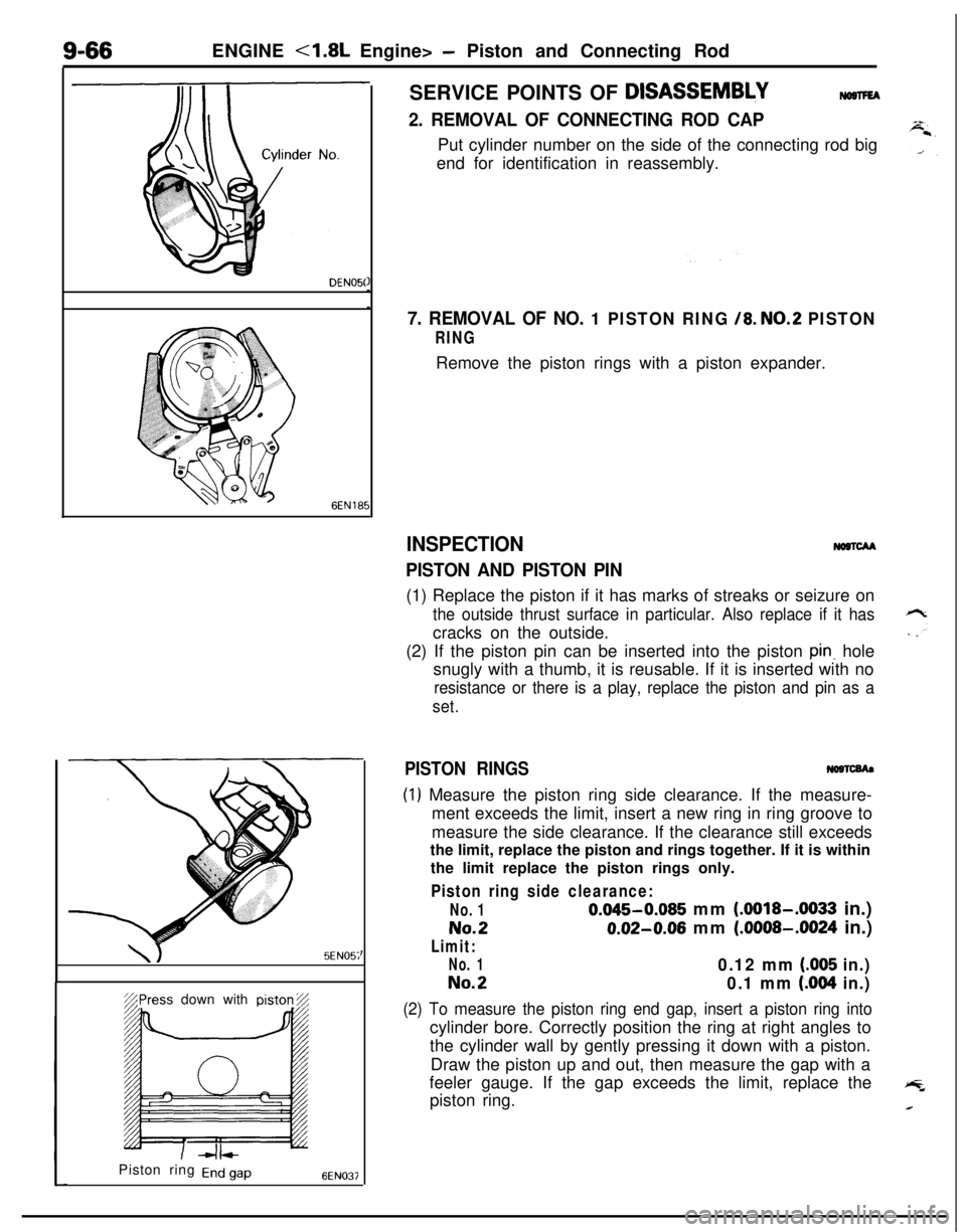
2. REMOVAL OF CONNECTING ROD CAPPut cylinder number on the side of the connecting rod big
end for identification in reassembly.
7. REMOVAL OF NO. 1 PISTON RING /8. NO.2 PISTON
RINGRemove the piston rings with a piston expander.
INSPECTION
PISTON AND PISTON PIN
NoncM(1) Replace the piston if it has marks of streaks or seizure on
the outside thrust surface in particular. Also replace if it hascracks on the outside.
(2) If the piston pin can be inserted into the piston
pink hole
snugly with a thumb, it is reusable. If it is inserted with no
resistance or there is a play, replace the piston and pin as a
set.
PISTON RINGS
(1) Measure the piston ring side clearance. If the measure-
ment exceeds the limit, insert a new ring in ring groove to
measure the side clearance. If the clearance still exceeds
the limit, replace the piston and rings together. If it is within
the limit replace the piston rings only.
Piston ring side clearance:
No. 10.045-0.085 mm (.0018-.0033 in.)
No.20.02-0.06 mm (.0008-.0024 in.)
Limit:
No. 10.12 mm (.005 in.)
No.20.1 mm (.004 in.)
(2) To measure the piston ring end gap, insert a piston ring intocylinder bore. Correctly position the ring at right angles to
the cylinder wall by gently pressing it down with a piston.
Draw the piston up and out, then measure the gap with a
feeler gauge. If the gap exceeds the limit, replace the
piston ring.
Page 351 of 1216
ENGINE <1.8L Engine>- Piston and Connecting Rod9-67
Piston ring end gap:
Standard dimension
No. 10.30-0.45 mm (.0118-.0177 in.)
No.20.20-0.35 mm (.0079-.0138 in.)
Limit0.8 mm LO31in.)
Oil ring side rail:
Standard dimension0.2-0.7 mm (.008-.028 in.)
Limit1.0 mm (.039 in.)When replacing the ring only without correcting the
cylinder bore, check the gap with the ring positioned at a
lower part of cylinder that is less worn.
When replacing a ring, be sure to use a ring of the same
size.
Piston ring service size and mark:
STDNone0.25 mm
(.OlO in.) O.S. 25
0.50 mm
(020 in.) O.S. 50
0.75 mm
(030 in.) O.S. 75
1.00 mm (039 in.) B.S.100
CONNECTION RODSNOSTCCA
(1) Replace the connecting rod if it has damage on thrust faces
at either end. Also replace the connecting rod that has ridgewear or severely rough surface on the inside diameter of
the small end.
When using a new connecting rod, the cylinder number
should be stamped in two places, on the cap and on the
rod.(2) Using a connecting rod aligner, check the rod for bend and
twist. If the measured value is close to the limit, correct therod using a press. Any connecting rod that has been
severely bent or distorted should be replaced.
Bend of connecting rod:
0.05/100 mm (.0020/3.937 in.) or less
Twist of connecting rod:
O.l/lOO mm (.004/3.937 in.) or less
SERVICE POINTS OF REASSEMBLYNOSTGEA
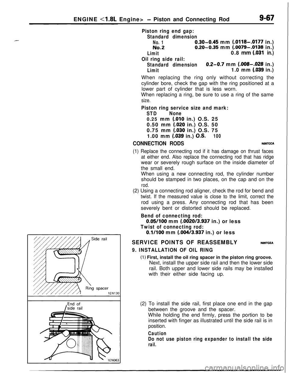
9. INSTALLATION OF OIL RING
(1) First, install the oil ring spacer in the piston ring groove.
Next, install the upper side rail and then the lower side
rail. Both upper and lower side rails may be installed
with their either side facing up.
(2) To install the side rail, first place one end in the gap
between the groove and the spacer.
While holding the end firmly, press the portion to be
inserted with finger as illustrated until the side rail is in
position.
Caution
Do not use piston ring expander to install the side
rail.
Page 353 of 1216
ENGINE <1.8L Engine> -Crankshaft, Flywheel and Drive PlateS-69
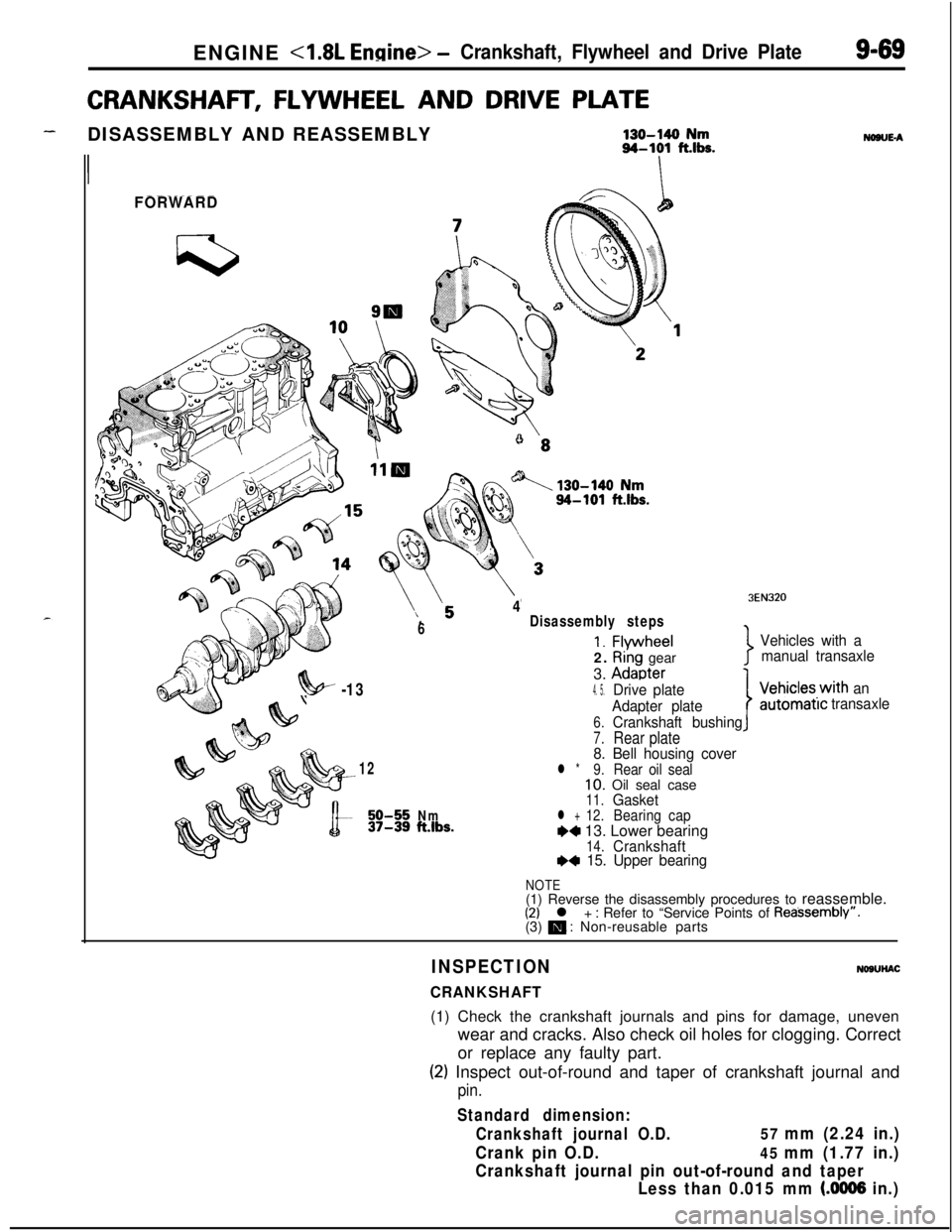
CRANKSHAFT, FLYWHEEL AND DRIVE PLATE
-DISASSEMBLY AND REASSEMBLY130-140 Nm94-101 fths.
II
FORWARD
6
4Disassembly steps
1. Flvwheel2.
Ri’ng gear
3.
Adaoter
NONE-A
3EN320
Vehicles with a
manual transaxle
7
?!w -134. 5.Drive plate
Adapter plate
6.Crankshaft bushing
7.Rear plate8. Bell housing cover12l *9.Rear oil seal10. Oil seal case11.Gasket50-55Nm12.37-39ft.lbs.l +BearingcapW 13. Lower bearing14.CrankshaftI)* 15. Upper bearing
IVehicles.with an
automatrctransaxle
NOTE(1) Reverse the disassembly procedures to reassemble.
(2) l + : Refer to “Service Points of Reassembly”.
(3) m : Non-reusable parts
INSPECTION
CRANKSHAFT
NOSUHAC(1) Check the crankshaft journals and pins for damage, uneven
wear and cracks. Also check oil holes for clogging. Correct
or replace any faulty part.
(2) Inspect out-of-round and taper of crankshaft journal and
pin.
Standard dimension:
Crankshaft journal O.D.
57 mm (2.24 in.)
Crank pin O.D.
45 mm (1.77 in.)
Crankshaft journal pin out-of-round and taper
Less than 0.015 mm
(.0006 in.)
Page 355 of 1216
ENGINE - Crankshaft, Flwvheel and Drive Plate9-71
3EN30’lrrow mark toward
cap No,
I
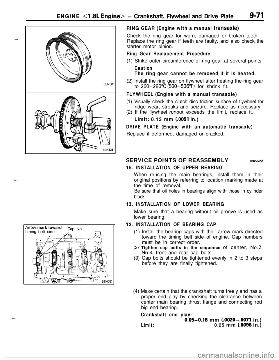
RING GEAR (Engine with a manual transaxle)Check the ring gear for worn, damaged or broken teeth.
Replace the ring gear if teeth are faulty, and also check the
starter motor pinion.
Ring Gear Replacement Procedure(1) Strike outer circumference of ring gear at several points.
Caution
The ring gear cannot be removed if it is heated.(2) Install the ring gear on flywheel after heating the ring gear
to
260-280°C (500-536°F) for shrink fit.
FLYWHEEL (Engine with a manual transaxle)
(1) Visually check the clutch disc friction surface of flywheel forridge wear, streaks and seizure. Replace as necessary.
(2) If the flywheel
runout exceeds the limit, replace it.
Limit: 0.13 mm (0051 in.)
DRIVE PLATE (Engine with an automatic transaxle)Replace if deformed, damaged or cracked.
SERVICE POINTS OF REASSEMBLY
NOSUDAA
15. INSTALLATION OF UPPER BEARINGWhen reusing the main bearings, install them in their
original positions by referring to location marking made at
the time of removal.
Be sure that oil holes in bearings align with those in cylinder
block.
13. INSTALLATION OF LOWER BEARINGMake sure that a bearing without oil groove is used as
lower bearing.
12. INSTALLATION OF BEARING CAP(1) Install the bearing caps with their arrow mark directed
toward the timing belt side of engine. Cap numbers
must be in correct order.(2) Tighten cap bolts in the sequence of center,
No.2,
No.4. front and rear cap bolts.
(3) Cap bolts should be tightened evenly in 2 to 3 steps
before they are finally tightened.
(4) Make certain that the crankshaft turns freely and has a
proper end play by checking the clearance between
center main bearing thrust flange and connecting rod
big end bearing.
Crankshaft end play:
0.05-0.18 mm (.0020-.0071 in.)
Limit:0.25 mm (.0098 in.)
Page 358 of 1216
9-74ENGINE <2.0L DOHC Engine>- Service Adjustment Procedures
ENGINE <2.0L DOHC Engine>
SERVICE ADJUSTMENT PROCEDURES pi
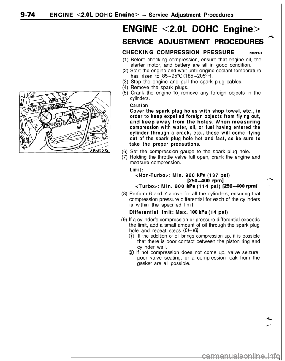
CHECKING COMPRESSION PRESSURENOSFFAH(1) Before checking compression, ensure that engine oil, the
starter motor, and battery are all in good condition.
(2) Start the engine and wait until engine coolant temperature
has risen to
85-95°C (185-205°F).
(3) Stop the engine and pull the spark plug cables.
(4) Remove the spark plugs.
(5) Crank the engine
to. remove any foreign objects in the
cylinders.
Caution
Cover the spark plug holes with shop towel, etc., in
order to keep expelled foreign objects from flying out,and keep away from the holes. When measuring
compression with water, oil, or fuel having entered the
cylinder through a crack, etc., these will come flying
out of the spark plug hole hot and fast, so be sure to
take the proper precautions.(6) Set the compression gauge to the spark plug hole.
(7) Holding the throttle valve full open, crank the engine and
measure compression.
Limit:
: Min. 960 kPa (137 psi)
[250-400 rpm]6: Min. 800
kPa (114 psi) [250-400 rpml-(8) Perform 6 and 7 above for all the cylinders, ensuring that
compression pressure differential for each of the cylinders
is within the specified limit.
Differential limit: Max. 100 kPa (14 psi)(9) If a cylinder’s compression or pressure differential exceeds
the limit, add a small amount of oil through the spark plug
hole and repeat steps (6)-(8).
@If the addition of oil brings compression up, it is possiblethat there is poor contact between the piston ring and
cylinder wall.
@ If not compression does not come up, valve seizure,
poor valve seating, or a compression leak from the
gasket are all possible.‘I