1991 MITSUBISHI ECLIPSE service
[x] Cancel search: servicePage 293 of 1216

ENGINE - SpecificationsItems
Valve stem to valve guide clearance
Intake
Exhaust
Valve guide
Lengthmm (in.)
Intake
Exhaust
Service size
mm (in.)mm (in.)Standard Value
0.03-0.06 (.0012-.0024)
0.05-0.09 (.0020-.0035)44 (1.73)
48 (1.89)
0.05
(.002), 0.25 (.OlO),
0.50
i.020) oversizeLimit
0.10
f.004)0.15
i.006)Valve seat
Width of seat contactmm (in.)
Seat angle
Valve spring
Free lengthmm (in.)
Load
N (Ibs.)
Out of squarness
Cylinder block
Cylinder boremm (in.)
ZIut-of;yundness and taper of cylinder bore
Cylinder block heightmm (in.)
Flatness of gasket surfacemm (in.)qight silent shaft
Front journal diametermm (in.)
Rear journal diametermm (in.)
Oil clearancemm (in.)
Front journal
Rear journal
-eft silent shaft
Front journal diametermm (in.)
Rear journal diametermm (in.)
Oil clearancemm (in.)
Front journal
Rear journal
‘istonO.D.mm (in.)
Clearance (Piston to cylinder)mm (in.)
0.9-l .3 (.0354-.0512)
44”-44.549.2
(1.937)48.2 (1.898)
274.6 (62) at installed height
Less than 2”4”
80.6 (3.173)
Less than 0.01
(.0004)285.2
(11.228)Less than 0.05
(.0020)0.1 (.0039)38.959-38.975
(1.5338- 1.5344)
35.951-35.967
(1.4154- 1.4160)
0.030-0.061(.0012-.0024)
0.050-0.091(.0020- .0036)
18.467- 18.480(.7270- .7276)
35.951-35.967(1.4154-1.4160)
0.020-0.054 (.0008-.0021)
0.050-0.091 (.0020-.0036)80.6
(3.173)
0.01-0.03 (.0004-.0012)
Page 295 of 1216

ENGINE - SDecifications9-11
.-ems
Ring groove widthmm (in.)
No. 1No. 2
Oil
Service sizemm (in.)Standard ValueLimit1.52- 1.54 (.0598-.0606)
1.51-l .53 (.0594-.0602)
4.015-4.045 (.1581-.1593)0.25
(.OlO), 0.50 (.020),0.75 (.030), 1.00 (.039)oversize
ston ring
Side clearancemm (in.)
No. 1No. 2
End gapmm (in.)
No. 1No. 2
Oil ring side railmm (in.)
Service sizemm (in.)
0.045-0.085 (.0018-.0033)0.12 (.005)
0.02-0.06 (.0008-.0024)0.1 (.004)
0.30-0.45 LO1 188.0177)0.8 (.031)
0.20-0.35 (.0079-0.138)0.8 i.031)
0.20-0.70 (.0079-.0276)1.0 (.039)0.25
(.OlO), 0.50 (.020).0.75 (.030), 1.00 LO391oversize
lnnecting rod
Bendmm (in.)
Twistmm (in.)
Connecting rod
bigmKdi,;; crankshaft
side clearance
Piston pin press-in loadN (Ibs.)
xrnecting rod bearing
Oil clearancemm (in.)
Service sizemm (in.)0.05 or less per 100
(.0020 or less per 3.937)
0.1 or less per 100
LOO39 or less per 3.937)
0.10-0.25 (.0039-.0098)0.4 (.016)
5,000- 15,500 (l ,l OO-3,300)
0.02-0.05 (.0008-.0020)0.1 (.004)0.25
(.OlO), 0.50 (.020),0.75 (.030) undersize.ankshaft main bearing
Oil clearancemm (in.)
Service sizemm (in.)
0.02-0.05 (.0008-.0020)0.25
(.OlO), 0.50 i.0201,
0.75 l.030) undersize
ankshaft
Pin O.D.mm (in.)45 (1.77)
Journal O.D.mm (in.)57 (2.24)
Out-of-roundness of journal and pinmm (in.)Less than
0.015 (.OOOS)Taper of journal and pinmm (in.)Less than
0.005 (.0002)tnd playmm (in.)
0.05-0.18 (.0020-.0070)0.4 (.016)
Page 298 of 1216

9-14ENGINE - SpecificationsItems
Oversize rework of valve guide hole
(both intake and exhaust)mm (in.)
0.05
(.002) O.S.0.25
(.OlO) O.S.
0.50
(.020) 0,s.Standard Value
12.050-12.068(.4744-.4751)
12.250-12.268(.4823-.4830)
12.500-12.518
(.4921-.4928)Limit
,’Camshaft
Cam heightmm (in.)
Intake
Exhaust
Journal O.D.mm (in.)
25.951-25.970(1.0217-1.0224)Bearing oil clearancemm (in.)
0.05-0.09 (.0020-.0035)End playmm (in.)
0.1-0.2 (.004-,008)Valve
Valve lengthmm (in.)
Intake
109.5 (4.311)
Exhaust
109.7 (4.319)
Stem O.D.mm (in.)
Intake
6.565-6.580(.2585-.2591)Exhaust
6.530-6.550
(.2571-.2579)Face angle
45"-45.5"Thickness of valve head (Margin)
mm (in.)
Intake
1.0
(.040)0.7 (.028)Exhaust
1.5
(.059)1.0 (.040)Jalve stem to valve guide clearance
mm (in.)
Intake
0.02-0.047 (.0008-.0019)0.10 (.004)Exhaust
0.05-0.085 (.0020-.0033)0.15 (.006)Jalve guide
Length
mm (in.)
Intake
45.5 (1.791)
Exhaust
50.5 (1.988)
Service size
mm (in.)
0.05
(.002), 0.25 (.OlO),0.50 (.020) oversize
/alve seat
Width of seat contact
mm (in.)
0.9-1.3 (.035-.051)Seat angle
44"-44.5"Service size
mm (in.)
0.3
(.012), 0.6 (.024)oversize
Page 299 of 1216

ENGINE - Specifications9-15ItemsStandard ValueLimit
Valve spring
Free lengthmm (in.)48.3
(1.902)47.3 (1.862)
Load
N (Ibs.)300 (66) at installed height
Out of squarnessLess than 1.5”4”
Cylinder block
Cylinder boremm (in.)85.00 (3.3465)
FIu-o$xrndness and taper of cylinder boreLess than 0.01 (0004)Flatness of gasket surfacemm (in.)Less than 0.05
(.0020)0.1 (.0040)Right silent shaft
Front journal diameter
mm (in.)
41.959-41.975(1.6519-1.6526)
Rear journal diameter
mm (in.)
40.951-40.967(1.6122-1.6129)
Oil clearancemm (in.)
Front journal
0.020-0.061 (.0008-.0024)Rear journal
0.050-0.091 (.0020-.0036)Left silent shaft
Front journal diameter
mm (in.)
18.467- 18.480(.7270-.7276)Rear journal diameter
mm (in.)
40.959-40.975
(1.6126-1.6132)Oil clearancemm (in.)
Front journal
0.020-0.054 (.0008-.0021)Rear journal
0.042-0.083 (.0017-.0033)Piston
O.D.
mm (in.)85.00 (3.3465)
CnlIr;;y (Piston to cylinder)(Non-Turbo) 0.02-0.04 (.0008-.0016)(Turbo)
0.03-0.05 (.0012-.0020)Ring groove width
mm (in.)
No. 11.22-l .24 (.0480-.0488)
No.21.52- 1.54 (.0598-.0606)Oil
3.01-3.03 (.1185-.1193)Service sizemm (in.)0.25
(.OlO), 0.50 (.020),0.75
(.030), 1 .oo i.039)oversize‘iston ring
Side clearancemm (in.)
No.1. No.2End gapmm (in.)
No. 1No. 2
Oil ring side railmm (in.)
Service sizemm (in.)
0.03-0.07 (.0012-.0028)
0.25-0.45 (.0098-.0177)
0.35-0.50 (.0138-.0197)
0.20-0.70 (.0079-.0276)0.25
(.OlO), 0.50 (.020),0.75 (030). 1.00 i.039)oversize0.1
(.004)0.8
(.031)0.8
(.031)1.0
(.040)
Page 308 of 1216

9-24ENGINE - Service Adjustment Procedures
ENGINE 4.8L Engine>
SERVICE ADJUSTMENT PROCEDURES -
CHECKING COMPRESSION PRESSURENOSFFAI
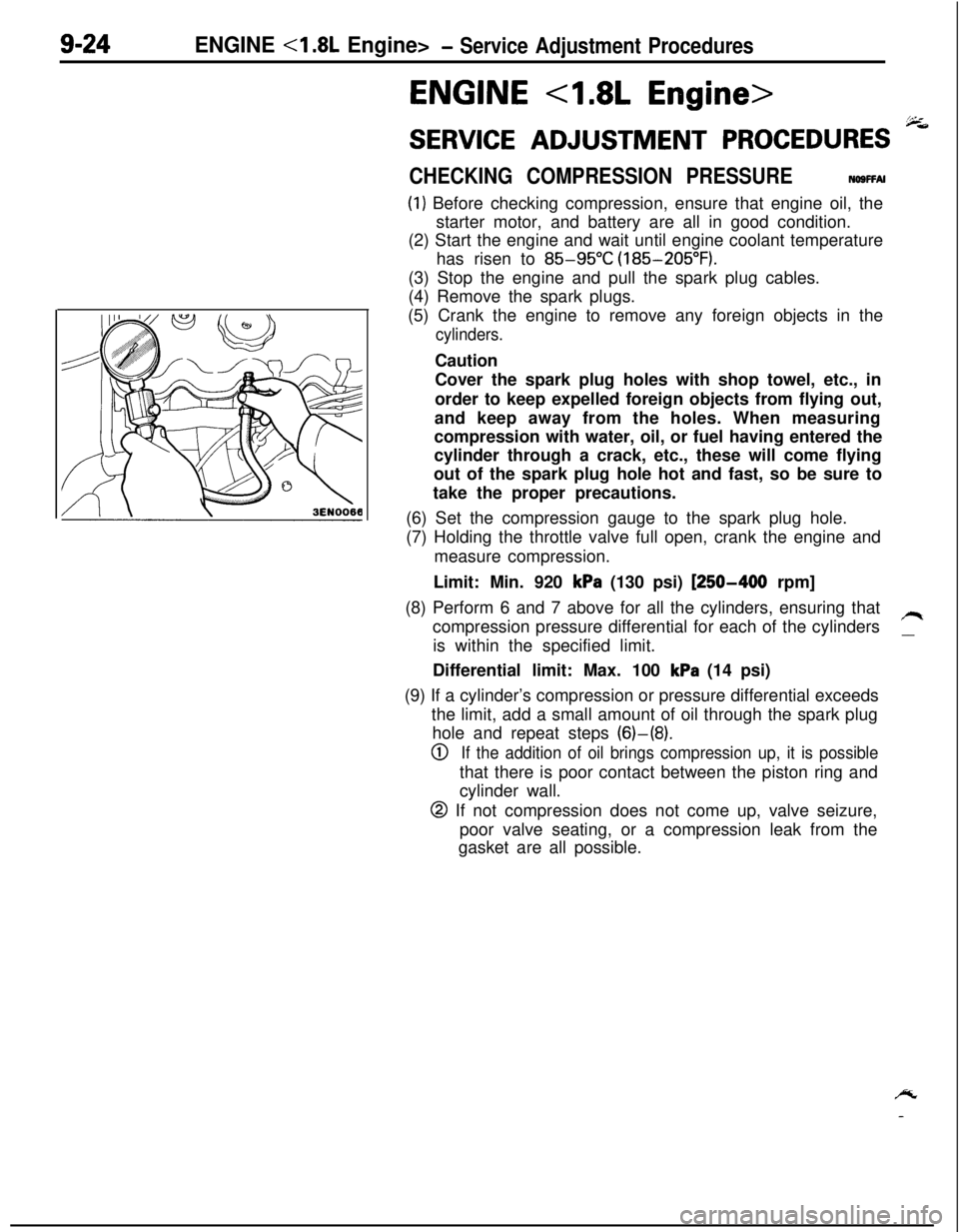
(1) Before checking compression, ensure that engine oil, the
starter motor, and battery are all in good condition.
(2) Start the engine and wait until engine coolant temperature
has risen to
85-95°C (185-205°F).
(3) Stop the engine and pull the spark plug cables.
(4) Remove the spark plugs.
(5) Crank the engine to remove any foreign objects in the
cylinders.Caution
Cover the spark plug holes with shop towel, etc., in
order to keep expelled foreign objects from flying out,
and keep away from the holes. When measuring
compression with water, oil, or fuel having entered the
cylinder through a crack, etc., these will come flying
out of the spark plug hole hot and fast, so be sure to
take the proper precautions.
(6) Set the compression gauge to the spark plug hole.
(7) Holding the throttle valve full open, crank the engine and
measure compression.
Limit: Min. 920
kPa (130 psi) [250-400 rpm]
(8) Perform 6 and 7 above for all the cylinders, ensuring that
compression pressure differential for each of the cylinders
/Iis within the specified limit.
__Differential limit: Max. 100
kPa (14 psi)
(9) If a cylinder’s compression or pressure differential exceeds
the limit, add a small amount of oil through the spark plug
hole and repeat steps (6)-(8).
0If the addition of oil brings compression up, it is possiblethat there is poor contact between the piston ring and
cylinder wall.
@ If not compression does not come up, valve seizure,
poor valve seating, or a compression leak from the
gasket are all possible.
/y
-
Page 309 of 1216

ENGINE <1.8L Engine>- Service Adjustment Procedures9-25
MANIFOLD VACUUM INSPECTION(1) Before inspection and adjustment, put the vehicle
in=following state.
l Engine coolant temperature:
85-95°C (185-205°F)
l Lights, electric, cooling fan, and accessories: OFF
lTransaxle: Neutral
(N or P for vehicles with an automa-
tic transaxle)
l Steering wheel: Neutral position
(2) Check that the idling revolution speed is normal.
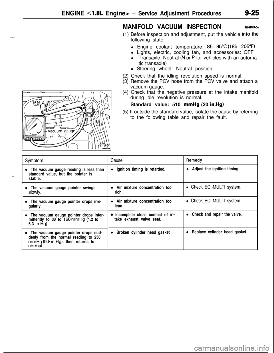
(3) Remove the PCV hose from the PCV valve and attach a
vacuum gauge.
(4) Check that the negative pressure at the intake manifold
during idle revolution is normal.
Standard value: 510 mmHg (20
in.Hg)(5) If outside the standard value, isolate the cause by referring
to the following table and repair the fault.
SymptomCauseRemedy
l The vacuum gauge reading is less thanl Ignition timing is retarded.l Adjust the ignition timing.
standard value, but the pointer is
-stable.
l The vacuum gauge pointer swingsl Air mixture concentration too
slowly.rich.
l Check ECI-MULTI system.l The vacuum gauge pointer drops irre-
gularly.
l The vacuum gauge pointer drops inter-
mittently to 30 to
160 mmHg (1.2 to
6.3 in.Hg).l The vacuum gauge pointer drops sud-
denly from the normal reading to 250rronnrt$,(9.8 rn.Hg), then returns tol Air mixture concentration too
lean.
l Check ECI-MULTI system.0 Incomplete close contact of in-
take exhaust valve seat.l Check and repair the valve.
l Broken cylinder head gasketl Replace cylinder head gasket.
Page 310 of 1216

9-26ENGINE <1.8L Engine> -Service Adjustment Procedures
TIMING BELT TENSION ADJUSTMENTNOSFGBCThere are two access holes provided in the timing belt front
lower cover. The two access holes can be used to readjust thetension of the timing belt, by following the procedures
described below, without the necessity of removing the timing
belt front lower cover. Note, however, that timing belt “B”,
which drives the right silent shaft, cannot be adjusted unless
the cover is removed.
(1) Turn the steering wheel all the way to the left.
(2) Remove the left side undercover panel.
NOTEThis work is done so that the crankshaft can be turned.
(3) Place a piece of wood against the engine oil pan and jack
(4)
:tmove the engine mounting bracket.
(5) Remove the timging belt front upper cover.
(6) Remove the four spark plugs.
(7) Turn the crankshaft clockwise and check the timing belt
condition.
OlAOOBlTiming mark
(on upper under cover)
Timing mark
(on camshaft sprocket)
OlR0153cover
‘I!i
OlA0082
01 A0083(8) Turn the crankshaft clockwise and align the timing marks.
(9) Remove the air conditioner drive belt and the alternator
drive belt.
(10)Remove the access cover (two places). There are easily
removed by inserting a screwdriver into the slots indicated
by the raised arrows in the timing belt cover and twisting.
(1l)lnser-t a socket wrench [a 14 mm (.55 in.) box wrench]
through the hole in the access cover and loosen the timing
belt tension bolt and nut.
Caution
The timing belt tension bolt and nut need only be
loosened
180”-200”. Any further loosening might re-
sult in their falling off inside the timing belt cover.
Page 311 of 1216

ENGINE <1.8L Engine> -Service Adjustment Procedures9-27
I.
Timing mark(on upper under cover)Timing belt
Timing mark
A(on camshaft
sprocket)OlR0154
3EN076
3EN07;-
(12)Turn the crankshaft clockwise by two teeth of the camshaft
sprocket.
(13)First tighten the timing belt tensioner installation bolt (on
the lower side), and then tighten the tensioner spacer
(upper side).Caution
Be sure to tighten the bolt (lower side) first. If the
tensioner spacer of pivot side is tightened first, the
tensioner will rotate with it and belt tension may
become loose.
(14)lnstall the access cover. The access cover may be easily
installed by passing the hooks between the guides and
sliding it in.
(15)lnstall the air conditioner drive belt and alternator drive belt
and adjust the slack.
(16)lnstalI the timing belt front upper cover.
(17)lnstall the engine mounting bracket.
(18)lnstalI the spark plugs.
(19)lnstall the left side undercover panel.
LASH ADJUSTERS CHECKNO9FEABaO
If an abnormal noise is heard from the lash adjusters check asfollows.
(I) After warming up the engine, stop it.
(2) While installed to the cylinder head, press the part of rockerfeel very hard if the lash adjuster condition is normal.
(3) If, when pressed, it easily descends all the way downward,
(4) If there.is a spongy feeling when pressed, air is probably
cause is probably an insufficient amount of engine oil, or
damage to the oil screen and/or screen gasket.
(adding oil or repair), warm up the engine and drive at low
speed for a short time. Then, after stopping the engine andthis procedure a few times to bleed out the air from the oil.