Page 312 of 1216
9-28ENGINE <1.8L Engine> - Engine Mounting
ENGINE MOUNTING
IEMOVAL AND INSTALLATION
NOB8A-APost-installation Operation
50-65 Nm*Lower the Engine36-47 ft.lbs.
30-40 Nm
22-26 ft.lbs.Removal steps
1. Pressure hose (power steering)
2. Engine mount bracket and body
connection bolt
3. Engine mount bracket
e+ 4. Mounting stopper
NOTE(1) Reverse the removal procedures to reinstall.(2) +* : Refer to “Service Points of Installation”
INSPECTIONNOOQCANOl Check each insulator for cracks or damage.
l Check each bracket for deformation or damage.
MountingSERVICE POINTS OF INSTALLATION4. INSTALLATION OF MOUNTING STOPPER
Install the mounting stopper of the engine mount bracket
so that the arrow faces the center part of the engine.
Arrow
OiA0004
Page 314 of 1216
50-65 Nm*36-47 ft.lbs.*
9-30ENGINE - Engine Roll Stopper
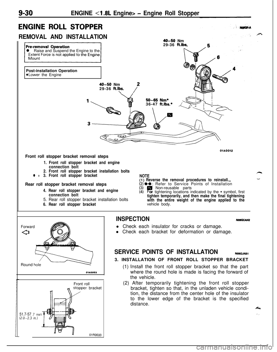
ENGINE ROLL STOPPER
REMOVAL AND INSTALLATION40-50 Nm
29-36 ft.lbs.
l Raise and Suspend the Engine to the
Post-installation Operation
*Lower the Engine
40-50 Nm
29-36 ft.lbs.\/*01A0012
Front roll stopper bracket removal steps1. Front roll stopper bracket and engine
connection bolt
2. Front roll stopper bracket installation bolts
l +3. Front roll stopper bracket
Rear roll stopper bracket removal steps4. Rear roll stopper bracket and engine
connection bolt
5. Rear roll stopper bracket installation bolts6. Rear roll stopper bracketNOTE
(1) Reverse the removal procedures to reinstall.,,
I;/ I)+ : Refer to Service Points of Installation
Non-reusable parts
(4)Por tightening locations indicated by the * symbol, first
tighten temporarily, and then make the final tightening
with the entire weight of the engine applied to the
vehicle body.
ForwardRound
h&Front roll
51.7-5712.0-2.3.7 mnin.)
bracket
INSPECTIONNosGcAH2l Check each insulator for cracks or damage.
l Check each bracket for deformation or damage.
SERVICE POINTS OF INSTALLATIONNOSGJASl3. INSTALLATION OF FRONT ROLL STOPPER BRACKET
(1)
Install the front roll stopper bracket so that the part
where the round hole is made is facing the forward of
the vehicle.
(2) After temporarily tightening the front roll stopper
bracket, tighten so that, in the unladen vehicle condi-
tion, the distance from the center hole of the insulator
to the lower edge of the bracket is the specified
distance.
Page 315 of 1216
ENGINE <1.8L Engine> - Engine Assembly9-31
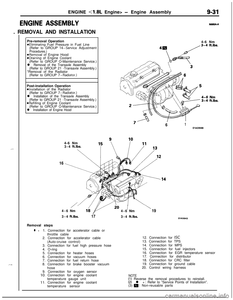
ENGINE ASSEMBLY
. REMOVAL AND INSTALLATION
N69SA-APre-removal Operation
@Eliminating Fuel Pressure in Fuel Line
(Refer to GROUP 14-Service AdjustmentProcedures.)@Removal of Engine HoodeDraining of Engine Coolant
(Refer to GROUP O-Maintenance Service.)
l Removal of the Transaxle Assembly(Refer to GROUP 21 -Transaxle Assembly.)
*Removal of the Radiator
(Refer to GROUP 7-Radiator.)
Post-installation Operation
@Installation of the Radiator
(Refer to GROUP 7-Radiator.)
l Installation of the Transaxle Assembly(Refer to GROUP 21 -Transaxle Assembly.)
@Refilling of Engine Coolant
(Refer to GROUP O-Maintenance Service.)
l Installation of Engine Hood4-6 Nm
“7
/61OlA05664-6 Nm
3-4
ft.lbs.
\
16
/io1\4-6Nm164-6Nm193-4ft.lbs.
173-4ft.lbs.OlA0643Removal steps
l +1. Connection for accelerator cable or
throttle cable
2. Connection for accelerator cable
(Auto-cruise control)
3. Connection for fuel high pressure hose
4. O-ring
5. Connection for heater hoses
6. Connection for vacuum hoses
7. Connection for fuel return hose
8. Connection for brake booster vacuum
hose
9. Connection for oxygen sensor
10. Connection for engine coolant
temperature gauge unit
11. Connection for engine coolant
temperature sensor12. Connection for
ISC13. Connection for TPS
14. Connection for MPS
15. Connection for fuel injectors
16. Connection for EGR temperature sensor
17. Connection for distributor
18. Connection for CRC filter
19. Connection for ground cable
20. Control wiring harness
NOTE(1) Reverse the removal procedures to reinstall.(2) l + : Refer to “Service Points of Installation”.
(3) m : Non-reusable parts
Page 316 of 1216
9-32ENGINE <1.8L Engine> - Engine Assembly35-45 Nm
25-33
ft.lbs.
25 31\5$M35 Nm
36-47 ft.lbs.
OlAO56429-36
ft.lbs.
3&40 Nm
22-29 ft.lbs.
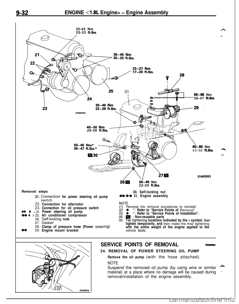
Removal steps
21.
zztTtion for power steering oil pump30. Self-locking nut4e +4 31. Engine assembly
+e l + 24.*I)l 425.
26.27.
28.
4+29.
\60-80 Nm
43-58 ft.lbs.
OlAO563Connection for alternator
Connection for oil pressure switch
Power steering oil pump
Air conditioner compressor
palffz,cklng nuts
Clamp of pressure hose (Power
steelEngine mount bracket
ITEReverse the removal procedures to reinstall.
l *
: Refer to “Service Points of Removal”.
l * : Refer to “Service Points of Installation”.
P; Non-reusable parts
or ttghtening locations indicated by the * symbol, firs1tighten temporarily, and then make the final tightening
with the entire weight of the engine applied to the
vehicle
body.
t
SERVICE POINTS OF REMOVALNogs6SC24. REMOVAL OF POWER STEERING OIL PUMP
Remove the oil pump (with the hose attached).
NOTESuspend the removed oil pump (by using wire or similar
material) at a place where no damage will be caused duringremoval/installation of the engine assembly.
Page 317 of 1216
ENGINE <1.8L Engine> - Engine Assemblv9-33
c
!
OlAO582
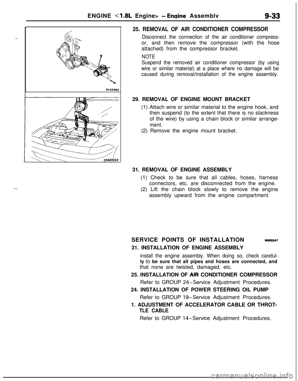
25. REMOVAL OF AIR CONDITIONER COMPRESSOR
Disconnect the connection of the air conditioner compress-or, and then remove the compressor (with the hose
attached) from the compressor bracket.
NOTE
Suspend the removed air conditioner compressor (by using
wire or similar material) at a place where no damage will be
caused during removal/installation of the engine assembly.29. REMOVAL OF ENGINE MOUNT BRACKET
(1) Attach wire or similar material to the engine hook, and
then suspend (to the extent that there is no slackness
of the wire) by using a chain block or similar arrange-
ment.(2) Remove the engine mount bracket.
31. REMOVAL OF ENGINE ASSEMBLY
(1) Check to be sure that all cables, hoses, harness
connectors, etc. are disconnected from the engine.
(2) Lift the chain block slowly to remove the engine
assembly upward from the engine compartment.
SERVICE POINTS OF INSTALLATION
NOSSDAT31. INSTALLATION OF ENGINE ASSEMBLY
install the engine assembly. When doing so, check careful-ly to be sure that all pipes and hoses are connected, and
that none are twisted, damaged, etc.
25. INSTALLATION OF AIR CONDITIONER COMPRESSOR
Refer to GROUP
24-Service Adjustment Procedures.
24. INSTALLATION OF POWER STEERING OIL PUMP
Refer to GROUP
19-Service Adjustment Procedures.
1. ADJUSTMENT OF ACCELERATOR CABLE OR THROT-
TLE CABLERefer to GROUP
14-Service Adjustment Procedures.
Page 318 of 1216
-
c/
(Refer to GROUP O-Maintenance
9-34ENGINE <1.8L Engine>- Oil Pan and Oil Screen
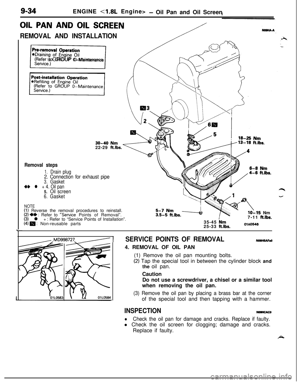
OIL PAN AND OIL SCREEN
REMOVAL AND INSTALLATION
30-40 Nm22-29 ftlbs.
Removal steps
1.Drain plug
2. Connection for exhaust pipe
3.Gasket
** l + 4. Oil pan5.Oil screen
6.Gasket
NOTE(1) Reverse the removal procedures to reinstall.(2) +e : Refer to “Service Points of Removal”.(3) l + : Refer to “Service Points of Installation”.(4) m : Non-reusable parts
lo-15 Nm
7-11 ftlbs.35-45 Nm25-33 ftlbs.OlAO546
,,Mq998727_/ 1SERVICE POINTS OF REMOVALNOSHBAFaO4. REMOVAL OF OIL PAN
(1) Remove the oil pan mounting bolts.
(2) Tap the special tool in between the cylinder block and
the oil pan.
Caution
Do not use a screwdriver, a chisel or a similar tool
when removing the oil pan.
(3) Remove the oil pan by placing a brass bar at the cornerof the special tool and then tapping with a hammer.
INSPECTIONNOHCACO
lCheck the oil pan for damage and cracks. Replace if faulty.l Check the oil screen for clogging; damage and cracks.
Replace if faulty.
Page 319 of 1216
ENGINE - Oil Pan and Oil Screen9-35
SERVICE POINTS OF INSTALLATIONIYW~DU)4. INSTALLATION OF OIL PAN
(1)Use a wire brush or other tool to scrape clean all gasketsurfaces of the cylinder block and oil pan so that all
loose material is removed.
(2) Gasket surfaces must be free of oil and dirt.
(3) Apply the specified sealant around the gasket surface
of oil pan as specified in illustration.
Specified sealant: MITSUBISHI GENUINE PART
No.
MD9971 10 or equivalent
NOTEThe sealant should be applied in a continuous bead
approximately 4 mm
(.I6 in.) in diameter.
(4) Assemble oil pan to cylinder block within 15 minutes
after applying the sealant.
Caution
After installing the oil pan, wait at least 30 minutes
before starting the engine.
Page 320 of 1216
9-36ENGINE - Cylinder Head Gasket
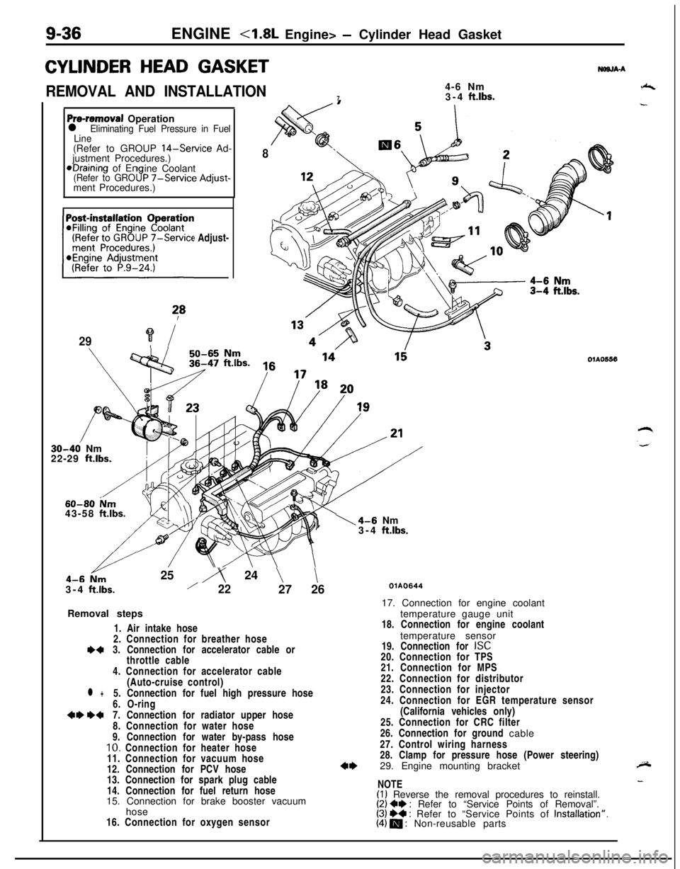
CYLINDER HEAD GASKET
REMOVAL AND INSTALLATION4-6 Nm
73-4 ft.lbs.
NWJA-A
Pre-removal Operationl Eliminating Fuel Pressure in Fuel
Line(Refer to GROUP
14-Service Ad-
justment Procedures.)*Draining of En
ine Coolant
(Refer to GRO9P -/-Service Adjust-ment Procedures.)
(Refer to GROUP
7-Service Adjust-~~~~~~~n
?*
29?i
8
30-46 Nm
22-29 ft.lbs.
60-80 ium43-58 ftlbs.25
iy 24 \\3-4
ftlbs./2227 26
Removal steps
1. Air intake hose
2. Connection for breather hose
I)43. Connection for accelerator cable or
throttle cable
4. Connection for accelerator cable
(Auto-cruise control)
l +5. Connection for fuel high pressure hose
6. O-ring
+e W7. Connection for radiator upper hose
8. Connection for water hose
9. Connection for water by-pass hose
10. Connection for heater hose
11. Connection for vacuum hose
12. Connection for PCV hose
13. Connection for spark plug cable
14. Connection for fuel return hose
15. Connection for brake booster vacuum
hose
16. Connection for oxygen sensor
1\4-6 Nm
3-4 ftlbs.
OlAO556
QlAO64417. Connection for engine coolant
temperature gauge unit
18. Connection for engine coolant
temperature sensor
19. Connection for
ISC20. Connection for TPS
21. Connection for MPS
22. Connection for distributor
23. Connection for injector
24. Connection for EGR temperature sensor
(California vehicles only)
25. Connection for CRC filter
26. Connection for ground cable
27. Control wiring harness
28. Clamp for pressure hose (Power steering)
29. Engine mounting bracket
NOTE
(I) Reverse the removal procedures to reinstall.(2) Ce : Refer to “Service Points of Removal”.(3) ++ : Refer to “Service Points of Installation”.(4) m : Non-reusable parts