Page 260 of 1216
7-12COOLING - Radiator
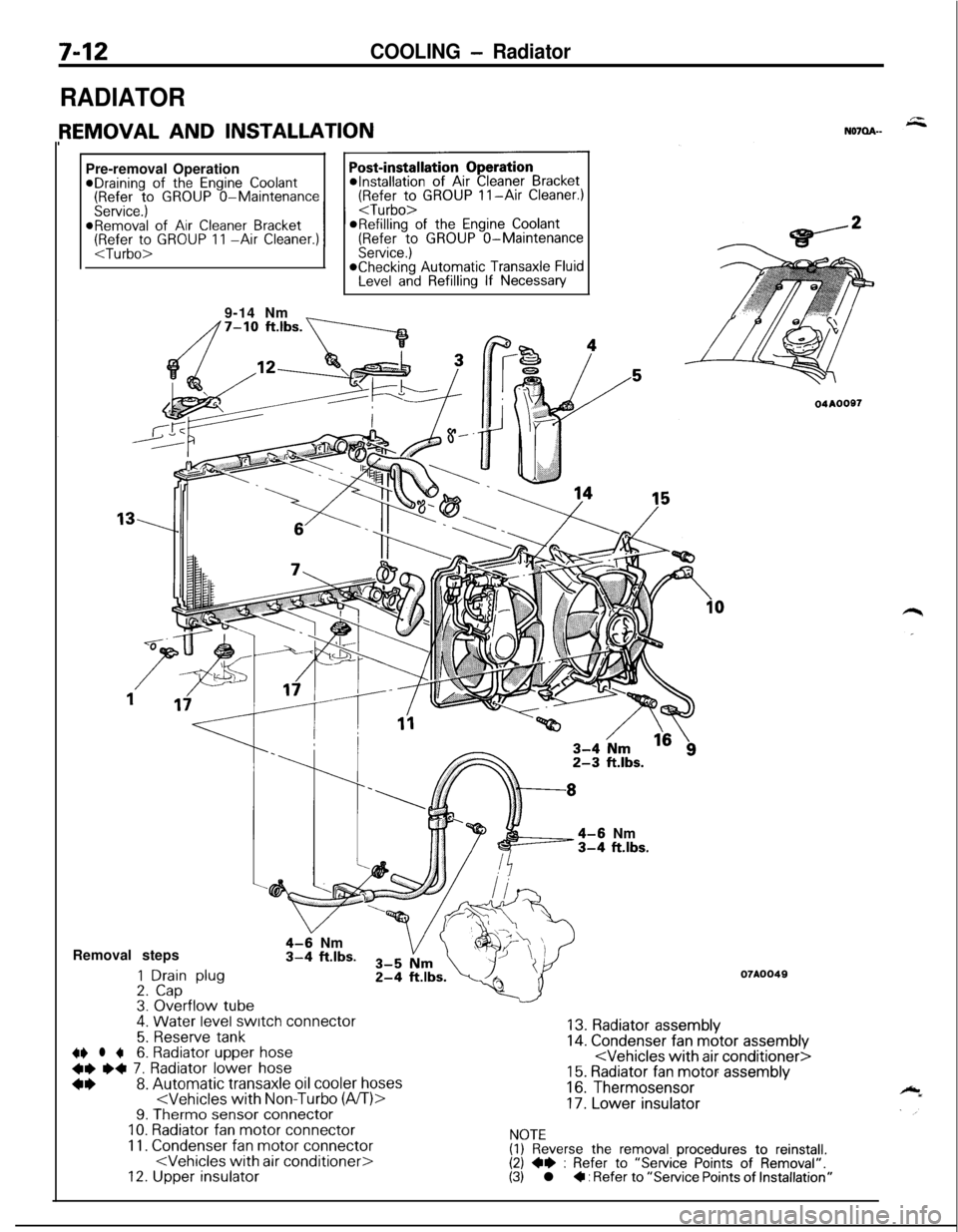
RADIATORPre-removal Operation
@Draining of the Engine Coolant(Refer to GROUP O-Maintenance(Refer to GROUP II-Air Cleaner.)
Service.)
I I
@Removal of Air Cleaner BracketORefilling of the Engine Coolant(Refer to GROUP 11 -Air Cleaner.)(Refer to GROUP O-MaintenanceService.)*Checking Automatic Transaxle FluidLevel and Refilling If Necessary
9-14 Nm
_
4-6 Nm3-4 ft.lbs.Removal steps
1 Drain plug2. Cap3. Overflow tube.
4-9 Nm3-4 ft.lbs.
4. Water level switch connector
5. Reserve tank~~ l +6. Radiator upper hose
+e e+ 7. Radiator lower hose
*I)8. Automatic transaxle oil cooler hoses9. Therm0 sensor connectorIO. Radiator fan motor connector
11. Condenser fan motor connector12. Upper insulator
04AOOS7
07A0049
13. Radiator assembly14. Condenser fan motor assembly15. Radiator fan motor assembly
16. Thermosensor
17. Lower insulator
NOTE(1) Reverse the removal procedures to reinstall.(2) +e : Refer to “Service Points of Removal”.(3) l + : Refer to “Service Points of Installation”
Page 261 of 1216
COOLING- Radiator7-13Mating
marks
04A0020
SERVICE POINTS OF REMOVALN07QBAH
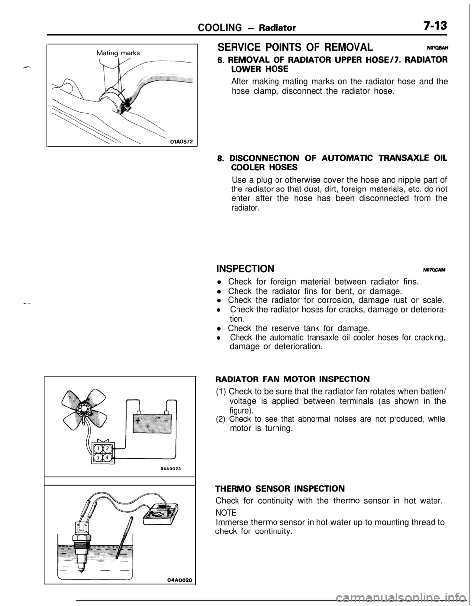
6. REMOVAL OF RADIATOR UPPER HOSE/7. RADIATOR
LOWER HOSEAfter making mating marks on the radiator hose and the
hose clamp, disconnect the radiator hose.
8. DISCONNECTION OF AUTOMATIC TRANSAXLE OIL
COOLER HOSESUse a plug or otherwise cover the hose and nipple part of
the radiator so that dust, dirt, foreign materials, etc. do not
enter after the hose has been disconnected from the
radiator.
INSPECTIONNo7OcAMl Check for foreign material between radiator fins.
l Check the radiator fins for bent, or damage.
l Check the radiator for corrosion, damage rust or scale.
lCheck the radiator hoses for cracks, damage or deteriora-
tion.l Check the reserve tank for damage.
lCheck the automatic transaxle oil cooler hoses for cracking,damage or deterioration.
RADIATOR FAN MOTOR INSPECTION(1) Check to be sure that the radiator fan rotates when batten/
voltage is applied between terminals (as shown in the
figure).
(2) Check to see that abnormal noises are not produced, whilemotor is turning.
THERM0 SENSOR INSPECTIONCheck for continuity with the therm0 sensor in hot water.
NOTEImmerse therm0 sensor in hot water up to mounting thread to
check for continuity.
Page 262 of 1216
7-14COOLING - Radiator
A
OFF
ON
h
--- ,
BWatertemperature
16v1100
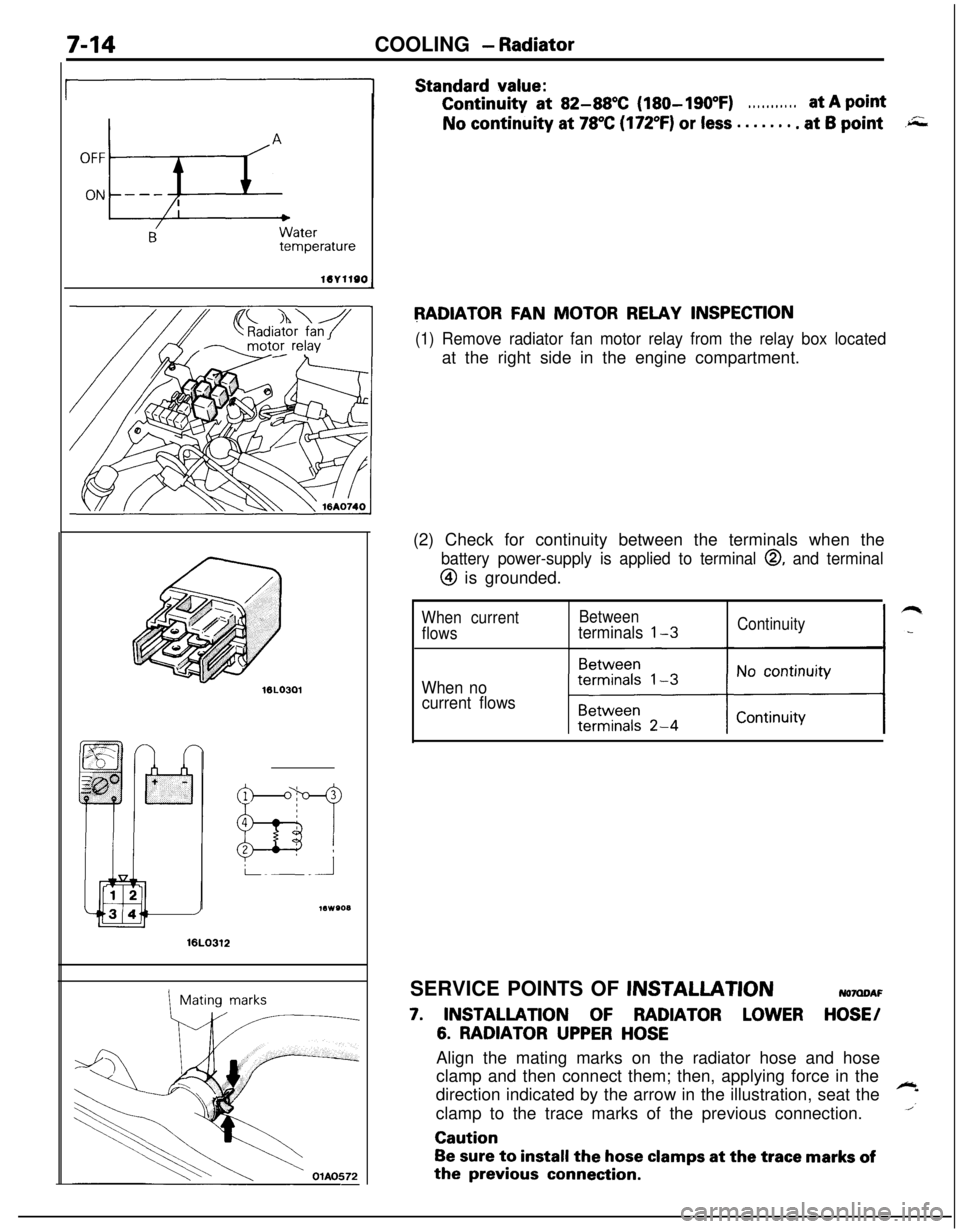
Standard value:Continuity
at 82-88X (180-190°F). . . . . . . . . . .at A pointNo continuity at
78°C (172°F) or less . . . . . . . . at 6 point.r;;;
RADIATOR FAN MOTOR RELAY INSPECTION
(1) Remove radiator fan motor relay from the relay box locatedat the right side in the engine compartment.
16LO312
1Mating marks(2) Check for continuity between the terminals when the
battery power-supply is applied to terminal 0, and terminal
@ is grounded.
When currentBetween
flowsterminals l-3Continuity
When no
current flowsSERVICE POINTS OF
JNSTALLATIONNOMDAF
7. INSTALLATION OF RADIATOR LOWER HOSE/
6. RADIATOR UPPER HOSEAlign the mating marks on the radiator hose and hose
clamp and then connect them; then, applying force in the
direction indicated by the arrow in the illustration, seat the
~
1clamp to the trace marks of the previous connection.Caution
Be sure to install the hose clamps at the trace marks ofthe
previous connection.
Page 263 of 1216
COOLING - Radiator Fan Motor AssemblvIThermostat7-15
RADIATOR FAN MOTOR ASSEMBLYDISASSEMBLY AND REASSEMBLY
04AOO92
NOTTA-
Disassembly steps
1. Fan2. Radiator fan motor
3. Shroud
NOTEReverse the disassembly procedures to reassemble.
THERMOSTATREMOVAL AND INSTALLATION
N07G6-
< 1.8LDOHC
P17-20 Nm
12-14 ft.lbs.
112-14 ftlbs. 1
44Removal steps
m5al51. Cap+e l 42. Connection for radiator upper hose
663. Connection for overflow tube
;. ra;t;er;utlet fitting
l + 6: Thermostat
NOTE
2(I) Reverse the removal procedures to reinstall.(2) ~~ : Refer to “Service Points of Removal”.(3) l 4 : Refer to “Service Points of Installation”.
04Aoo91(4) 19 : Non-reusable parts
Mating marks
Radiator hose
04A009ESERVICE POINTS OF REMOVAL
NO7GCFU
2. DISCONNECTION OF RADIATOR UPPER HOSEAfter making mating marks on the radiator hose and the
hose clamp, disconnect the radiator hose.
Page 264 of 1216
7-16COOLING - Thermostat
INSPECTIONy+w
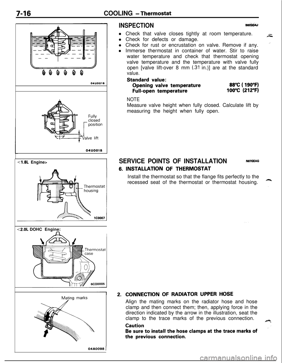
l Check that valve closes tightly at room temperature.
l Check for defects or damage.
l Check for rust or encrustation on valve. Remove if any.
l Immerse thermostat in container of water. Stir to raise
water temperature and check that thermostat opening
valve temperature and the temperature with valve fully
open [valve lift-over 8 mm
(.31 in.)] are at the standard
value.Standard
value:Opening
valve temperature
Full-open temperature
88°C ( 190°F)
100°C (212°F)
Fullyclosedpositionve lift
04UOO18<1.8L Engine><2.0L DOHCEngine:
IMating
marks
NOTEMeasure valve height when fully closed. Calculate lift by
measuring the height when fully open.
SERVICE POINTS OF INSTALLATIONNOlGEAG
6. INSTALLATION OF THERMOSTAT
Install the thermostat so that the flange fits perfectly to the
recessed seat of the thermostat or thermostat housing.
2.CONNECTION OF RADIATOR UPPER HOSEAlign the mating marks on the radiator hose and hose
clamp and then connect them; then, applying force in the
direction indicated by the arrow in the illustration, seat the
clamp to the trace marks of the previous connection.
Caution
Be sure to install the hose clamps at the trace marks ofthe
previous connection.
04A0099 )
Page 265 of 1216
COOLING - Water Pump <1.8L Engine>
WATER PUMP 4.8L Engine>
7-17
- REMOVAL AND INSTALLATION
c.
-_*Draining of
the Engine Coolant(Refer to GROUP O-Maintenance
Post-installation Operation
l installation of the Under Cover@Supplying of the Engine Coolant(Refer to GROUP O-MaintenanceService.)@Engine Adjustment(RR:; to GROUP g-Engine Adjust-
8-10 Nm6-7 ftlbs.
48NOlMB-A
30-40 Nm
22-2g Fbs.
0
60-80 Nm43-58 ft.lbs.5-18
Nm1-13 ft.lbs.18-22 NmRemoval steps13-15 ft.lbs.
1. Clamp part of hoses (Power steering)4+2. Engine mount bracketl +3. Drive belt (Air conditioner)I)+ 4. Drive belt (Power steering)
4+ l + 5. Drive belt
7. Water pump pulleyWater pump pulleyDamper pullevAdapter. ’Crank shaft pulley.
OlAO566
(Powersteering)
6. Tension tx~llev bra&&I\lnTFr--‘--I -‘--‘.--I.VIL(I) Reverse the removal procedures to reinstall.I?\ CI Refer tn “Smvirr rh:-*- -‘ D---./al”,\-, --. I.VIw, .”..-..,u; r”llllb “I “allI”\(3) +4 : Refer to “Service Points nf Instalk_ - .,.__ -. _.._ .-Jion”.
Page 266 of 1216
7-18COOLING - Water Pump <1.8L Engine>
lo-12 Nm7-9 ft.lbs.OlA05813
17
Removal steps
12. Spark plug cable+e l 4 13. Rocker cover14. Rocker cover gasket
l + 15. Semi-circular packing~~ e+ 16. Timing belt front upper coverl
17. Timing belt front lower cover+e l 18. Timing belt19. Crankshaft sprocketl 20. Flange21.
Timing belt B tensionerl I) ~~ 22. Timing belt B23.
Alternator bracel + 24. Water pump25.
Water pump gasketl + 26. O-ring
NUlt(I) Reverse the removal procedures to reinstall.(2) ** : Refer to “Service Points of Removal”.(3) l 4 : Refer to “Service Points of Installation”.(4) m : Non-reusable parts
Page 267 of 1216
COOLING - Water Pump <1.8L Engine>749SERVICE POINTS OF REMOVAL
NO’IMCAG
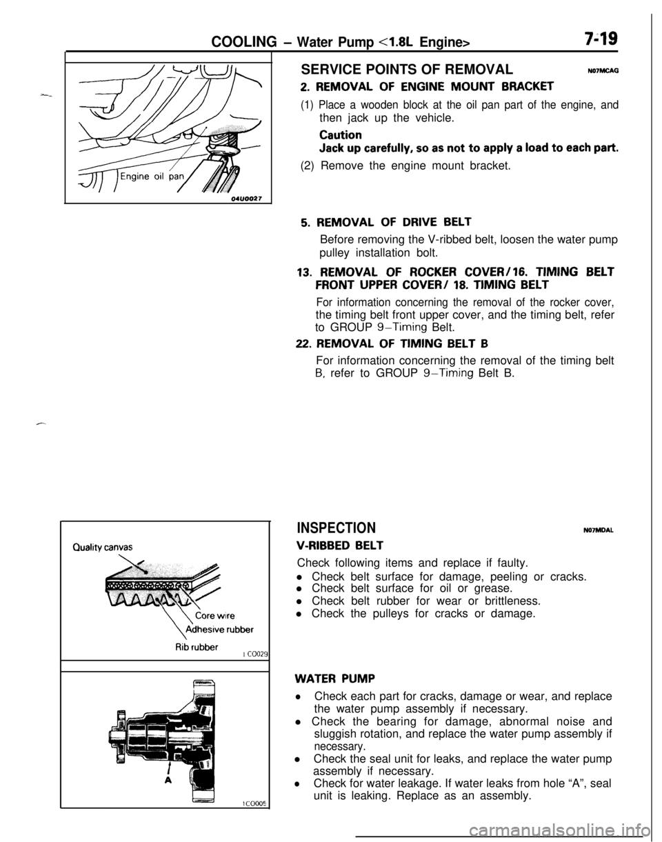
2. REMOVAL OF ENGINE MOUNT BRACKET
(1) Place a wooden block at the oil pan part of the engine, andthen jack up the vehicle.
Caution
Jack up carefully, so as not to apply a load to each part.(2) Remove the engine mount bracket.
\
\
Core wireAdhesive
rubber
Rib rubber1 coo21
5. REMOVAL OF DRIVE BELTBefore removing the V-ribbed belt, loosen the water pump
pulley installation bolt.
13. REMOVAL OF ROCKER COVER/16. TIMING BELT
FRONT UPPER COVER/ 18. TIMING BELT
For information concerning the removal of the rocker cover,the timing belt front upper cover, and the timing belt, refer
to GROUP
g-Timing Belt.
22. REMOVAL OF TIMING BELT BFor information concerning the removal of the timing belt
B, refer to GROUP g-Timing Belt B.
INSPECTIONN07MDAL
V-RIBBED BELTCheck following items and replace if faulty.
l Check belt surface for damage, peeling or cracks.
l Check belt surface for oil or grease.
l Check belt rubber for wear or brittleness.
l Check the pulleys for cracks or damage.
WATER PUMP
lCheck each part for cracks, damage or wear, and replace
the water pump assembly if necessary.
l Check the bearing for damage, abnormal noise and
sluggish rotation, and replace the water pump assembly if
necessary.lCheck the seal unit for leaks, and replace the water pump
assembly if necessary.
lCheck for water leakage. If water leaks from hole “A”, seal
unit is leaking. Replace as an assembly.