Page 247 of 1216
CLUTCH - Clutch Cover and Disc647
08A0038
6CLOO3SERVICE POINTS OF REMOVAL
NO6OSAH
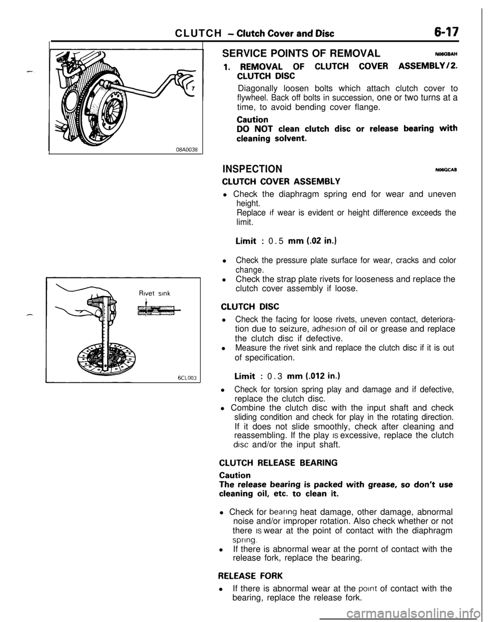
1. REMOVAL OF CLUTCH COVER ASSEMBLY/P.
CLUTCH DISCDiagonally loosen bolts which attach clutch cover to
flywheel. Back off bolts in succession, one or two turns at atime, to avoid bending cover flange.
Caution
DO NOT clean clutch disc or release bearing with
cleaning solvent.
INSPECTIONNlNGCAB
CLUTCH COVER ASSEMBLYl Check the diaphragm spring end for wear and uneven
height.
Replace
If wear is evident or height difference exceeds the
limit.Limit
: 0.5 mm (.02 in.)l
Check the pressure plate surface for wear, cracks and color
change.lCheck the strap plate rivets for looseness and replace the
clutch cover assembly if loose.
CLUTCH DISCl
Check the facing for loose rivets, uneven contact, deteriora-tion due to seizure,
adhesron of oil or grease and replace
the clutch disc if defective.
l
Measure the rivet sink and replace the clutch disc if it is outof specification.Limit
: 0.3 mm (.012 in.)l
Check for torsion spring play and damage and if defective,replace the clutch disc.
l Combine the clutch disc with the input shaft and check
sliding condition and check for play in the rotating direction.If it does not slide smoothly, check after cleaning and
reassembling. If the play IS excessive, replace the clutch
drsc and/or the input shaft.
CLUTCH RELEASE BEARING
Caution
The release bearing is packed with grease, so don’t use
cleaning oil, etc. to clean it.l Check for
beanng heat damage, other damage, abnormal
noise and/or improper rotation. Also check whether or not
there IS wear at the point of contact with the diaphragm
spring.lIf there is abnormal wear at the pornt of contact with the
release fork, replace the bearing.
RELEASE FORKlIf there is abnormal wear at the
pornt of contact with the
bearing, replace the release fork.
Page 248 of 1216
6-18CLUTCH - Clutch Cover and Disc
I6CLO33
Clutch disc
T& assemblyClutch cover
6CLO26
SERVICE POINTS OF INSTALLATIONNWGDAT
5. A,PPLlCATlONOF GREASE TO RELEASE FORKAi&
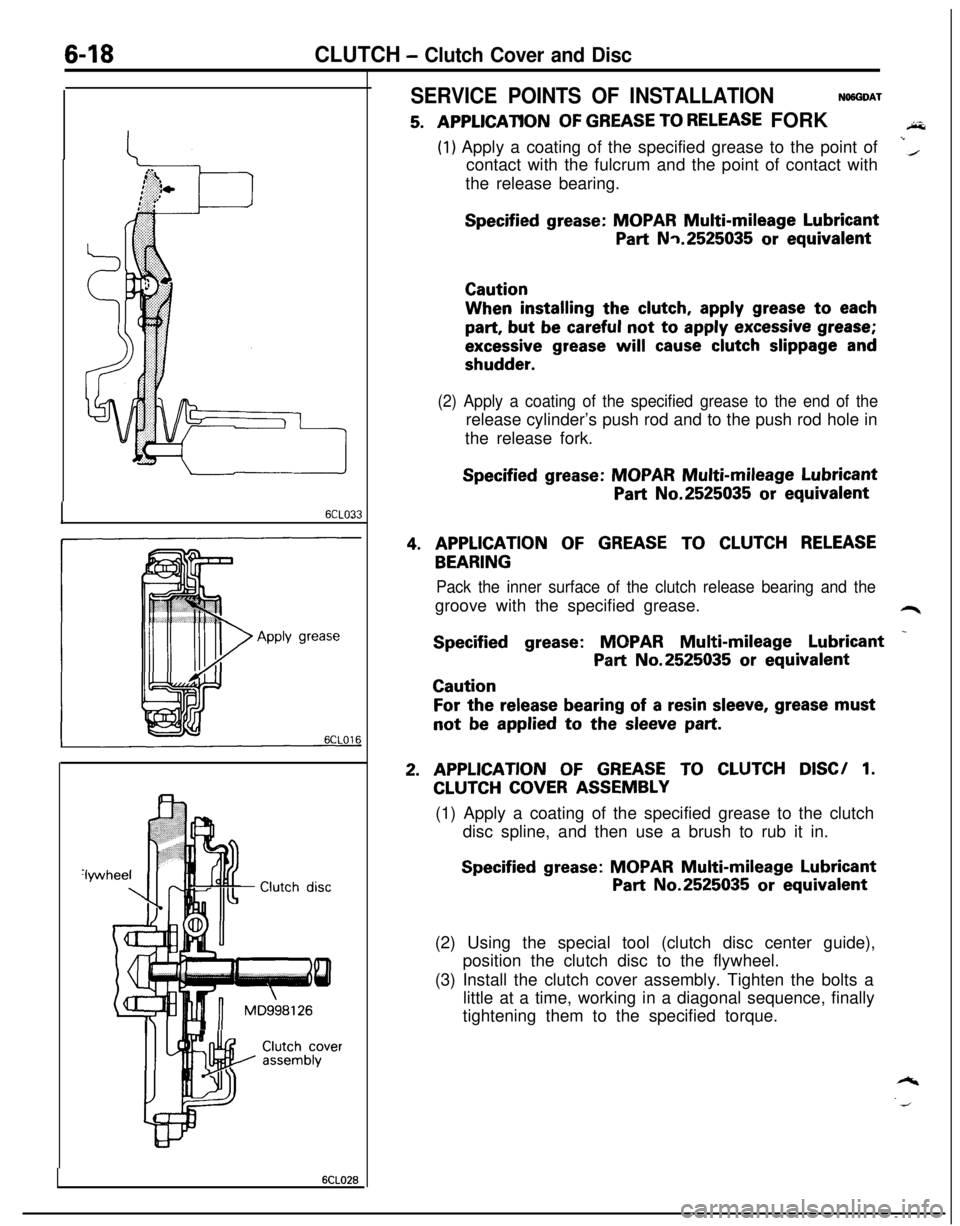
(1) Apply a coating of the specified grease to the point of
contact with the fulcrum and the point of contact withi(the release bearing.
Specified grease: MOPAR Multi-mileage Lubricant
Part Nq.2525035 or equivalentCautionWhen installing the
clutch, apply grease to each
part, but be careful not to apply excessive grease;
excessive grease will cause clutch slippage and
shudder.
(2) Apply a coating of the specified grease to the end of therelease cylinder’s push rod and to the push rod hole in
the release fork.
Specified grease: MOPAR Multi-mileage Lubricant
Part No.2525035 or equivalent
4. APPLICATION OF GREASE TO CLUTCH RELEASE
BEARING
Pack the inner surface of the clutch release bearing and thegroove with the specified grease.
L4r
Specified grease: MOPAR Multi-mileage Lubricant _
Part No.2525035 or equivalentCaution
For the release bearing of a resin sleeve, grease mustnot
be applied to the sleeve part.
2. APPLICATION OF GREASE TO CLUTCH DISC/ 1.
CLUTCH COVER ASSEMBLY
(1) Apply a coating of the specified grease to the clutch
disc spline, and then use a brush to rub it in.
Specified grease: MOPAR Multi-mileage Lubricant
Part No.2525035 or equivalent
(2) Using the special tool (clutch disc center guide),
position the clutch disc to the flywheel.
(3) Install the clutch cover assembly. Tighten the bolts a
little at a time, working in a diagonal sequence, finally
tightening them to the specified torque.
Page 249 of 1216
7-l
COOLING
CONTENTS
ENGINE COOLANT TEMPERATURE GAUGEUNIT,
ENGINE COOLANT TEMPERATURE
SENSOR AND ENGINE COOLANT
TEMPERATURE SWITCH................................34
RADIATOR.......................................................12
RADIATORFANMOTOR ASSEMBLY..........15
SERVICE ADJUSTMENT PROCEDURES.......8
Alternatormater Pump Drive Belt Tension
Adjustment
....................................................9Alternator/Water Pump Drive Belt Tension
Inspection..
....................................................8Cap Pressure Test
.......................................8Engine Coolant Concentration Test
.............8
EngineCoolantLeakCheck........................8Engine Coolant Replacement
.......................8
SPECIFICATIONS.............................................2
GeneralSpecifications..................................2
Lubricant.......................................................4
Sealant..........................................................4Service Specifications
...................................2Torque Specifications
...................................3THERMOSTAT
.................................................15
TROUBLESHOOTING......................................5
Noriseintemperature................................5
Overheat.......................................................5
WATER HOSE AND WATER PIPE
<1.8L Engine>................................................25
WATER HOSE AND WATER PIPE
<2.0LDOHCEngine(Non-Turbo)>.............28
WATER HOSE AND WATER PIPE
<2.0LDOHCEngine(Turbo)>....................31
WATERPUMP<1.8LEngine>.....................17
WATER PUMP <2.0L DOHC Engine>.........21
Page 250 of 1216
7-2COOLING - Specifications
SPECIFICATIONS
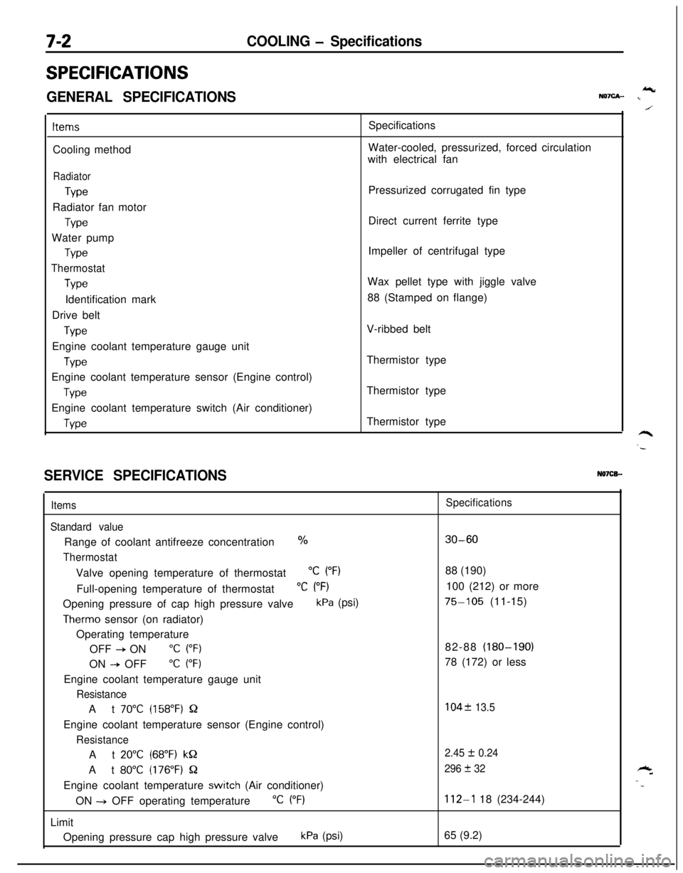
GENERAL SPECIFICATIONSIcNQ7cA- I
ItemsCooling method
Radiator
TypeRadiator fan motor
TypeWater pump
Type
Thermostat
TypeIdentification mark
Drive belt
TypeEngine coolant temperature gauge unit
WeEngine coolant temperature sensor (Engine control)
TypeEngine coolant temperature switch (Air conditioner)
WeSpecifications
Water-cooled, pressurized, forced circulation
with electrical fan
Pressurized corrugated fin type
Direct current ferrite type
Impeller of centrifugal type
Wax pellet type with jiggle valve
88 (Stamped on flange)
V-ribbed belt
Thermistor type
Thermistor type
Thermistor type
SERVICE SPECIFICATIONSN07CB.-
Items
Standard valueRange of coolant antifreeze concentration
%
ThermostatValve opening temperature of thermostat
“C (“F)Full-opening temperature of thermostat
“C (“F)Opening pressure of cap high pressure valve
kPa (psi)
Therm0 sensor (on radiator)
Operating temperature
OFF
+ ON“C (“F)ON
--P OFF“C (“F)Engine coolant temperature gauge unit
ResistanceAt
70°C (158°F) QEngine coolant temperature sensor (Engine control)
ResistanceAt
20°C (68°F) kQAt
80°C (176°F) QEngine coolant temperature
switch (Air conditioner)
ON -+ OFF operating temperature
“C (“F)Limit
Opening pressure cap high pressure valve
kPa (psi)
Specifications
30-6088 (190)
100 (212) or more
75-105 (11-15)
82-88 (180-190)
78 (172) or less
104f 13.5
2.45
I!I 0.24
296
+ 32
112-l 18 (234-244)
65 (9.2)
Page 256 of 1216
7-8COOLING - Service Adjustment Procedures
04DooE
SERVICE ADJUSTMENT PROCEDURESENGINE COOLANT LEAK CHECK
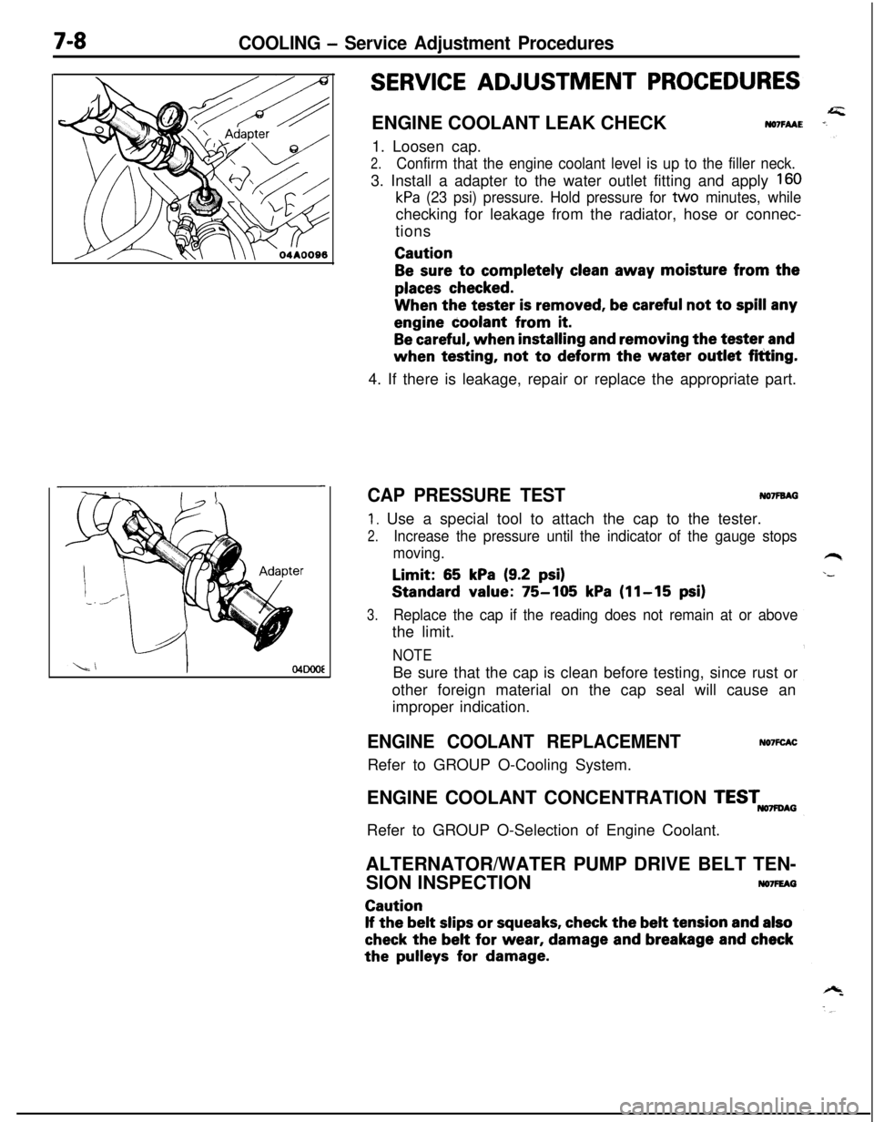
NO7FAAE1. Loosen cap.
2.Confirm that the engine coolant level is up to the filler neck.3. Install a adapter to the water outlet fitting and apply
160
kPa (23 psi) pressure. Hold pressure for tvvo minutes, whilechecking for leakage from the radiator, hose or connec-
tionsCaution
Be sure to completely clean away moisture from the
places checked.When the tester
is removed, be careful not to spill anyengine coolant from
it.
Be careful, when installing and removing the tester andwhen testing, not
to deform the water outlet fitting.
4. If there is leakage, repair or replace the appropriate part.
CAP PRESSURE TESTNO’IFBAG
1. Use a special tool to attach the cap to the tester.
2.Increase the pressure until the indicator of the gauge stops
moving.Limit:
65 kPa (9.2 psi)Standard value:
75-105 kPa (11-15 psi)
3.Replace the cap if the reading does not remain at or abovethe limit.
NOTEBe sure that the cap is clean before testing, since rust or
other foreign material on the cap seal will cause an
improper indication.
ENGINE COOLANT REPLACEMENTRefer to GROUP O-Cooling System.NO’IFCACENGINE COOLANT CONCENTRATION
TESTmAGRefer to GROUP O-Selection of Engine Coolant.
ALTERNATOR/WATER PUMP DRIVE BELT TEN-
SION INSPECTION
NO7FEAGCaution
If the belt slips or squeaks, check the belt tension and also
check the belt for wear, damage and breakage and checkthe
pulleys for damage.
Page 257 of 1216
COOLING - Service Adjustment Procedures7-9Alterhatorpulley
6COOOO9
Spindle
l-
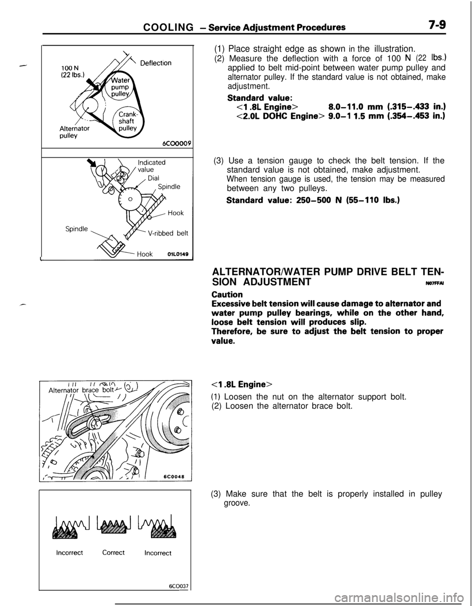
(1) Place straight edge as shown in the illustration.(2) Measure the deflection with a force of 100
N(22lb4applied to belt mid-point between water pump pulley and
alternator pulley. If the standard value is not obtained, make
adjustment.Standard
value:
8.0-11.0 mm (.315-433 in.)
<2.0L DOHC Engine> 9.0-I 1.5 mm (.354-.453 in.)(3) Use a tension gauge to check the belt tension. If the
standard value is not obtained, make adjustment.
When tension gauge is used, the tension may be measuredbetween any two pulleys.Standard
value: 250-500 N (55-110 Ibs.)
IncorrectCorrectIncorrect
6COO37-ALTERNATOR/WATER PUMP DRIVE BELT TEN-
SION ADJUSTMENT
ruo7FFAl
Caution
Excessive belt tension will cause damage to alternator and
water pump pulley bearings, while on the other hand,
loose belt tension will produces slip.
Therefore, be sure to adjust the belt tension to proper
value.
(1) Loosen the nut on the alternator support bolt.
(2) Loosen the alternator brace bolt.
(3) Make sure that the belt is properly installed in pulley
groove.
Page 258 of 1216
COOLING - Service Adjustment Procedures100N
(22 Ibs.)
DeflecAlternator
ypulley
:tion
6COOOO9
Spindle ,
HookOlLO149
IncorrectCorrectIncorrect
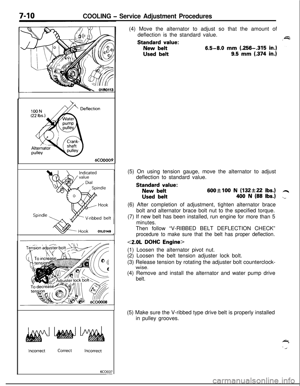
6COO37-(4) Move the alternator to adjust so that the amount of
deflection is the standard value.Standard
value:
New belt6.5-8.0 mm (.256-.315 in.)
Used belt9.5 mm (.374 in.)(5) On using tension gauge, move the alternator to adjust
deflection to standard value.Standard
value:
New belt600flOO N (132+22 Ibs.)
Used belt400 N (88 Ibs.)(6) After completion of adjustment, tighten alternator brace
bolt and alternator brace bolt nut to the specified torque.
(7) If new belt has been installed, run engine for more than 5
minutes.Then follow “V-RIBBED BELT DEFLECTION CHECK”
procedure to make sure that the belt has proper deflection.
<2.0L DOHC Engine>
(1) Loosen the alternator pivot nut.
(2) Loosen the belt tension adjuster lock bolt.
(3) Release tension by rotating the adjuster bolt counterclock-
wise.(4) Remove and install the alternator and water pump drive
belt.(5) Make sure the V-ribbed type drive belt is properly installed
in pulley grooves.
Page 259 of 1216
COOLING - Service Adjustment Procedures7-m
1(6) Adjust belt deflection by tightening adjust bolt.
:Turn adjuster bolt clockwise to increase the belt tension
and turn adjuster bolt counterclockwise to decrease the
belt tension.
Standard value:
New belt7.5-9.0 mm (.295-.354 in.)
Used belt10.0 mm (.394 in.)(7) On using tension gauge, move the alternator to adjust
deflection to standard value.
Standard value:
New belt600+100 N (132f22 Ibs.)
Used belt
400 N (88 Ibs.)(8) Tighten in order, first, adjuster lock bolt then alternator
pivot nut to the specified torque.
(9) If new belt has been installed, run engine for more than 5
minutes. Then follow “DRIVE BELT TENSION INSPEC-
TION” procedure to make sure that the belt has proper
tension and readjust if necessary.