Page 367 of 1216

r-.ENGINE <2.0L DOHC Engine>
- Engine AssemblyS-83
OlA0177
-mpp.-/- --OlA0553
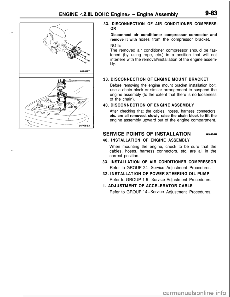
33. DISCONNECTION OF AIR CONDITIONER COMPRESS-
ORDisconnect air conditioner compressor connector and
remove it with hoses from the compressor bracket.
NOTEThe removed air conditioner compressor should be fas-
tened (by using rope, etc.) in a position that will not
interfere with the removal/installation of the engine assem-
bly.
38. DISCONNECTION OF ENGINE MOUNT BRACKET
Before removing the engine mount bracket installation bolt,use a chain block or similar arrangement to suspend the
engine assembly (to the extent that there is no looseness
of the chain).
40. DISCONNECTION OF ENGINE ASSEMBLY
After checking that the cables, hoses, harness connectors,etc. are all removed, slowly raise the chain block to lift the
engine assembly upward out of the engine compartment.
SERVICE POINTS OF INSTALLATION
NOSSDAU
40. INSTALLATION OF ENGINE ASSEMBLYWhen mounting the engine, check to be sure that the
cables, hoses, harness connectors, etc. are all in the
correct position.
33. INSTALLATION OF AIR CONDITIONER COMPRESSORRefer to GROUP
24-Service Adjustment Procedures.
32. INSTALLATION OF POWER STEERING OIL PUMPRefer to GROUP 1
g-service Adjustment Procedures.
1. ADJUSTMENT OF ACCELERATOR CABLERefer to GROUP 14-Service Adjustment Procedures.
Page 368 of 1216

9-84ENGINE <2.0L DOHC Engine> -Camshafts and Camshaft Oil Seals
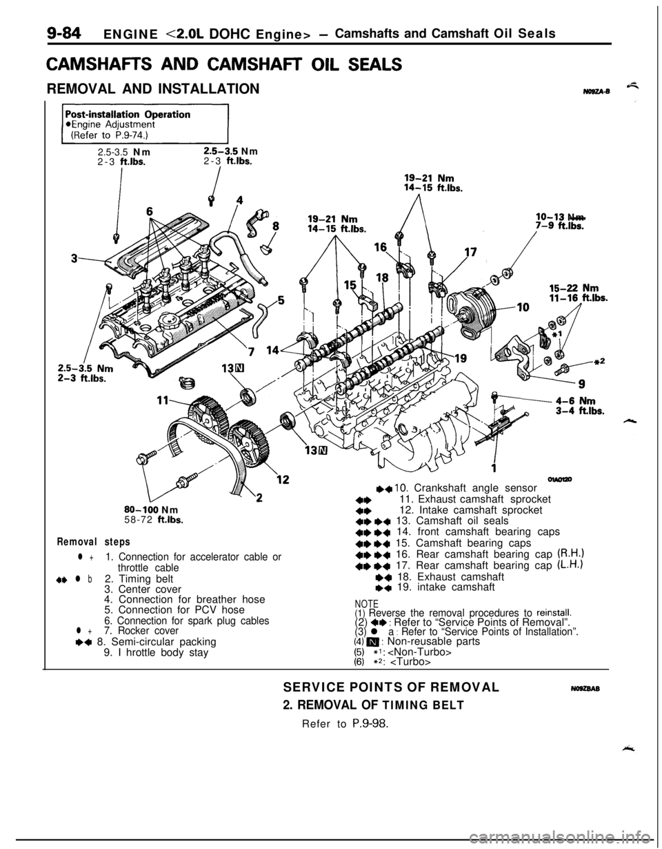
CAMSHAFR AND CAMSHAR OIL SEALSREMOVAL AND INSTALLATION
No8u-s
ppEJ=-j2.5-3.5 Nm
2.5-3.5 Nm
2-3 ft.lbs.2-3 ft.lbs.
lo-13 Nm
olmlzo++ 10. Crankshaft angle sensor
a*11. Exhaust camshaft sprocket80-100 Nm4*12. Intake camshaft sprocket
58-72 ftlbs.+e *+ 13. Camshaft oil seals
Removal steps+e e+ 14. front camshaft bearing caps41)
+4 15. Camshaft bearing caps
l +1. Connection for accelerator cable or+e +c 16. Rear camshaft bearing cap (R.H.)
throttle cable+e +4 17. Rear camshaft bearing cap (L.H.)
d+ l b2. Timing belt~~ 18. Exhaust camshaft
3. Center cover+q 19. intake camshaft
4. Connection for breather hose
5. Connection for PCV hose
NOTE
6. Connection for spark plug cables(1) Reverse the removal procedures to reinstall.(2) 4* : Refer to “Service Points of Removal”.l +7. Rocker cover
(3) l a : Refer to “Service Points of Installation”.~~ 8. Semi-circular packing(4) m : Non-reusable parts
9. I hrottle body stay
1:;*I: ~2:
SERVICE POINTS OF REMOVAL
No9zsAB
2. REMOVAL OF TIMING BELTRefer to P.9-98.
Page 369 of 1216

ENGINE <2.0L DOHC Engine> -Camshafts and Camshaft Oil Seals9-85Plastic hammer
Intake side
Exhaust side
Jzzl
(22
Slits
11. REMOVAL OF EXHAUST CAMSHAFT SPROCKET/
12. INTAKE CAMSHAFT SPROCKET(1) Using a wrench at the hexagonal part of the camshaft
(to prevent the crankshaft from turning), loosen the
cramshaft sprocket bolt.
(2) Remove the camshaft sprokets.
13. REMOVAL OF CAMSHAFT OIL SEALSRemove the oil seals using a screwdriver or similar tool.
Caution
Take care not to damage front camshaft bearing cap
and camshaft.
14./15./16./17. REMOVAL OF CAMSHAFT BEARfNG CAPS(1) Loosen the bearing cap installation bolts in two or
three steps.
(2) Remove the bearing cap.
NOTEIf the bearing cap is difficult to remove, use a plastic
hammer to gently tap the rear
.part of the camshaft,
and then remove.
SERVICE POINTS OF INSTALLATIONNO92DAB
lg. INSTALLATION OF INTAKE CAMSHAFT/18. EXHAUST
CAMSHAFT(1) Install the camshafts on the cylinder head.
Caution
Be sure not to mistake the intake side and the
exhaust side. There are slits for crank angle sensor
drive in the rear end of the intake camshaft.
NOTEInstall new camshafts using the following procedure.
(1) Remove the rocker arms.
(2) Lay the camshafts on the cylinder head and install
the bearing caps.
(3) Check that the camshaft can be easily turned by
hand.(4) After checking, remove the bearing caps and the
camshafts, and install the rocker arms.
Page 371 of 1216

ENGINE <2.0L DOHC Engine> -Camshafts and Camshaft Oil Seals/Oil Pan and Oil Screen9-87
7. INSTALLATION OF ROCKER COVERApply a coating of the specified sealant where shown in
the figure, and then install the rocker cover to the cylinder
head assembly.
Apply sealant
mmin.)
Specified sealant: MOPAR Part No.4318034
or equivalent
olmO47
2. INSTALLATION AND ADJUSTMENT OF TIMING BELTRefer to
P.9-104.
1. ADJUSTMENT OF ACCELERATOR CABLERefer to GROUP 14-Service adjustment procedures.
OIL PAN AND OIL SCREENNO9HA-BREMOVAL AND INSTALLATION
/
/j<&(Refer to GROUP O-Maintenance
\ I/“!18
III13
12-
Removal steps
1.Drain plug2.Self locking nut15-22Nm3.Centermember11-16ft.lbs.7. Connection for exhaust pipe
8.Gasket
9. Connection for oil return pipe (Turbo:IO. Gasket (Turbo)
l * l * 11.Oil pan12.Oil screen
13.Gasket
50-65 Nm*36-47 ft.lbs.*
/117‘1
35-45 NmI25-33 ft.ll3s.
NOTE(I) Reverse the removal procedures to reinstall.(2) l e : Refer to “Service Points of Removal”.
(3) l + : Refer to “Service Points of Installation”.
(4) m : Non-reusable parts
(5)For tightening locations indicated by the * symbol, firsttighten temporarily, and then make the final trghtenrngwith the entire weight of the engine applied to the
vehicle body.
Page 372 of 1216
9-88ENGINE <2.0L DOHC Engine> - Oil Pan and Oil Screen
/
40-60 Nm
30-40 Nm22-29 ft.lbs..
/80-100 Nm458-72
ft.lbs.
70-80 Nm-51-58 ftlbs.15-22 vNm11-16 ft
11b1
Removal steps
1.Drain plug4.Left member
l *5. Transfer assembly6.Drive shaft
7. Exhaust pipe connection
8.Gasket9. Oil return pipe connection
10.Gasket***+ll. Oilpan
12.Oil screen13.Gasket
35-4; Nm25-33 ftlbs.
OlAO620
NOTE(I) Reverse the removal procedures to reinstall.(2) +I) : Refer to “Service Points of Removal”.
(3) H : Refer to “Service Points of Installation”.(4) m : Non-reusable parts
SERVICE POINTS OF REMOVAL
NOBHBAFal
5. REMOVAL OF TRANSFER ASSEMBLYRefer to GROUP 21-Transfer.
11. REMOVAL OF OIL PAN
(1) Remove the oil pan mounting bolts.
(2) Tap the special tool in between the cylinder block and
the oil pan.
Caution
Do not use a screwdriver, a chisel or a similar tool
when removing the oil pan.
(3) Remove the oil pan by placing a brass bar at the correctof the special tool and then tapping with a hammer.
Page 373 of 1216
ENGINE <2.0L DOHC Engine> - Oil Pan and Oil Screen9-89
Sealant
Grooveole of bolt
0180052
INSPECTION&SHOW
lCheck the oil pan for damage and cracks. Replace if faulty.l Check the oil screen for clogging; damage and cracks.
Replace if faulty.
SERVICE POINTS OF INSTALLATION
NOSHDASa
11. INSTALLATION OF OIL PAN
(1) Use a wire brush or other tool to scrape clean all gasketsurfaces of the cylinder block and oil pan so that all
loose material is removed.
(2) Gasket surfaces must be free of oil and dirt.
(3) Apply the specified sealant around the gasket surface
of the oil pan as specified in illustration.
Specified sealant: MITSUBISHI GENUINE PART
No.
MD9971 10 or equivalent
NOTEThe sealant should be applied in a continuous head
approximately 4 mm
(.I 6 in.) in diameter.
(4) Assemble oil pan to cylinder block within 15 minutes
after applying the sealant.
CautionAfter installing the oil pan, wait at least 30 minutes
before starting the engine.
Page 374 of 1216

9-90ENGINE <2.0L DOHC Engine> - Cylinder Head Gasket
CYLINDER HEAD GASKETNOSJA-S2.5-3.5 Nm 19
3 4 K
REIVIOVAL AND INSTALLATION2-3 ft.lbs.\ I i-6
Pre-removal Operation*Eliminating Fuel Pressure in Fuel20Line1\(Refer to GROUP 14-Service Ad-justment Procedures.)eDraining of Engine Coolant(Refer to GROUP 7-Service Adjust-
ment Procedures.)
,,vs4-6 Nm
’
II28
2936’
/w,=
3i38OlAO5.69
Removal stepsl
1. Connection for accelerator cable orthrottle cable
2. Connection for accelerator cable (Auto-
cruise control)3. Connection for oxygen sensor
temperature sensor
5. Connection for engine coolant
temperature gauge unit6. Connection for engine coolant
7. Connection for crank angle sensor
8. Connection for TPS
ISC and idle switch
10. Connection for fuel injector
12. Connection for power transistor
13. Connection for knock sensor (Turbo)
14. Connection for EGR temperature sensor
(California vehicles only)
15. Connection for ground cable
+e l + 17. Connection for radiator upper hose
/\05ADl9019. Center cover
20. Connection for spark plug cable assembly
21. Connection for air intake hose (Turbo)
22. Connection for breather hose (Turbo)
23.Airintakehose24. Connection for breather hose+e l 25. Connection for fuel high pressure hose26. O-ring
27. Connection for vacuum hoses
28. Connection for heater hose
29. Connection for water by-pass hose
30. Connection for PCV hose
31. Connection for vacuum hose (Turbo)
32. Connection for water hose (Turbo)
33. Eye-bolt (Turbo)
34. Gasket (Turbo)
35. Connection for oil pipe (Turbo)
36. Connection for vacuum hoses (Turbo)
37. Connection for fuel return hose
38. Connection for brake booster vacuum
hoseA
NOTE(1) Reverse the removal procedures to reinstall.(2) +I) : Refer to “Service Points of Removal”.
(3) ~~ : Refer to “Service Points of Installation”.
(4) m : Non-reusable parts
Page 375 of 1216
ENGINE <2.0L DOHC Engine> - Cvlinder Head Gasket9-91-_
-2.5-3.5 Nm
2-3
ft.lbs.
I
/
So-100 Nm65-72 ft.lbs.
‘L-\
925-30 Nm
18-22
ft.lbs.55-65 Nm
40-47 ftJbs.27
m43
\
30-40 Nm22-26
ft.lbs.40-60 Nm
29-43
ft.lbs.
Post-installation Operation@Replenishing of Engine Coolant
(Refer to GROUP 7-Service Adjust-
ment Procedures.)
*Engine Adjustment
(Refer to P.9-74.)
48046
45m
4*+439.l +40.+441.42.
43.
44.
22-29 ft.lbs.
45.46.
4* +4 47.+4 48.25-30 Nm
18-22
ft.lbs.
OlA0567
Timing belt
Rocker cover
Semi-circular packing
Self locking nuts
Gasket (Non-Turbo)
Heat protector (Turbo)
Gasket (Turbo)
Ring (Turbo)
Cylinder head assembly
Cylinder head gasket
NOTE(I) Reverse the removal procedures to reinstall.(2) 4e : Refer to “Service Points of Removal”.(3) ++ : Refer to “Service Points of installation”(4) m : Non-reusable parts