Page 411 of 1216
ENGINE <2.0L DOHC Engine> - Piston and Connecting Rod
PISTON AND CONNECTINGRODNonlE-8
cIISASSEMBLY AND REASSEMBLY
6
disassembly steps1. Nut
+e l +2. Connecting rod cap
3. Connecting rod bearing
e+ 4. Piston and connecting rod assembly5. Connecting rod bearing
6. Bolt+e ~~ 7. Piston ring No. 1+e ++ 8. Piston ring No.2
l * 9. Oil ring10. Piston pin11. Piston12. Connecting rod
f86 50-53 Nm36-36 ftlbs.6EN0216
NOTE(1) Reverse the disassembly procedures to reassemble(2) l e : Refer to “Service Points of Disassembly”.(3) +4 : Refer to “Service Points of Reassembly”.
Page 412 of 1216
9-128ENGINE <2.0L DOHC Enaine> - Piston and Connectina Rod
DEN050
6EN185
95EN057
Piston ringring gap6EN037
JSERVICE POINTS OF DISASSEMBLY
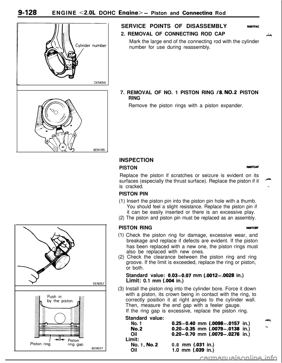
NOSTFAC2. REMOVAL OF CONNECTING ROD CAP
Mark the large end of the connecting rod with the cylinder
number for use during reassembly.
7. REMOVAL OF NO. 1 PISTON RING
/8. NO.2 PISTON
RINGRemove the piston rings with a piston expander.
INSPECTION
PISTONNO@lCAFReplace the piston if scratches or seizure is evident on its
surfaces (especially the thrust surface). Replace the piston if it
is cracked.PISTON PIN
(1) Insert the piston pin into the piston pin hole with a thumb.
You should feel a slight resistance. Replace the piston pin ifit can be easily inserted or there is an excessive play.
(2) The piston and piston pin must be replaced as an assembly.PISTON RING
NOSTCBF
(1) Check the piston ring for damage, excessive wear, and
breakage and replace if defects are evident. If the piston
has been replaced with a new one, the piston rings must
also be replaced with new ones.
(2) Check the clearance between the piston ring and ring
groove. If the limit is exceeded, replace the ring or piston,
or both.
Standard value: 0.03-0.07 mm
(.0012-.0028 in.)
Limit: 0.1 mm
(.004 in.)
(3) Install the piston ring into the cylinder bore. Force it down
with a piston, its crown being in contact with the ring, to
correctly position it at right angles to the cylinder wall.
Then, measure the end gap with a feeler gauge.
If the ring gap is excessive, replace the piston ring.
Standard value:
No. 10.25-0.40 mm (.0098-.0157 in.)
No.20.20-0.35 mm (.0079-.0138 in.)
Oil0.20-0.70 mm (.0079-.0276 in.)
Limit:
No. 1,
No.20.8 mm (.031 in.)
Oil1.0 mm (.039 in.)
Page 413 of 1216
ENGINE <2.0L DOHC Engine> - Piston and Connecting Rodgi’1.29
L
6EN377Side rail gap
I
1 EN062ICONNECTING ROD BEARING
NWTCDD(1) Visually check the bearing surface for uneven contact,
streaks, scratches, and seizure. Replace if defects are
evident. If streaks and seizure are excessive, check also the
crankshaft. If damage is present on the crankshaft, replacecrankshaft or regrind to undersize for reuse.
(2) Measure the connecting rod bearing I.D. and crankshaft pin
O.D. if the oil clearance exceeds the limit, replace bearing,
and crankshaft if necessary. Or, regrind the crankshaft to anundersize and replace bearing with an undersize one.
Standard value:
0.02-0.05 mm (.0008-JO20 in.)
Limit: 0.1 mm
(.004 in.)
NOTEFor oil clearance measuring method using the plastic
gauge, refer to the section CRANKSHAFT.
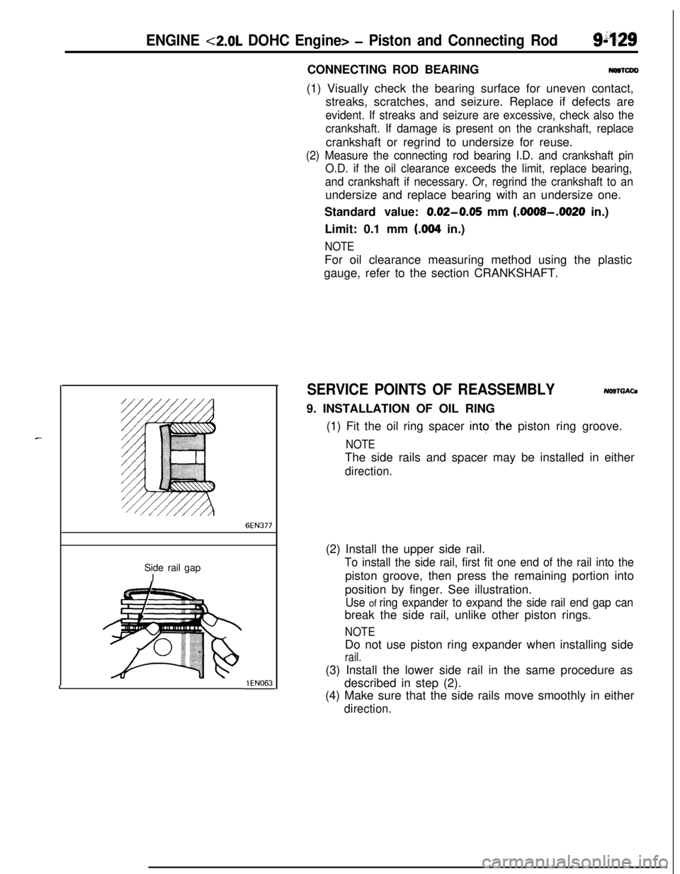
SERVICE POINTS OF REASSEMBLYNO9TGACa9. INSTALLATION OF OIL RING
(1) Fit the oil ring spacer
into’the piston ring groove.
NOTEThe side rails and spacer may be installed in either
direction.(2) Install the upper side rail.
To install the side rail, first fit one end of the rail into thepiston groove, then press the remaining portion into
position by finger. See illustration.
Use of ring expander to expand the side rail end gap canbreak the side rail, unlike other piston rings.
NOTEDo not use piston ring expander when installing side
rail.(3) Install the lower side rail in the same procedure as
described in step (2).
(4) Make sure that the side rails move smoothly in either
direction.
Page 416 of 1216
g-132 ENGINE <2.0L DOHC ‘Engine>- Crankshaft, Flywheel and Drive Plate
CRANKSHAFT, FLYWHEEL AND DRIVE PLATEDISASSEMBLY AND REASSEMBLY
NOBUE-B
1
lo-12 Nm5
7-9 ft.lbs.I
FORWARDIO-12
N/m7-9 ft.lbs.
130-140 Nm94-101 ft.lbs.
I47-51
ftlbs.
130-140 Nm‘94-101 ft.lbs.
6ENO227
Disassembly steps
1. Flywheel (Manual transaxle)
2. Adapter plate3. Drive plateAutomatic
4. Crankshaft bushingtransaxle
5. Rear plate6. Bell housing cover
7. Oil seal case8. Gasket
l + 9. Oil separatorl a 10. Oil seall + 11. Bearing cap
l + 12. Lower bearing
13. Crankshaftl + 14. Upper bearing
NOTE(1) Reverse the disassembly procedures to reassemble.(2) e+ : Refer to “Service Points of Reassembly”.(3) 0 : Non-reusable parts
Page 418 of 1216
g-134 ENGINE <2.0L DOHC Engine>- Crankshaft, Flywheel and Drive Plate
3EN301CRANKSHAFT REAR OIL SEAL
(1) Check oil seal lip for wear and damage.
(2) Check rubber for deterioration or hardening.
(3) Check oil seal case for cracks and damage.
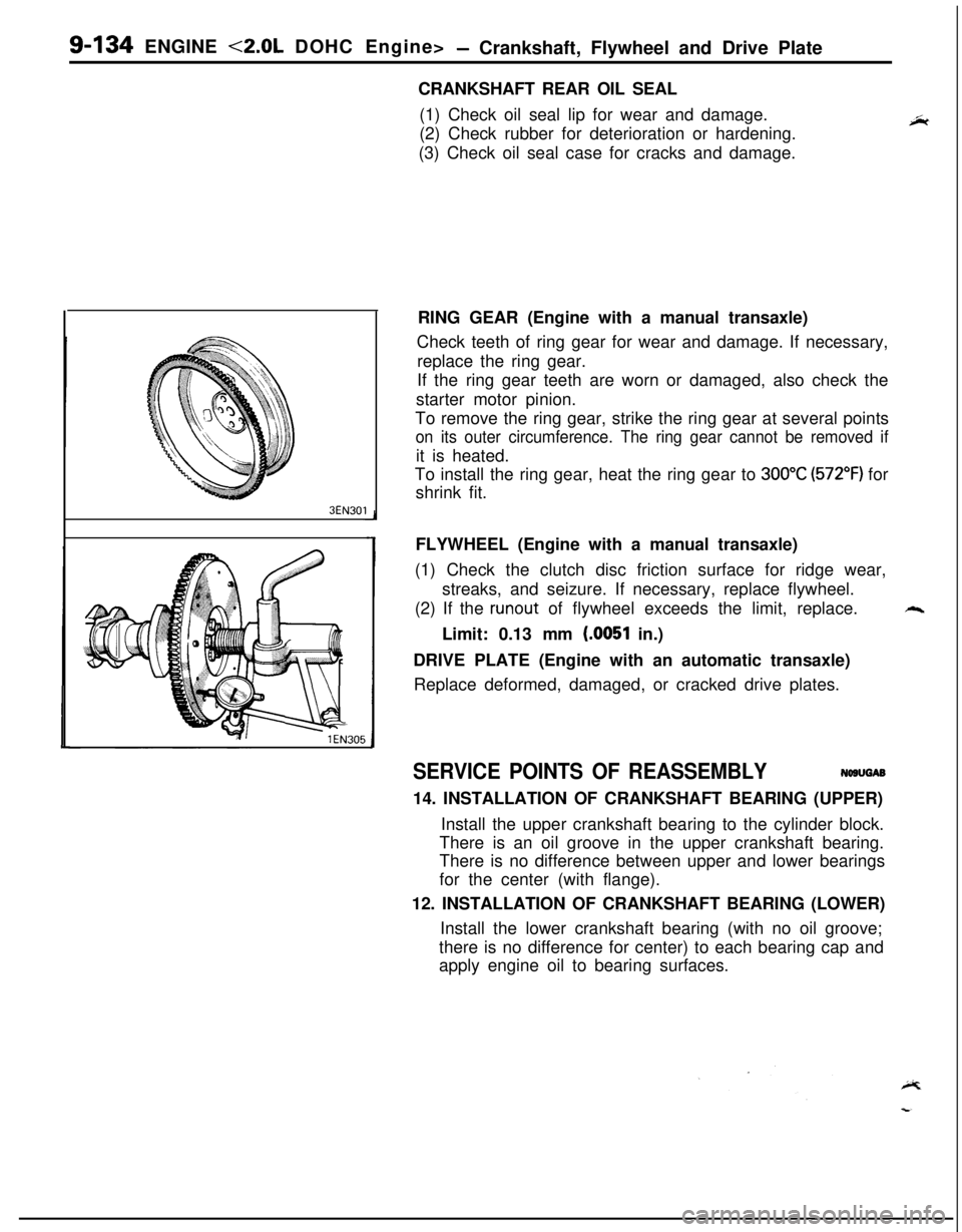
RING GEAR (Engine with a manual transaxle)
Check teeth of ring gear for wear and damage. If necessary,
replace the ring gear.
If the ring gear teeth are worn or damaged, also check the
starter motor pinion.
To remove the ring gear, strike the ring gear at several points
on its outer circumference. The ring gear cannot be removed ifit is heated.
To install the ring gear, heat the ring gear to
300°C (572°F) for
shrink fit.
FLYWHEEL (Engine with a manual transaxle)
(1) Check the clutch disc friction surface for ridge wear,
streaks, and seizure. If necessary, replace flywheel.
(2) If the
runout of flywheel exceeds the limit, replace.++.Limit: 0.13 mm
(.0051 in.)
DRIVE PLATE (Engine with an automatic transaxle)
Replace deformed, damaged, or cracked drive plates.
SERVICE POINTS OF REASSEMBLYNWUGAB
14. INSTALLATION OF CRANKSHAFT BEARING (UPPER)
Install the upper crankshaft bearing to the cylinder block.
There is an oil groove in the upper crankshaft bearing.
There is no difference between upper and lower bearings
for the center (with flange).
12. INSTALLATION OF CRANKSHAFT BEARING (LOWER)
Install the lower crankshaft bearing (with no oil groove;
there is no difference for center) to each bearing cap and
apply engine oil to bearing surfaces.
Page 423 of 1216
11-l
INTAKE AND
EXHAUSTAIR CLEANER
. . . . . . . ..*........................................8
EXHAUST MANIFOLD <1.8L Engine> . . . . . . . .26
EXHAUST MANIFOLD
<2.0L DOHC Engine
(Non-Turbo)>
. . . . . . ..*.*.......................................27EXHAUST MANIFOLD
<2.0L DOHC Engine
(Turbo)>
. . . . . . . . . . . . . . . . . . . . . . . . . . . . . .*...........................28
CONTENTSNllAA--
-EXHAUST PIPE AND MAIN MUFFLER<1.8L Engine,
2.0L DOHC Engine
(Non-Turbo)>
. . . . . . . . . . . . . . . . . . . . .. . . . . . . . . . . . . . . . . . . . . . . . . . . . .30EXHAUST PIPE AND MAIN MUFFLER<2.0L
DOHCEngine(Turbo)>. . . . . . . . . . . . . . . . . . . . .31INTAKE MANIFOLD
<1.8LEngine> . . . . . . . . . . . .13INTAKE MANIFOLD
<2.0L DOHC Engine> 17
INTERCOOLER. . . . . . . . . . . . . . . . . . . . . . . . . . . . . . . . . . . . . . . . . . . . . . . . .11SERVICE ADJUSTMENT PROCEDURES..
.....5Air
Bypass ValveInspection........................7Air Cleaner Element Inspection and
Replacement . .
. . . . . . . . . . . . . . . . . . . . . . . . . . . . . . . . . . . . . . . . . . . . .5Supercharging Pressure Control System
Inspection
.,...... . . . . . . . . . . . . . . . . . . . . . . . . . . . . . . . .. . . . . . . . . . . . . .6Supercharging Pressure Relief Solenoid
Valve Inspection
. . . . . . . . . . . . . . . . . . . . . . . . . . . . . . . . . . . . . . . . . . .7Turbocharger Supercharging Pressure
Inspection. . . . . . . . . . . . . . . . . . . . . . . . . . . . . . . . . . . . . . . . . . . . . . . . . . . . . .6SPECIAL TOOL
. . . . . . . . . . . . . . . . . . . . . . . . . . . . . ..#................4
SPECIFICATIONS.............................................2General Specifications
..................................2Service Specifications
...................................2Torque Specifications
...................................2
TROUBLESHOOTING. . . . . . . . . . . . . . . . . . . . . . . . . . . . . . . . . . . . . .4
Abnormal Noise
Exhaust Gas Leakage
TURBOCHARGER
. . . . . . . . . . . . . . . . . . . . . . . . . . . . . . . . . . . . . . . . . . . .20
Page 424 of 1216
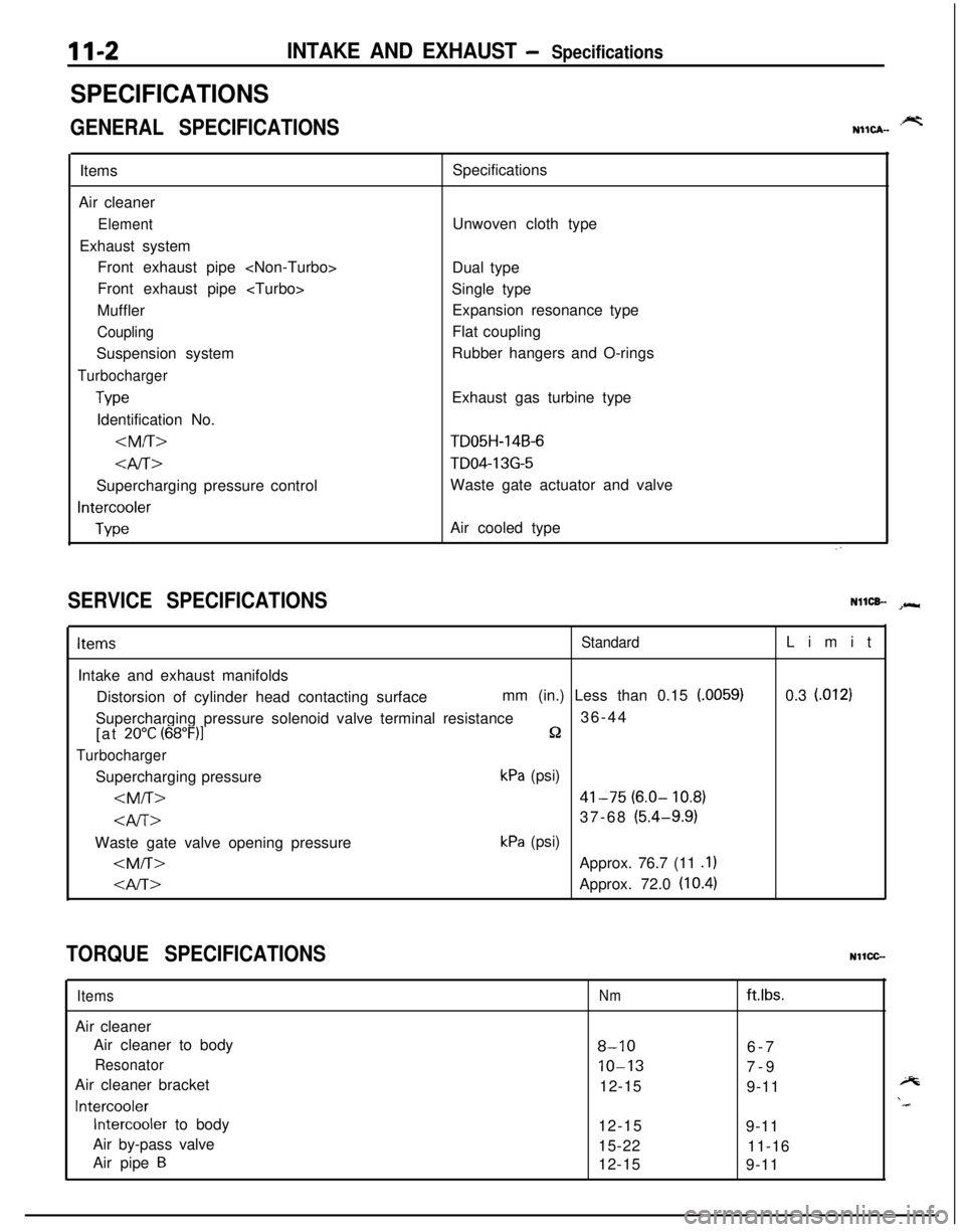
11-2INTAKE AND EXHAUST - Specifications
SPECIFICATIONS
GENERAL SPECIFICATIONS.prtNIICA-Items
Air cleaner
ElementExhaust system
Front exhaust pipe
Front exhaust pipe
Muffler
CouplingSuspension system
Turbocharger
TypeIdentification No.
4iT>Supercharging pressure control
Intercooler
TypeSpecifications
Unwoven cloth type
Dual type
Single type
Expansion resonance type
Flat coupling
Rubber hangers and O-rings
Exhaust gas turbine type
TD05H-14B-6
TD04-13G-5Waste gate actuator and valve
Air cooled type
SERVICE SPECIFICATIONSNllCB- spr*
ItemsStandardIntake and exhaust manifolds
Distorsion of cylinder head contacting surfacemm (in.) Less than 0.15
(.0059)Supercharging pressure solenoid valve terminal resistance36-44
[at
20°C (68”F)lQ
TurbochargerSupercharging pressure
kPa (psi)
41-75 (6.0- 10.8)
37-68 (5.4-9.9)Waste gate valve opening pressure
kPa (psi)
Approx. 76.7 (11 .l)
Approx. 72.0 (10.4)Limit
0.3
l.0121
TORQUE SPECIFICATIONSNllCC-
ItemsAir cleaner
Air cleaner to body
ResonatorAir cleaner bracket
Intercooler
Intercooler to body
Air by-pass valve
Air pipe
B
Nmftlbs.
8-106-7
10-137-9
12-15
9-11
12-15
9-11
15-22
11-16
12-15
9-11
Page 427 of 1216
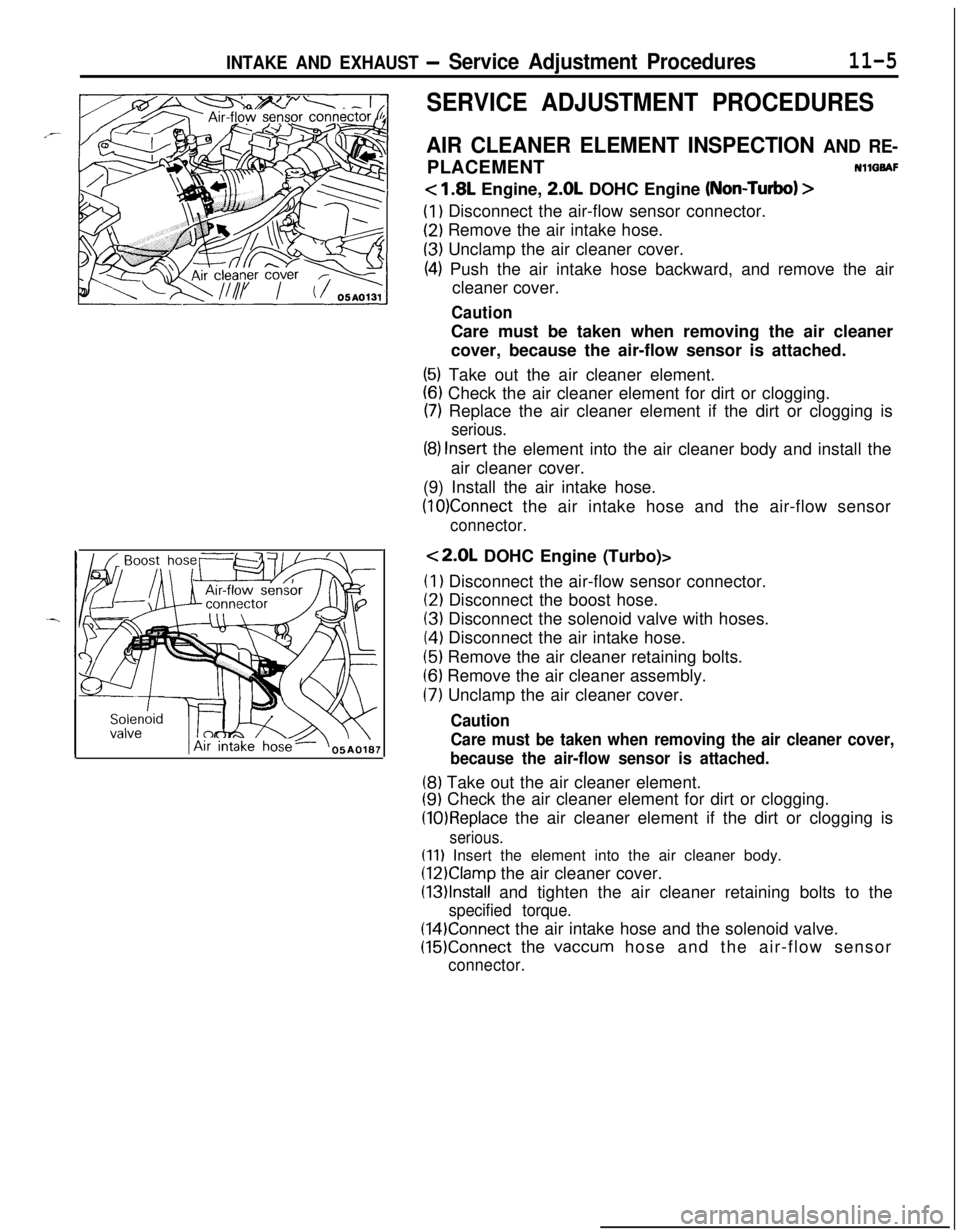
INTAKE AND EXHAUST - Service Adjustment Procedures11-5
SERVICE ADJUSTMENT PROCEDURES
AIR CLEANER ELEMENT INSPECTION AND RE-PLACEMENTNllQBAF
< 1.8L Engine, 2.0L DOHC Engine (Non-Turbo) >
(1) Disconnect the air-flow sensor connector.
(2) Remove the air intake hose.
(3) Unclamp the air cleaner cover.
(4) Push the air intake hose backward, and remove the air
cleaner cover.
CautionCare must be taken when removing the air cleaner
cover, because the air-flow sensor is attached.
(5) Take out the air cleaner element.
(6) Check the air cleaner element for dirt or clogging.
(7) Replace the air cleaner element if the dirt or clogging is
serious.
(8) Insert the element into the air cleaner body and install the
air cleaner cover.
(9) Install the air intake hose.
(10)Connect the air intake hose and the air-flow sensor
connector.
<2.0L DOHC Engine (Turbo)>(I
1 Disconnect the air-flow sensor connector.
(2) Disconnect the boost hose.
(3) Disconnect the solenoid valve with hoses.
(4) Disconnect the air intake hose.
(5) Remove the air cleaner retaining bolts.
(6) Remove the air cleaner assembly.
(7) Unclamp the air cleaner cover.
Caution
Care must be taken when removing the air cleaner cover,
because the air-flow sensor is attached.
(8) Take out the air cleaner element.
(9) Check the air cleaner element for dirt or clogging.
(10)Replace the air cleaner element if the dirt or clogging is
serious.
(11) Insert the element into the air cleaner body.
(12)Clamp the air cleaner cover.
(13)lnstall and tighten the air cleaner retaining bolts to the
specified torque.
(14)Connect the air intake hose and the solenoid valve.
(15)Connect the vaccum hose and the air-flow sensor
connector.