Page 2253 of 4087

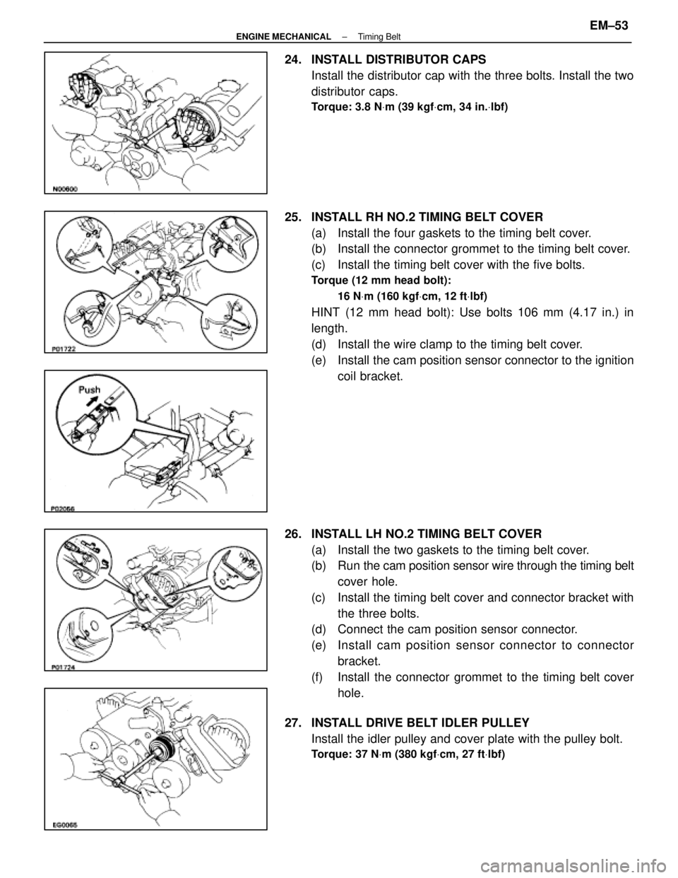
24. INSTALL DISTRIBUTOR CAPSInstall the distributor cap with the three bolts. Install the two
distributor caps.
Torque: 3.8 N Vm (39 kgf Vcm, 34 in. Vlbf)
25. INSTALL RH NO.2 TIMING BELT COVER
(a) Install the four gaskets to the timing belt cover.
(b) Install the connector grommet to the timing belt cover.
(c) Install the timing belt cover with the five bolts.
Torque (12 mm head bolt):
16 NVm (160 kgf Vcm, 12 ft Vlbf)
HINT (12 mm head bolt): Use bolts 106 mm (4.17 in.) in
length.
(d) Install the wire clamp to the timing belt cover.
(e) Install the cam position sensor connector to the ignition
coil bracket.
26. INSTALL LH NO.2 TIMING BELT COVER (a) Install the two gaskets to the timing belt cover.
(b) Run the cam po sition sensor wire through the timing belt
cover hole.
(c) Install the timing belt cover and connector bracket with the three bolts.
(d) Connect the cam position sensor connector.
(e) Install cam position sensor c onnector to connector
bracket.
(f) Install the connector grommet to the timing belt cover hole.
27. INSTALL DRIVE BELT IDLER PULLEY Install the idler pulley and cover plate with the pulley bolt.
Torque: 37 N Vm (380 kgf Vcm, 27 ft Vlbf)
±
ENGINE MECHANICAL Timing BeltEM±53
WhereEverybodyKnowsYourName
Page 2264 of 4087
(b) Remove the two bolts, two nuts, adaptor and gasket.
(c) (USA Spec. only)Disconnect the EGR gas temperature sensor connec-
tor.
14. REMOVE ISC VALVE (a) Disconnect the ISC valve connector.
(b) Disconnect the water by±pass hose from the ISC valve.
(c) Remove the two nuts, ISC valve and gasket.
15. DISCONNECT HEATER WATER VALVE FROM BODY (a) Disconnect the VSV connector.
(b) Remove the bolt holding the engine wire clamp to thewater valve bracket.
(c) Remove the two bolts, and disconnect the water valve and bracket assembly.
16. REMOVE THROTTLE BODY (a) Disconnect the following connectors:(1) Throttle position sensor connector
(2) (w/ TRAC)
Sub±throttle position sensor connector
(3) (w/ TRAC) Sub±throttle actuator connector
EM±64
±
ENGINE MECHANICAL Cylinder Heads
WhereEverybodyKnowsYourName
Page 2268 of 4087

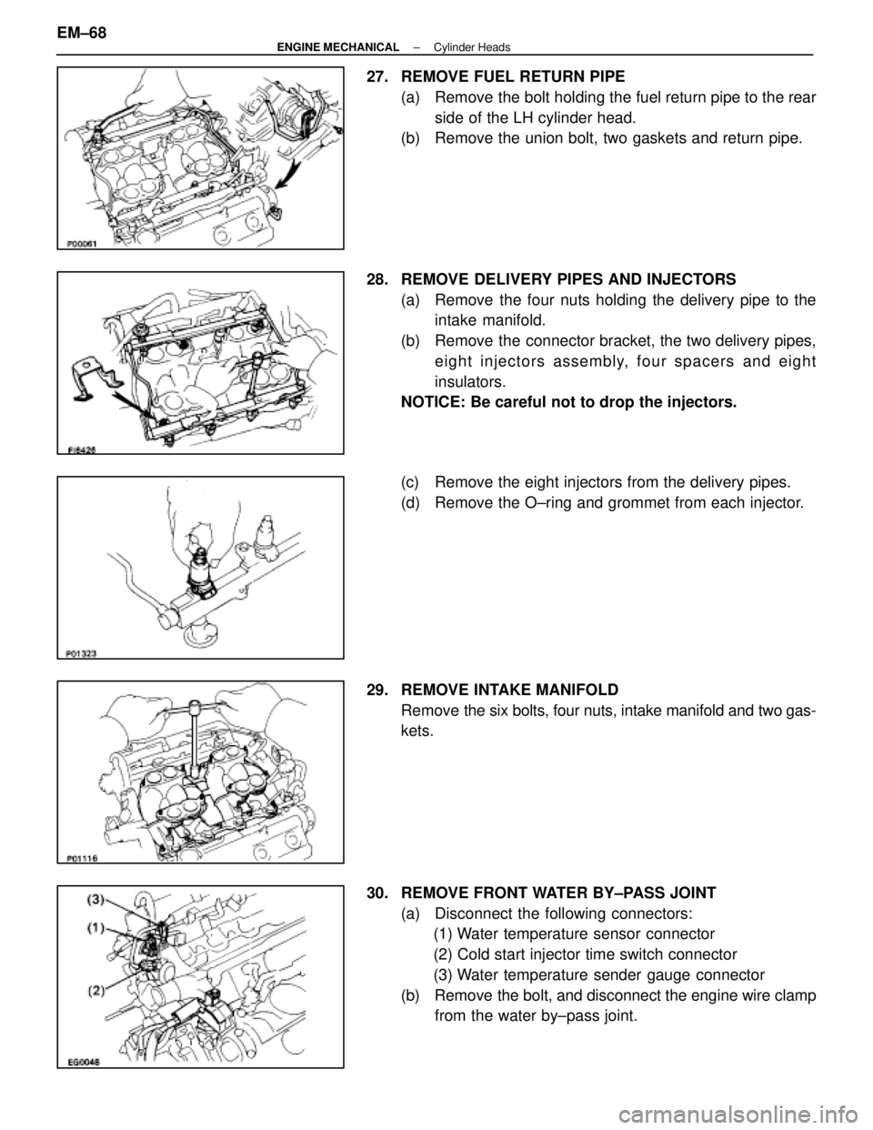
27. REMOVE FUEL RETURN PIPE(a) Remove the bolt holding the fuel return pipe to the rearside of the LH cylinder head.
(b) Remove the union bolt, two gaskets and return pipe.
28. REMOVE DELIVERY PIPES AND INJECTORS (a) Remove the four nuts holding the delivery pipe to theintake manifold.
(b) Remove the connector bracket, the two delivery pipes, eight injectors assembly, four spacers and eight
insulators.
NOTICE: Be careful not to drop the injectors.
(c) Remove the eight injectors from the delivery pipes.
(d) Remove the O±ring and grommet from each injector.
29. REMOVE INTAKE MANIFOLD Remove the six bolts, four nuts, intake manifold and two gas-
kets.
30. REMOVE FRONT WATER BY±PASS JOINT (a) Disconnect the following connectors:(1) Water temperature sensor connector
(2) Cold start injector time switch connector
(3) Water temperature sender gauge connector
(b) Remove the bolt, and disconnect the engine wire clamp from the water by±pass joint.
EM±68
±
ENGINE MECHANICAL Cylinder Heads
WhereEverybodyKnowsYourName
Page 2274 of 4087
(e) Remove the following parts:(1) Wave washer
(2) Camshaft sub±gear
(3) Camshaft gear spring
HINT: Arrange the camshaft sub±gears and gear springs (RH
side and LH side).
43. REMOVE CIRCULAR PLUGS Remove the two bolts, seal washers, bearing cap and circular
plug. Remove the two circular plugs.
HINT: Arrange the bearing caps (RH side and LH side).
44. DISCONNECT MAIN OXYGEN SENSOR CONNECTORS Disconnect the RH and LH oxygen sensor connector.
EM±74
±
ENGINE MECHANICAL Cylinder Heads
WhereEverybodyKnowsYourName
Page 2275 of 4087
45. REMOVE CYLINDER HEADS(a) Uniformly loosen the ten cylinder head bolts on one side
of each cylinder head in several passes in the sequence
shown, then do the other side as shown. Remove the
twenty cylinder head bolts and plate washers.
NOTICE: Head warpage or cracking could result from re-
moving bolts in an incorrect order.
(b) Lift the cylinder heads from the dowels on the cylinder block, and place the two cylinder heads on wooden
blocks on a bench.
HINT: If the cylinder head is difficult to lift off, pry between the
cylinder head and cylinder block with a screwdriver.
NOTICE: Be careful not to damage the contact surfaces
of the cylinder head and cylinder block.
46. REMOVE EXHAUST MANIFOLD FROM RH CYLINDER HEAD
(a) Remove the three bolts and heat insulator.
(b) Remove the main oxygen sensor.
±
ENGINE MECHANICAL Cylinder HeadsEM±75
WhereEverybodyKnowsYourName
Page 2276 of 4087
(c) Remove the eight nuts, exhaust manifold and gasket.
47. REMOVE EXHAUST MANIFOLD FROM LH CYLINDER HEAD
(a) Remove the three bolts and heat insulator.
(b) Remove the main oxygen sensor.
(c) Remove the eight nuts, exhaust manifold and gasket.
DISASSEMBLY OF CYLINDER HEADS
(See Components on page EM±59)
1. REMOVE VALVE LIFTERS AND ADJUSTING SHIMS
EM±76
±
ENGINE MECHANICAL Cylinder Heads
WhereEverybodyKnowsYourName
Page 2291 of 4087
INSTALLATION OF CYLINDER HEADS
(See Components on pages EM±58 and 59)
1. INSTALL RH EXHAUST MANIFOLD TO RH CYLINDER HEAD
(a) Place a new gasket on the cylinder head with the white
painted marks facing the manifold side.
NOTICE: Be careful of the installation direction.
(b) Install the exhaust manifold with the eight new nuts. Uniformly tighten the nuts in several passes.
Torque: 39 N Vm (400 kgf Vcm, 29 ft Vlbf)
(c) Install the main oxygen sensor.
Torque: 44 N Vm (450 kgf Vcm, 33 ft Vlbf)
(d) Install the heat insulator with the three bolts.
2. INSTALL LH EXHAUST MANIFOLD TO LH CYLINDER HEAD
(a) Place a new gasket on the cylinder head with the whitepainted marks facing the manifold side.
NOTICE: Be careful of the installation direction.
±
ENGINE MECHANICAL Cylinder HeadsEM±91
WhereEverybodyKnowsYourName
Page 2292 of 4087
(b) Install the exhaust manifold with the eight new nuts.Uniformly tighten the nuts in several passes.
Torque: 39 N Vm (400 kgf Vcm, 29 ft Vlbf)
(c) Install the main oxygen sensor.
Torque: 44 N Vm (450 kgf Vcm, 33 ft Vlbf)
(d) Install the heat insulator with the three bolts.
3. INSTALL CYLINDER HEADS
A. Place cylinder heads on cylinder block (a) Place two new cylinder head gaskets in position on thecylinder block.
HINT: On the rear side of the cylinder head gasket are
painted marks to distinguish the LH and RH banks, a white
painted mark for the RH bank and a yellow painted mark for
the LH bank.
NOTICE: Be careful of the installation direction.
(b) Place the two cylinder heads in position on the cylinder
head gaskets.
EM±92
±
ENGINE MECHANICAL Cylinder Heads
WhereEverybodyKnowsYourName