Page 2230 of 4087
COMPRESSION CHECK
HINT: If there is lack of power, excessive oil consumption or
poor fuel economy, measure the compression pressure.
1. WARM UP AND STOP ENGINE Allow the engine to warm up to normal operating tempera-
ture.
2. REMOVE NO.3 TIMING BELT COVERS (See steps 1, 5 to 10 and 14 on pages EM±11 to 13)
3. DISCONNECT COLD START INJECTOR CONNECTOR
4. DISCONNECT RH CAM POSITION SENSOR CONNECTOR
(a) Disconnect the connector from the ignition coil bracket.
(b) Disconnect the sensor connector.
5. DISCONNECT LH CAM POSITION SENSOR CONNECTOR
6. REMOVE SPARK PLUGS (a) Disconnect the eight high±tension cords from the sparkplugs.
Disconnect the high±tension cords at rubber boot. Do
not pull on the cords.
NOTICE: Pulling on or bending the cords may damage
the conductor inside.
EM±30
±
ENGINE MECHANICAL Compression Check
WhereEverybodyKnowsYourName
Page 2232 of 4087
9. RECONNECT RH CAM POSITION SENSOR CONNECTOR
(a) Connect the sensor connector.
(b) Connect the connector to the ignition coil bracket.
10. RECONNECT LH CAM POSITION SENSOR CONNECTOR
11. RECONNECT COLD START INJECTOR CONNECTOR
12. REINSTALL NO.3 TIMING BELT COVERS (See steps 28 to 30, 34 to 37, 40 and 41 on pages EM±25
to 27)
EM±32
±
ENGINE MECHANICAL Compression Check
WhereEverybodyKnowsYourName
Page 2238 of 4087
15. REMOVE HIGH±TENSION CORDS, HIGH±TENSIONCORD CLAMPS AND LOWER HIGH±TENSION CORD
COVER ASSEMBLY
(a) Remove the two bolts holding the RH rear high±tensioncord clamp to the cylinder head.
(b) Disconnect the high±tension cords from the RH spark plugs and distributor cap.
(c) Remove the two bolts holding the LH rear high±tension cord clamp to the cylinder head.
(d) Disconnect the high±tension cords from the LH spark
plugs, distributor cap and LH ignition coil.
(e) Remove the bolt holding the lower high±tension cord cover to the water inlet housing.
(f) Disconnect the high±tension cord from the RH ignition
coil, and remove the high±tension cords, clamps and
cover assembly.
16. REMOVE DRIVE BELT IDLER PULLEY Remove the pulley bolt, cover plate and idler pulley.
17. REMOVE RH NO.2 TIMING BELT COVER (a) Disconnect the cam position sensor connector from theignition coil bracket.
EM±38
±
ENGINE MECHANICAL Timing Belt
WhereEverybodyKnowsYourName
Page 2239 of 4087

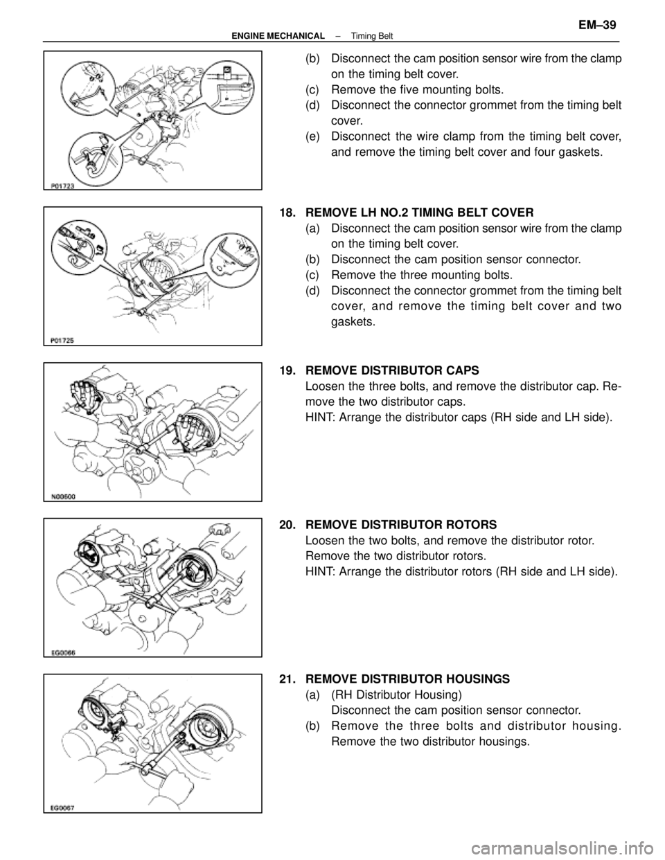
(b) Disconnect the cam position sensor wire from the clamp
on the timing belt cover.
(c) Remove the five mounting bolts.
(d) Disconnect the connector grommet from the timing belt cover.
(e) Disconnect the wire clamp from the timing belt cover, and remove the timing belt cover and four gaskets.
18. REMOVE LH NO.2 TIMING BELT COVER (a) Disconnect the cam position sensor wire from the clamp
on the timing belt cover.
(b) Disconnect the cam position sensor connector.
(c) Remove the three mounting bolts.
(d) Disconnect the connector grommet from the timing belt cover, and remove the timing belt cover and two
gaskets.
19. REMOVE DISTRIBUTOR CAPS Loosen the three bolts, and remove the distributor cap. Re-
move the two distributor caps.
HINT: Arrange the distributor caps (RH side and LH side).
20. REMOVE DISTRIBUTOR ROTORS Loosen the two bolts, and remove the distributor rotor.
Remove the two distributor rotors.
HINT: Arrange the distributor rotors (RH side and LH side).
21. REMOVE DISTRIBUTOR HOUSINGS (a) (RH Distributor Housing)Disconnect the cam position sensor connector.
(b) Re mo ve th e th re e bo lts an d distrib u to r ho u sin g . Remove the two distributor housings.
±
ENGINE MECHANICAL Timing BeltEM±39
WhereEverybodyKnowsYourName
Page 2243 of 4087
(a) Disconnect the solenoid valve connector.
(b) Remove the two mounting bolts and two mounting nuts.
(c) Disconnect the engine speed sensor wire clamp.
(d) Remove the hydraulic pump.
32. REMOVE NO.1 TIMING BELT COVER Remove the four bolts, timing belt cover and gasket.
33. REMOVE TIMING BELT COVER SPACER Remove the cover spacer and gasket.
34. REMOVE TIMING BELT GUIDE (NO.1 CRANK ANGLE SENSOR PLATE)
35. REMOVE TIMING BELT HINT (Re±using timing belt): If the installation marks have
disappeared, place a new installation mark on the timing belt
to match the dot mark of the crankshaft timing pulley.
±
ENGINE MECHANICAL Timing BeltEM±43
WhereEverybodyKnowsYourName
Page 2247 of 4087

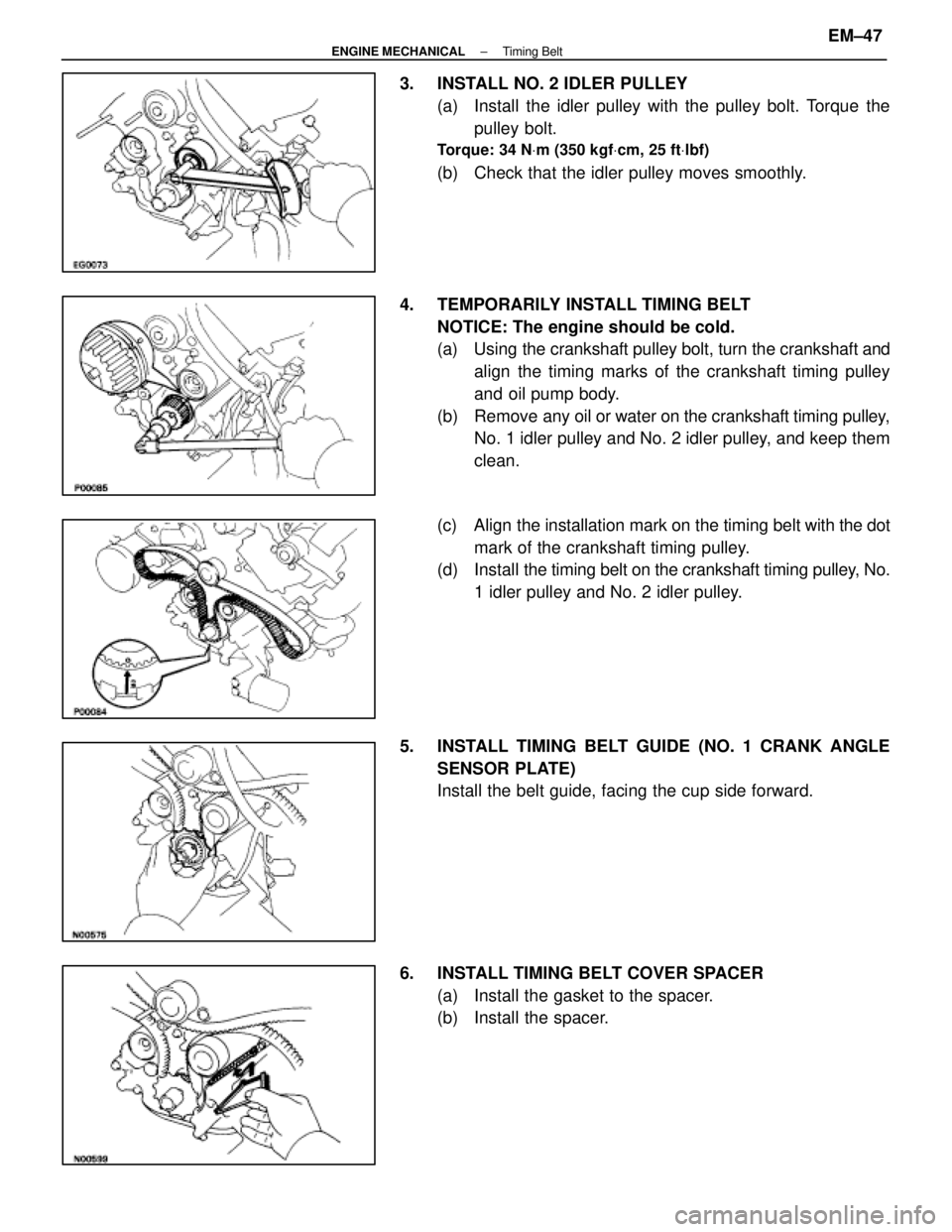
3. INSTALL NO. 2 IDLER PULLEY(a) Install the idler pulley with the pulley bolt. Torque thepulley bolt.
Torque: 34 N Vm (350 kgf Vcm, 25 ft Vlbf)
(b) Check that the idler pulley moves smoothly.
4. TEMPORARILY INSTALL TIMING BELT NOTICE: The engine should be cold.
(a) Using the crankshaft pulley bolt, turn the crankshaft andalign the timing marks of the crankshaft timing pulley
and oil pump body.
(b) Remove any oil or water on the crankshaft timing pulley,
No. 1 idler pulley and No. 2 idler pulley, and keep them
clean.
(c) Align the installation mark on the timing belt with the dot
mark of the crankshaft timing pulley.
(d) Install the timing belt on the crankshaft timing pulley, No.
1 idler pulley and No. 2 idler pulley.
5. INSTALL TIMING BELT GUIDE (NO. 1 CRANK ANGLE SENSOR PLATE)
Install the belt guide, facing the cup side forward.
6. INSTALL TIMING BELT COVER SPACER (a) Install the gasket to the spacer.
(b) Install the spacer.
±
ENGINE MECHANICAL Timing BeltEM±47
WhereEverybodyKnowsYourName
Page 2248 of 4087

7. INSTALL NO.1 TIMING BELT COVER(a) Install the gasket to the timing belt cover.
(b) Install the timing belt cover with the four bolts.
8. INSTALL HYDRAULIC PUMP (a) Install the hydraulic pump and solenoid valve connectorclamp and engine speed sensor wire clamp with the two
bolts and two nuts.
Torque:
12 mm heads 16 N Vm (160 kgf Vcm, 12 ft Vlbf)
Others 30 N Vm (310 kgf Vcm, 22 ft Vlbf)
HINT: Each bolt length is indicated in the illustration.
Bolt length:
A 106 mm (4.17 in.) for 12 mm head
B 114 mm (4.49 in.) for 14 mm head
(b) Connect the solenoid valve connector.
9. INSTALL CRANKSHAFT PULLEY (a) Align the pulley set key on the crankshaft with the keygroove of the pulley.
(b) Using SST and a hammer, tap in the pulley.
SST 09223±46011
(c) Using SST, install and torque the pulley bolt.
SST 09213±70010 and 09330±00021
Torque: 245 N Vm (2,500 kgf Vcm, 181 ft Vlbf)
10. INSTALL RH CAMSHAFT TIMING PULLEY
(a) Align the knock pin on the camshaft with the knock pingroove of the timing pulley.
(b) Slide the timing pulley, facing the ºRº mark forward.
(c) Using SST, install and torque the pulley bolt.
SST 09278±54012
Torque: 108 N Vm (1,100 kgf Vcm, 80 ft Vlbf)
EM±48±
ENGINE MECHANICAL Timing Belt
WhereEverybodyKnowsYourName
Page 2252 of 4087

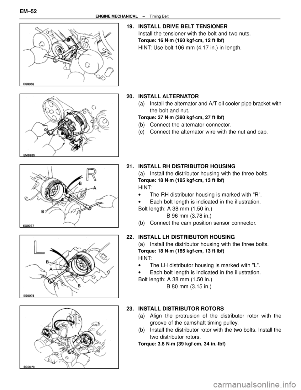
19. INSTALL DRIVE BELT TENSIONERInstall the tensioner with the bolt and two nuts.
Torque: 16 N Vm (160 kgf Vcm, 12 ft Vlbf)
HINT: Use bolt 106 mm (4.17 in.) in length.
20. INSTALL ALTERNATOR (a) Install the alternator and A/T oil cooler pipe bracket withthe bolt and nut.
Torque: 37 N Vm (380 kgf Vcm, 27 ft Vlbf)
(b) Connect the alternator connector.
(c) Connect the alternator wire with the nut and cap.
21. INSTALL RH DISTRIBUTOR HOUSING (a) Install the distributor housing with the three bolts.
Torque: 18 N Vm (185 kgf Vcm, 13 ft Vlbf)
HINT:
w The RH distributor housing is marked with ºRº.
w Each bolt length is indicated in the illustration.
Bolt length: A 38 mm (1.50 in.)
B 96 mm (3.78 in.)
(b) Connect the cam position sensor connector.
22. INSTALL LH DISTRIBUTOR HOUSING (a) Install the distributor housing with the three bolts.
Torque: 18 N Vm (185 kgf Vcm, 13 ft Vlbf)
HINT:
w The LH distributor housing is marked with ºLº.
w Each bolt length is indicated in the illustration.
Bolt length: A 38 mm (1.50 in.)
B 80 mm (3.15 in.)
23. INSTALL DISTRIBUTOR ROTORS (a) Align the protrusion of the distributor rotor with thegroove of the camshaft timing pulley.
(b) Install the distributor rotor with the two bolts. Install the two distributor rotors.
Torque: 3.8 N Vm (39 kgf Vcm, 34 in. Vlbf)
EM±52±
ENGINE MECHANICAL Timing Belt
WhereEverybodyKnowsYourName