Page 2293 of 4087

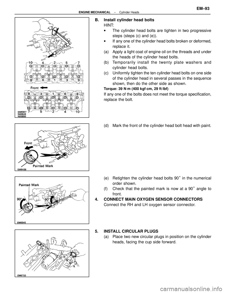
B. Install cylinder head boltsHINT:
wThe cylinder head bolts are tighten in two progressive
steps (steps (c) and (e)).
w If any one of the cylinder head bolts broken or deformed,
replace it.
(a) Apply a light coat of engine oil on the threads and under
the heads of the cylinder head bolts.
(b) Te mp o ra rily in sta ll th e twe n ty pla te wa sh e rs an d cylinder head bolts.
(c) Uniformly tighten the ten cylinder head bolts on one side
of the cylinder head in several passes in the sequence
shown, then do the other side as shown.
Torque: 39 N Vm (400 kgf Vcm, 29 ft Vlbf)
If any one of the bolts does not meet the torque specification,
replace the bolt.
(d) Mark the front of the cylinder head bolt head with paint.
(e) Retighten the cylinder head bolts 90 ° in the numerical
order shown.
(f) Check that the painted mark is now at a 90 ° angle to
front.
4. CONNECT MAIN OXYGEN SENSOR CONNECTORS Connect the RH and LH oxygen sensor connector.
5. INSTALL CIRCULAR PLUGS (a) Place two new circular plugs in position on the cylinderheads, facing the cup side forward.
±
ENGINE MECHANICAL Cylinder HeadsEM±93
WhereEverybodyKnowsYourName
Page 2304 of 4087

19. INSTALL REAR WATER BY±PASS JOINT(a) Install two new gaskets and the water by±pass joint with
the four nuts. Alternately tighten the nuts.
Torque: 18 N Vm (185 kgf Vcm, 13 ft Vlbf)
(b) Install the bolt holding the water by±pass pipe to the
engine hanger.
20. INSTALL FRONT WATER BY±PASS JOINT (a) Install two new gaskets and the water by±pass joint with
the four nuts. Alternately tighten the nuts.
Torque: 18 N Vm (185 kgf Vcm, 13 ft Vlbf)
(b) Install the engine wire clamp with the bolt.
(c) Connect the following connectors:
(1) Water temperature sensor connector
(2) Cold start injector time switch connector
(3) Water temperature sender gauge connector
21. INSTALL INTAKE MANIFOLD (a) Place two new gaskets on the cylinder heads with thewhite painted mark facing upward.
NOTICE: Align the port holes of the gasket and cylinder
head. Be careful of the installation direction.
(b) Place the intake manifold in position on the cylinder head with the arrow mark facing forward.
NOTICE: Be careful of the installation direction.
(c) Install and uniformly tighten the six mounting bolts and
four mounting nuts.
Torque: 18 N Vm (185 kgf Vcm, 13 ft Vlbf)
HINT: Use bolts 30 mm (1.18 in.) in length.
EM±104
±
ENGINE MECHANICAL Cylinder Heads
WhereEverybodyKnowsYourName
Page 2309 of 4087

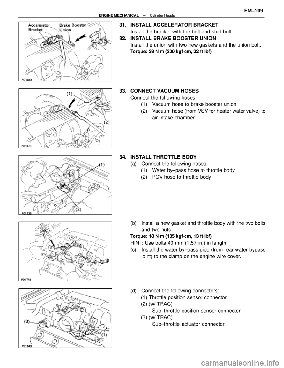
31. INSTALL ACCELERATOR BRACKETInstall the bracket with the bolt and stud bolt.
32. INSTALL BRAKE BOOSTER UNION Install the union with two new gaskets and the union bolt.
Torque: 29 N Vm (300 kgf Vcm, 22 ft Vlbf)
33. CONNECT VACUUM HOSES
Connect the following hoses:(1) Vacuum hose to brake booster union
(2) Vacuum hose (from VSV for heater water valve) to
air intake chamber
34. INSTALL THROTTLE BODY (a) Connect the following hoses:(1) Water by±pass hose to throttle body
(2) PCV hose to throttle body
(b) Install a new gasket and throttle body with the two bolts and two nuts.
Torque: 18 N Vm (185 kgf Vcm, 13 ft Vlbf)
HINT: Use bolts 40 mm (1.57 in.) in length.
(c) Install the water by±pass pipe (from rear water bypass
joint) to the clamp on the engine wire cover.
(d) Connect the following connectors: (1) Throttle position sensor connector
(2) (w/ TRAC) Sub±throttle position sensor connector
(3) (w/ TRAC) Sub±throttle actuator connector
±
ENGINE MECHANICAL Cylinder HeadsEM±109
WhereEverybodyKnowsYourName
Page 2310 of 4087
35. INSTALL HEATER WATER VALVE(a) Install the water valve and bracket assembly with thetwo bolts.
(b) Install the engine wire clamp with the bolt.
(c) Connect the VSV connector.
36. INSTALL ISC VALVE (a) Install a new gasket and the ISC valve with the two nuts.
Torque: 18 N Vm (185 kgf Vcm, 13 ft Vlbf)
(b) Connect the water by±pass hose (from throttle body) to
the ISC valve.
(c) Connect the ISC valve connector.
37. INSTALL EGR VALVE ADAPTOR (a) Install a new gasket, the adaptor and connector bracket(USA spec. only) with the two bolts and two nuts.
Torque: 18 N Vm (185 kgf Vcm, 13 ft Vlbf)
HINT: Use bolts 20 mm (1.79 in.) in length.
NOTICE: Do not touch the air intake chamber and adap-
tor surfaces of the gasket with your hand.
(b) Connect the PCV hose to cylinder head.
(c) (USA Spec. only)
Connect the EGR gas temperature sensor connector.
EM±110
±
ENGINE MECHANICAL Cylinder Heads
WhereEverybodyKnowsYourName
Page 2320 of 4087
12. REMOVE RADIATOR RESERVOIR TANK(a) Disconnect the coolant level sensor connector.
(b) Disconnect the following hoses:(1) Reservoir hose to water inlet housing
(2) Reservoir hose to radiator
(c) Remove the two bolts and reservoir tank bracket.
(d) Disconnect the reservoir tank from the reservoir tank bracket, and remove the reservoir tank.
13. REMOVE RADIATOR (a) Disconnect the water temperature sensor connector.
(b) Disc onnect the wire clamp (for water temperature
sensor) from the radiator fan shrould.
(c) Disconnect the following hoses: (1) Two oil cooler hoses (for cooling fan) from pipes
(2) Two radiator hoses
EM±120
±
ENGINE MECHANICAL Cylinder Block
WhereEverybodyKnowsYourName
Page 2326 of 4087
(i) Remove the bolt holding the engine wire clamp to theheater water valve bracket.
(j) Remove the two bolts holding the engine wire clamp to the body.
(k) Pull out the engine wire from the cabin.
28. REMOVE FRONT EXHAUST PIPE (a) Disconnect the grommet from the floor, and disconnectthe sub±oxygen sensor from the exhaust pipe.
Disconnect the two sub±oxygen sensors.
(b) Remove the four bolts holding the front exhaust pipe to the transmission.
(c) Remove the two bolts and nuts holding the front exhaust
pipe to the center exhaust pipe.
(d) Re mo ve th e fo u r bo lts an d nu ts ho ld in g th e fro n t
exhaust pipe to the catalytic converter. Remove the pipe
support stay, front exhaust pipe and three gaskets.
29. REMOVE CATALYTIC CONVERTERS (MAIN) Remove the three nuts, catalytic converter and gasket. Re-
move the two catalytic converters.
EM±126
±
ENGINE MECHANICAL Cylinder Block
WhereEverybodyKnowsYourName
Page 2330 of 4087
3. DISCONNECT ENGINE WIRE FROM TRANSMISSION(a) Disconnect the following connectors:(1) O/D direct clutch speed sensor connector
(2) No.1 speed sensor connector
(3) No.2 speed sensor connector
(4) Neutral start switch connector
(b) Disconnect the five wire clamps from the brackets on the
transmission.
4. SEPARATE ENGINE AND TRANSMISSION (See AT section)
EM±130
±
ENGINE MECHANICAL Cylinder Block
WhereEverybodyKnowsYourName
Page 2333 of 4087
(b) Disconnect the wire clamp from the bracket on thestarter.
(c) Remove the nut, and disconnect the wire.
(d) Disconnect the connector, and remove the starter.
8. REMOVE KNOCK SENSORS (a) Disconnect the two knock sensor connectors.
(b) Using SST, remove the two knock sensors.
SST 09816±30010
9. REMOVE WATER BY±PASS PIPE (a) Remove the two bolts.
(b) Pull out the by±pass pipe from the water pump.
(c) Remove the O±ring from the by±pass pipe.
10. REMOVE ENGINE WIRE (a) Disconnect the following connectors:(1) Oil level sensor connector
(2) Oil pressure switch connector
(b) Remove the three bolts and wire cover from the LH side
of the cylinder block.
(c) Remove the two bolts and engine wire.
±
ENGINE MECHANICAL Cylinder BlockEM±133
WhereEverybodyKnowsYourName