Page 2454 of 4087
(b) Insert a 0.40 mm (0.016 in.) feeler gauge, between thethrottle stop screw and stop lever.
(c) Connect the test probe of an ohmmeter to the terminals
IDL1 and E2 of the sensor.
(d) Gradually turn the sensor clockwise until the ohmmeter deflects, and secure it with the two set screws.
(e) Recheck the continuity between terminals IDL1 and E2.
Clearance between
lever and stop screwContinuity (IDL1±E2)
0.40 mm (0.016 in.)Continuity
0.65 mm (0.026 in.)No continuity
3. (w/ TRAC) INSPECT SUB±THROTTLE ACTUATOR, SUBTHROTTLE
VALVE AND SUB±THROTTLE POSITION SENSOR
A. Inspect sub±throttle actuator Using an ohmmeter, measure the resistance between the ter-
minals (ACM±A and �, BCM±B and B).
Resistance: 0.5±1.0 �
If the resistance is not as specified, replace the actuator
valve.
B. Inspect sub±throttle actuator Remove the three screws and sub±throttle actuator.
FI±74
EFI SYSTEM
± Air Induction System (Throttle Body)
WhereEverybodyKnowsYourName
Page 2455 of 4087

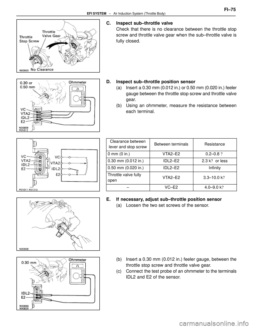
C. Inspect sub±throttle valveCheck that there is no clearance between the throttle stop
screw and throttle valve gear when the sub±throttle valve is
fully closed.
D. Inspect sub±throttle position sensor (a) Insert a 0.30 mm (0.012 in.) or 0.50 mm (0.020 in.) feeler
gauge between the throttle stop screw and throttle valve
gear.
(b) Using an ohmmeter, measure the resistance between each terminal.
Clearance between
lever and stop screwBetween terminalsResistance
0 mm (0 in.)VTA2±E20.2±0.8 �
0.30 mm (0.012 in.)IDL2±E22.3 k� or less
0.50 mm (0.020 in.)IDL2±E2Infinity
Throttle valve fully
openVTA2±E23.3±10.0 k �
±VC±E24.0±9.0 k�
E. If necessary, adjust sub±throttle position sensor
(a) Loosen the two set screws of the sensor.
(b) Insert a 0.30 mm (0.012 in.) feeler gauge, between thethrottle stop screw and throttle valve gear.
(c) Connect the test probe of an ohmmeter to the terminals IDL2 and E2 of the sensor. FI±75
EFI SYSTEM
± Air Induction System (Throttle Body)
WhereEverybodyKnowsYourName
Page 2456 of 4087
(d) Gradually turn the sensor clockwise until the ohmmeterdeflects, and secure it with the two set screws.
(e) Recheck the continuity between terminals IDL2 and E2.
Clearance between
lever and stop screwContinuity (IDL2±E2)
0.30 mm (0.012 in.)Continuity
0.50 mm (0.020 in.)No continuity
E. Reinstall sub±throttle actuator Install the sub±throttle actuator with the three screws.
FI±76
EFI SYSTEM
± Air Induction System (Throttle Body)
WhereEverybodyKnowsYourName
Page 2458 of 4087
(4) Heater water hose to heater water valve
(f) Connect the following connectors: (1) Throttle position sensor connector
(2) (w/ TRAC)
Sub±throttle position sensor connector
(3) (w/ TRAC) Sub±throttle actuator connector
2. INSTALL UPPER HIGH±TENSION CORD COVER (a) Fit portion A of the upper high±tension cover, matchingit with the top of the lower high±tension cord cover.
(b) Push the front side of the high±tension cord cover, and connect the front side claw groove of the upper
high±tension cord cover to the claw of the lower
high±tension cord cover.
(c) Install the upper high±tension cord cover with the two bolts.
3. INSTALL INTAKE AIR CONNECTOR (a) Connect the end portions of the intake air connector tothe throttle body and air cleaner hose.
(b) Tighten the two hose clamps.
(c) Install the bolt holding the intake air connector to the
cylinder head cover.
FI±78
EFI SYSTEM
± Air Induction System (Throttle Body)
WhereEverybodyKnowsYourName
Page 2468 of 4087

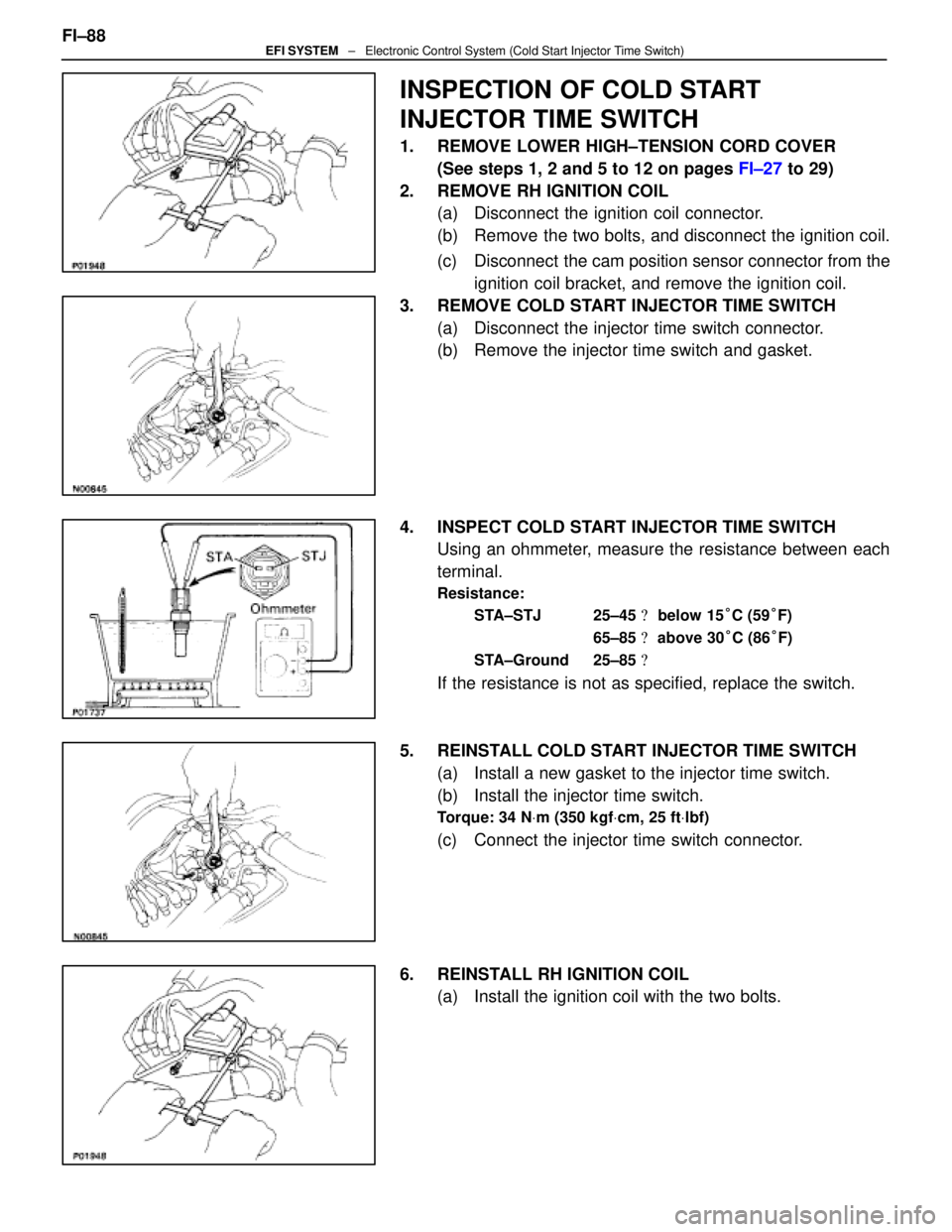
INSPECTION OF COLD START
INJECTOR TIME SWITCH
1. REMOVE LOWER HIGH±TENSION CORD COVER(See steps 1, 2 and 5 to 12 on pages FI±27 to 29)
2. REMOVE RH IGNITION COIL (a) Disconnect the ignition coil connector.
(b) Remove the two bolts, and disconnect the ignition coil.
(c) Disconnect the cam position sensor connector from the
ignition coil bracket, and remove the ignition coil.
3. REMOVE COLD START INJECTOR TIME SWITCH (a) Disconnect the injector time switch connector.
(b) Remove the injector time switch and gasket.
4. INSPECT COLD START INJECTOR TIME SWITCH Using an ohmmeter, measure the resistance between each
terminal.
Resistance:
STA±STJ 25±45 � below 15 °C (59 °F)
65±85 � above 30 °C (86 °F)
STA±Ground 25±85 �
If the resistance is not as specified, replace the switch.
5. REINSTALL COLD START INJECTOR TIME SWITCH (a) Install a new gasket to the injector time switch.
(b) Install the injector time switch.
Torque: 34 N Vm (350 kgf Vcm, 25 ft Vlbf)
(c) Connect the injector time switch connector.
6. REINSTALL RH IGNITION COIL (a) Install the ignition coil with the two bolts.
FI±88
EFI SYSTEM
± Electronic Control System (Cold Start Injector Time Switch)
WhereEverybodyKnowsYourName
Page 2469 of 4087
(b) Install the cam position sensor connector to the ignitioncoil bracket.
(c) Connect the ignition coil connector.
7. REINSTALL LOWER HIGH±TENSION CORD COVER (See steps 1 to 13 and 16 to 18 on pages FI±39 to 41)FI±89
EFI SYSTEM
± Electronic Control System (Cold Start Injector Time Switch)
WhereEverybodyKnowsYourName
Page 2478 of 4087
Water Temperature Sensor
COMPONENTS FOR REMOVAL AND
INSTALLATION
FI±98 ± Electronic Control Sys\
tem (Water Temperature Sensor)EFI SYSTEM
WhereEverybodyKnowsYourName
Page 2479 of 4087

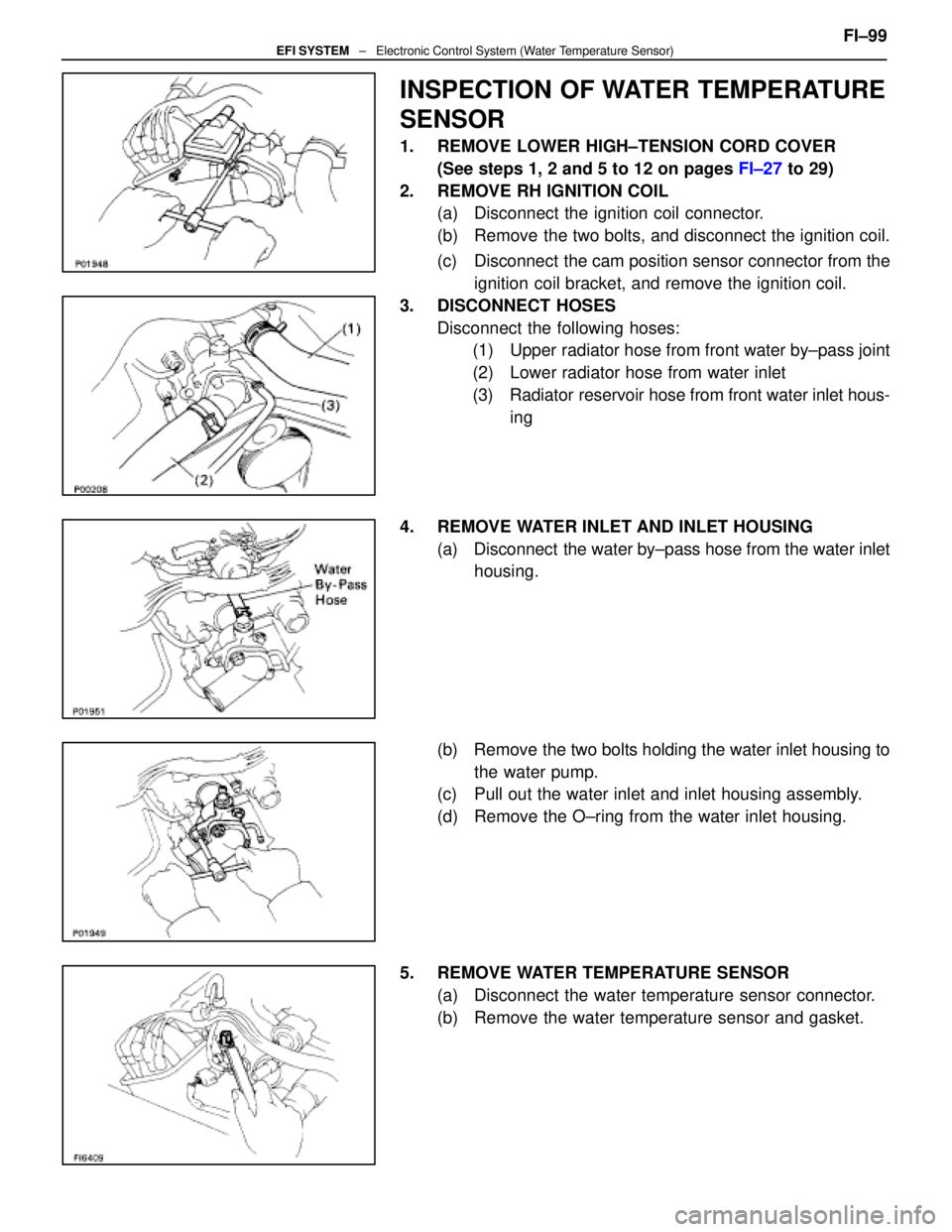
INSPECTION OF WATER TEMPERATURE
SENSOR
1. REMOVE LOWER HIGH±TENSION CORD COVER(See steps 1, 2 and 5 to 12 on pages FI±27 to 29)
2. REMOVE RH IGNITION COIL (a) Disconnect the ignition coil connector.
(b) Remove the two bolts, and disconnect the ignition coil.
(c) Disconnect the cam position sensor connector from the
ignition coil bracket, and remove the ignition coil.
3. DISCONNECT HOSES Disconnect the following hoses:(1) Upper radiator hose from front water by±pass joint
(2) Lower radiator hose from water inlet
(3) Radiator reservoir hose from front water inlet hous-
ing
4. REMOVE WATER INLET AND INLET HOUSING (a) Disconnect the water by±pass hose from the water inlethousing.
(b) Remove the two bolts holding the water inlet housing to the water pump.
(c) Pull out the water inlet and inlet housing assembly.
(d) Remove the O±ring from the water inlet housing.
5. REMOVE WATER TEMPERATURE SENSOR (a) Disconnect the water temperature sensor connector.
(b) Remove the water temperature sensor and gasket. FI±99
EFI SYSTEM
± Electronic Control System (Water Temperature Sensor)
WhereEverybodyKnowsYourName