Page 2514 of 4087

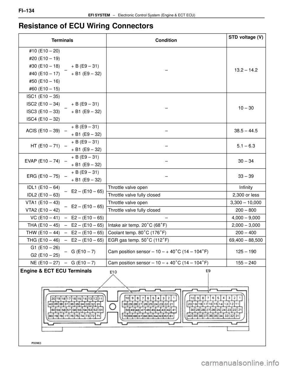
Resistance of ECU Wiring Connectors
TerminalsConditionSTD voltage (V)
#10 (E10 ± 20)
#20 (E10 ± 19)
#30 (E10 ± 18)+ B (E9 ± 31)13 2 14 2#40 (E10 ± 17)±+ B1 (E9 ± 32) ±13.2 ± 14.2
#50 (E10 ± 16)
#60 (E10 ± 15)
ISC1 (E10 ± 35)
ISC2 (E10 ± 34)+ B (E9 ± 31)10 30ISC3 (E10 ± 33)±
+ B1 (E9 ± 32) ±10 ± 30
ISC4 (E10 ± 32)
ACIS (E10 39)+ B (E9 ± 31)38 5 44 5ACIS (E10 ± 39)±
+ B1 (E9 ± 32) ±38.5 ± 44.5
HT (E10 71)+ B (E9 ± 31)51 63HT (E10 ± 71)±
+ B1 (E9 ± 32) ±5.1 ± 6.3
EVAP (E10 74)+ B (E9 ± 31)30 34EVAP (E10 ± 74)±
+ B1 (E9 ± 32) ±30 ± 34
ERG (E10 75)+ B (E9 ± 31)33 39ERG (E10 ± 75)±
+ B1 (E9 ± 32) ±33 ± 39
IDL1 (E10 ± 64)E2 (E10 65)Throttle valve openInfinity
IDL2 (E10 ± 63)± E2 ± (E10 ± 65)Throttle valve fully closed2,300 or less
VTA1 (E10 ± 43)E2 (E10 65)Throttle valve open3,300 ± 10,000
VTA2 (E10 ± 42)± E2 ± (E10 ± 65)Throttle valve fully closed200 ± 800
VC (E10 ± 41)±E2 ± (E10 ± 65)±4,000 ± 9,000
THA (E10 ± 45)±E2 ± (E10 ± 65)Intake air temp. 20
°C (68 °F)2,000 ± 3,000
THW (E10 ± 44)±E2 ± (E10 ± 65)Coolant temp. 80 °C (176 °F)200 ± 400
THG (E10 ± 46)±E2 ± (E10 ± 65)EGR gas temp. 50 °C (112 °F)69,400 ± 88,500
G1 (E10 ± 26)G (E10 7)Camposition sensor 10 + 40°C (14 104°F)125 190G2 (E10 ± 25)±G (E10 ± 7)Cam position sensor ± 10 ± + 40°C (14 ± 104°F)125 ± 190
NE (E10 ± 27)±G (E10 ± 7)Cam position sensor ± 10 ± + 40 °C (14 ± 104 °F)155 ± 240
Engine & ECT ECU Terminals
FI±134EFI SYSTEM ± Electronic Control System (Engine & ECT ECU)
WhereEverybodyKnowsYourName
Page 2517 of 4087

SERVICE SPECIFICATIONS
SERVICE DATA
Fuel pumpResistance0.2 ± 3.0 �
Cold start
injectorResistance
Fuel leakage2 ± 4 �
One drop or less per minute
Fuel pressure
regulatorFuel pressureat no vacuum265 ± 304 kPa
(2.7 ± 3.1 kgf/cm2, 38 ± 44 psi)
InjectorResistance
Injection volume
Difference between each cylinder
Fuel leakage13.4 ± 14.2 �
55 ± 70 cc (3.4 ± 4.3 cu in.) per 15 sec.
10 cc (0.6 cu in.) or less
One drop or less per minute
Air flow meterResistance (THA ± E2)at±20 °C (±4 °F)
at 0 °C (32 °F)
at 20 °C (68 °F)
at 40 °C (104 °F)
at 60 °C (140 °F)
at 80 °C (176 °F)10 ± 20 k �
4 ± 7 k �
2 ± 7 k �
0.9 ± 1.3 k �
0.4 ± 0.7 k �
0.2 ± 0.4 k �
Throttle bodyThrottle body fully closed angle6°
Throttle
positionClearance between
stop screw and leverBetween terminalsResistance
sensor
(main)0 mm
0.40 mm
0.65 mm0 in.
0.016 in.
0.026 in.VTA1 ± E2 IDL1 ± E2
IDL1 ± E2
VTA1 E2
0.2 ± 0.8 k �
2.3 k � or less
Infinity
33 100k �Throttle valve fully opened position
±VTA1 ± E2VC ± E2
y
3.3 ± 10.0 k �
4.0 ± 9.0 k �
Sub±throttle
positionClearance between
stop screw and leverBetween terminalsResistance
sensor
(w/ TRAC)0 mm
0.30 mm
0.50 mm0 in.
0.012 in.
0.020 in.VTA2 ± E2 IDL2 ± E2
IDL2 ± E2
VTA2 E2
0.2 ± 0.8 k �
2.3 k � or less
Infinity
33 100k �Throttle valve fully opened position
±VTA2 ± E2VC ± E2
y
3.3 ± 10.0 k �
4.0 ± 9.0 k �
Sub±throttle
actuator
(w/ TRAC)Resistance (ACM ± A and A, BCM ± B and B)0.5 ± 1.0 �
ISC valveResistance (B1 ± S1 and S3, B2 ± S2 and S4)10 ± 30 �
Cold start
injector time
switchResistance STA ± STJ below 15 °C (59 °F)
above 30 °C (86 °F)
STA ± Ground25 ± 45 �
65 ± 85
25 ± 85 �
VSV for fuel
pressure
controlResistance37 ± 44 �
FI±137 ± Service SpecificationsEFI SYSTEM
WhereEverybodyKnowsYourName
Page 2518 of 4087

SERVICE DATA (Cont'd)
Water temp.
sensorResistanceat ±20°C (±4 °F)
at 0 °C (32 °F)
at 20 °C (68 °F)
at 40 °C (104 °F)
at 60 °C (140 °F)
at 80 °C (176 °F)10 ± 20 k �
4 ± 7 k �
2 ± 7 k �
0.9 ± 1.3 k �
0.4 ± 0.7 k �
0.2 ± 0.4 k �
EGR gas
temp.
sensorResistanceat 50°C (112 °F)
at 100 °C (212 °F)
at 150 °C (302 °F)69 ± 89 k �
12 ± 15 k �
2 ± 4 k �
Main oxygen
sensorHeater coil resistance5.1 ± 6.3 �
Sub±oxygen
sensorHeater coil resistance5.1 ± 6.3 �
ECUHINT:
�Perform all voltage and resistance measurements with the ECU connected.
� Verify that the battery voltage in 11 V or above with the ignition switch is ON.
Voltage
TerminalsConditionSTD voltage (V)
BATT ± E1±10 ± 14
IGSW
+B ± E1
+B1
IG SW ON10 ± 14
VC ± E2±4.0 ± 6.0
IDL1E2
Throttle (or sub±throttle) valve fully closed1 or lessIDL1
IDL2 ± E2
IG SW ONThrottle (or sub±throttle) valve fully open10 ± 14
VTA1E2
Throttle (or sub±throttle) valve fully closed0.1 or lessVTA1
VTA 2 ± E2
Throttle (or sub±throttle) valve fully open3.0 ± 6.0
KS ± E1IdlingPulse generation
THA ± E2
THW±E2Idling
Intake air temp. 20
°C (68 °F)1.0 ± 3.0
THW ± E2IdlingEngine coolant temp. 80 °C (176 °F)0.1 ± 1.0
STA ± E1Cranking6.0 or more
#10
#20
E01IG SW ON10 ± 14#20
#30
#40±
E01
E02IdlingPulse generation
IGT1
IGT2
± E1IdlingPulse generation
FI±138EFI SYSTEM
± Service Specifications
WhereEverybodyKnowsYourName
Page 2521 of 4087
SERVICE DATA (Cont'd)
ECU (cont'd)Resistance of wiring connector side (cont'd)
TerminalsConditionSTD voltage (�)
±
HTR1
HTR2
HTL1
HTL2 +B
+B1±5.1 ± 6.3
±
PA G +B
+B1±30 ± 34
±IDL1 +BThrottle valve fully openInfinity
±IDL1
IDL2
+B
+B1Throttle valve fully closed2,300 or less
±VTA1E2
Throttle valve fully open3,300 ± 10,000
±VTA1
VTA2E2
Throttle valve fully closed200 ± 800
VC ± E2±4,000 ± 9,000
THS ± E2Intake air temp, 20
°C (68 °F)2,000 ± 3,000
THW ± E2Coolant temp. 80 °C (176 °F)200 ± 400
THG ± E2EGR gas temp. 50 °C (112 °F)69,400 ± 88,500
G1
G2 G1 (±)
G2 (±)
±Cam position sensor ± 10 ± +40
°C (14 ± 104 °F)835 ± 1,350
NE ± NE (±)engine speed sensor ± 10 ± +40 °C (14 ± 104 °F)835 ± 1,350
Fuel cut rpmw/ Vehicle speed 0 km/h and coolant temp. 80 °C (176 °F)
Fuel cut rpm
Fuel return rpm
1,800 rpm
1,400 rpm
FI±141EFI SYSTEM ± Service Specifications
WhereEverybodyKnowsYourName
Page 2522 of 4087

TORQUE SPECIFICATIONS
Part tightenedNVmkgf Vcmft Vlbf
Fuel line Union bolt type
Flare nut type2930022
Fuel pipe X Delivery pipe39400 29
Fuel pump bracket X Fuel tank5.455 48 in.Vlbf
Fuel pump set plate X Fuel tank3.940 35 in. Vlbf
Fuel tank X Body25250 18
Fuel sender gauge X Fuel tank2.930 26 in. Vlbf
Fuel inlet pipe X Fuel tank2.930 26 in. Vlbf
Fuel tank main tube X Fuel tank29300 22
Fuel tank return tube X Fuel tank29300 22
Fuel tank evaporation vent tube X Fuel tank29300 22
Air flow meter X Air cleaner case10100 7
Cold start injector X Air intake chamber7.880 69 in. Vlbf
Cold start injector tube X Cold start injector15150 11
Air intake chamber X Intake manifold18185 13
EGR pipe X Air intake chamber18185 13
EGR pipe X RH cylinder head18185 13
Cold start injector tube X RH Delivery pipe15150 11
Throttle body X Air intake chamber18185 13
Fuel return pipe X Fuel pressure regulator35360 26
Fuel pressure regulator X RH delivery pipe29300 22
Delivery pipe X Intake manifold18185 13
Fuel inlet hose X LH delivery pipe39400 29
for SST33340 24
ISC valve X Air intake chamber18185 13
Cold start injector time switch X Front water by±pass joint34350 25
Water temperature sensor X Front water by±pass joint20200 14
Water inlet housing X Water pump18185 13
EGR gas temperature sensor X EGR valve adaptor20200 14
EGR valve adaptor X Air intake chamber18185 13
EGR valve X EGR valve adaptor18185 13
Knock sensor X Cylinder block44450 33
Intake manifold X Cylinder head18185 13
Main oxygen sensor X Exhaust manifold44450 33
Sub±oxygen sensor X Exhaust manifold4445033
FI±142EFI SYSTEM ± Service Specifications
WhereEverybodyKnowsYourName
Page 2524 of 4087

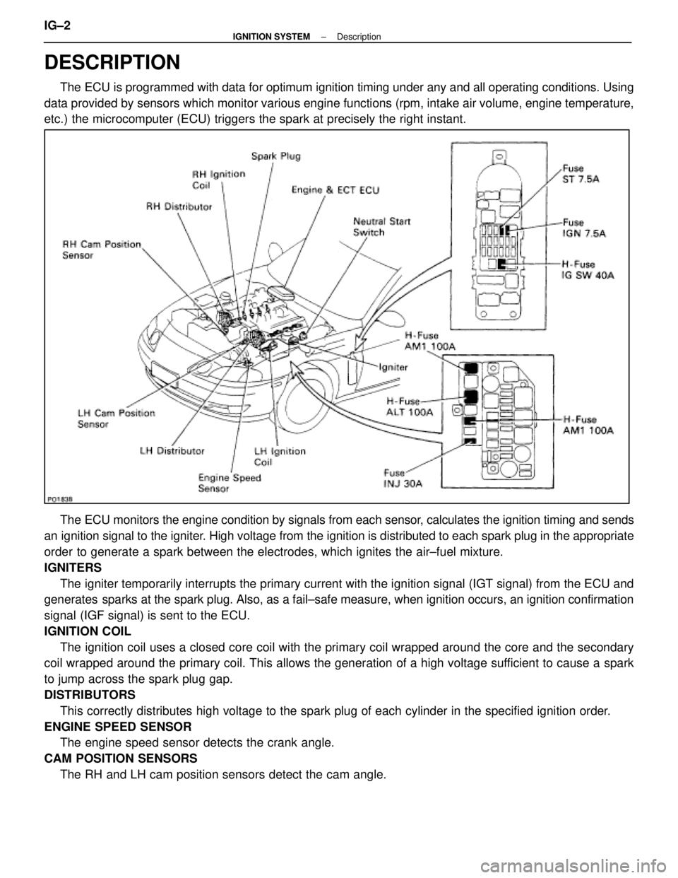
DESCRIPTION
The ECU is programmed with data for optimum ignition timing under any and a\
ll operating conditions. Using
data provided by sensors which monitor various engine functions (rpm, i\
ntake air volume, engine temperature,
etc.) the microcomputer (ECU) triggers the spark at precisely the right ins\
tant.
The ECU monitors the engine condition by signals from each sensor, calculates the ignition timing and sends
an ignition signal to the igniter. High voltage from the ignition is distributed to each spark plug in th\
e appropriate
order to generate a spark between the electrodes, which ignites the air±fu\
el mixture.
IGNITERS The igniter temporarily interrupts the primary current with the ignition si\
gnal (IGT signal) from the ECU and
generates sparks at the spark plug. Also, as a fail±safe measure, when ignitio\
n occurs, an ignition confirmation
signal (IGF signal) is sent to the ECU.
IGNITION COIL
The ignition coil uses a closed core coil with the primary coil wrapped \
around the core and the secondary
coil wrapped around the primary coil. This allows the generation of a hi\
gh voltage sufficient to cause a spark
to jump across the spark plug gap.
DISTRIBUTORS
This correctly distributes high voltage to the spark plug of each cylind\
er in the specified ignition order.
ENGINE SPEED SENSOR The engine speed sensor detects the crank angle.
CAM POSITION SENSORS The RH and LH cam position sensors detect the cam angle.
IG±2
±
IGNITION SYSTEM Description
WhereEverybodyKnowsYourName
Page 2532 of 4087

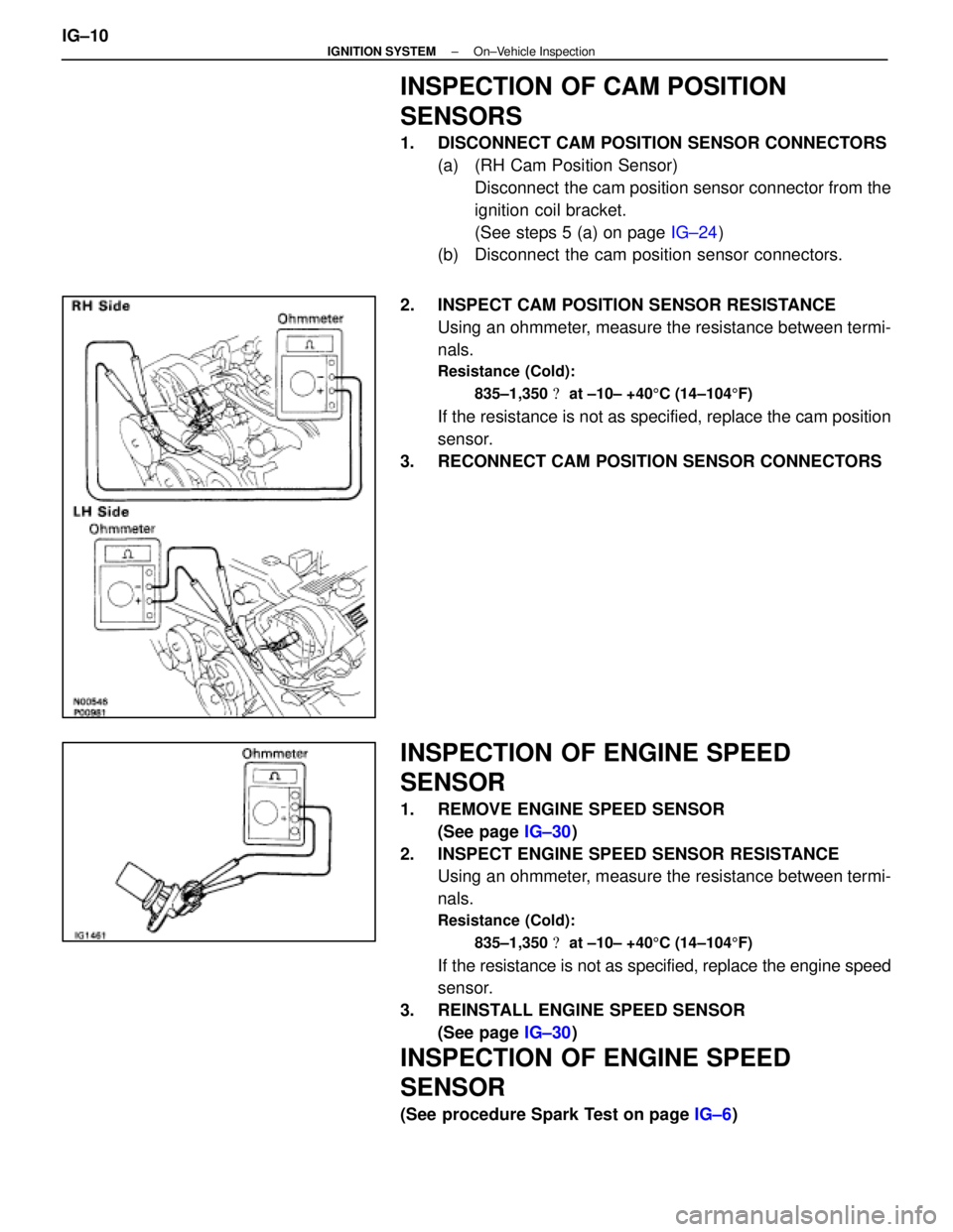
INSPECTION OF CAM POSITION
SENSORS
1. DISCONNECT CAM POSITION SENSOR CONNECTORS(a) (RH Cam Position Sensor)Disconnect the cam position sensor connector from the
ignition coil bracket.
(See steps 5 (a) on page IG±24)
(b) Disconnect the cam position sensor connectors.
2. INSPECT CAM POSITION SENSOR RESISTANCE Using an ohmmeter, measure the resistance between termi-
nals.
Resistance (Cold):
835±1,350 � at ±10± +40 5C (14±104 5F)
If the resistance is not as specified, replace the cam position
sensor.
3. RECONNECT CAM POSITION SENSOR CONNECTORS
INSPECTION OF ENGINE SPEED
SENSOR
1. REMOVE ENGINE SPEED SENSOR (See page IG±30)
2. INSPECT ENGINE SPEED SENSOR RESISTANCE Using an ohmmeter, measure the resistance between termi-
nals.
Resistance (Cold):
835±1,350 � at ±10± +40 5C (14±104 5F)
If the resistance is not as specified, replace the engine speed
sensor.
3. REINSTALL ENGINE SPEED SENSOR (See page IG±30)
INSPECTION OF ENGINE SPEED
SENSOR
(See procedure Spark Test on page IG±6)
IG±10
±
IGNITION SYSTEM On±Vehicle Inspection
WhereEverybodyKnowsYourName
Page 2543 of 4087

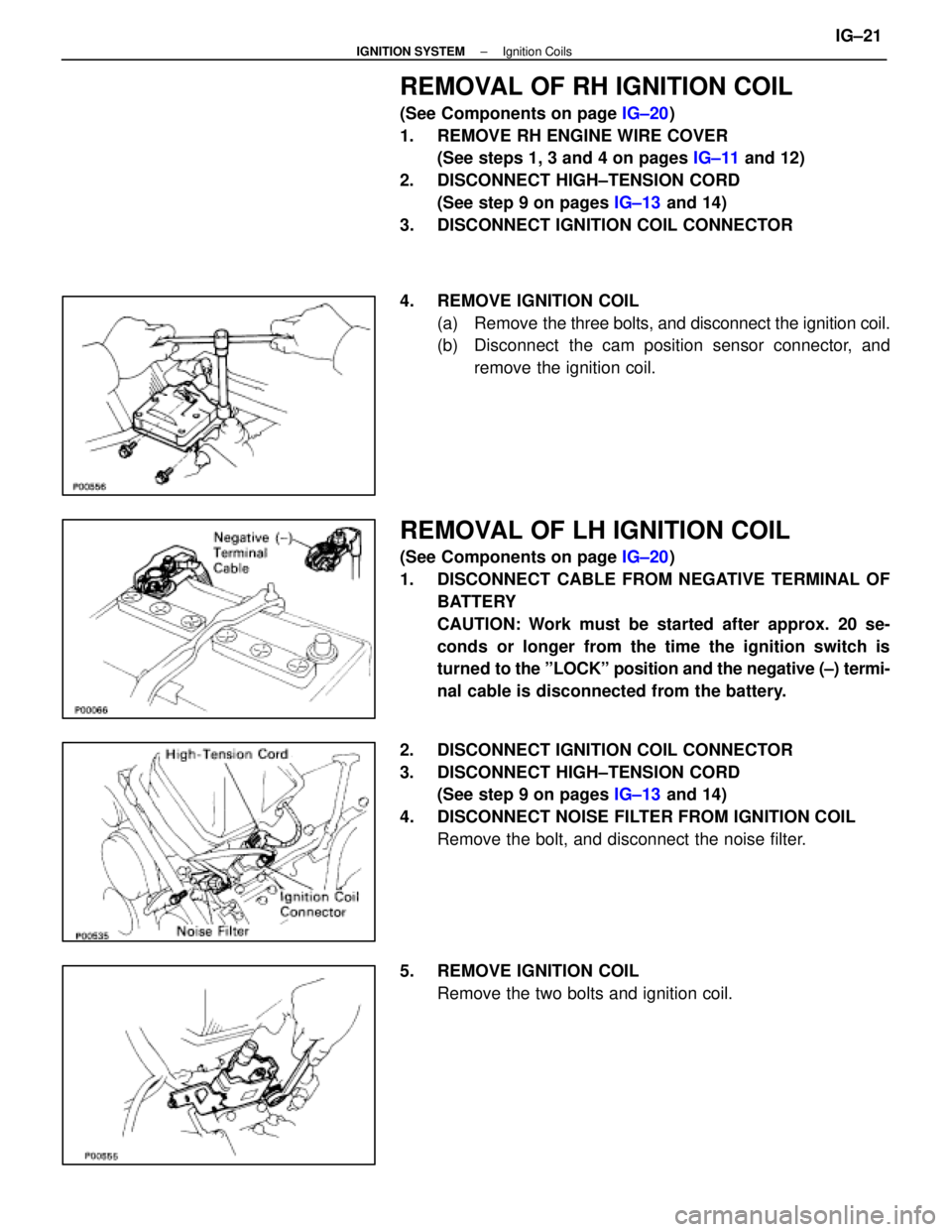
REMOVAL OF RH IGNITION COIL
(See Components on page IG±20)
1. REMOVE RH ENGINE WIRE COVER (See steps 1, 3 and 4 on pages IG±11 and 12)
2. DISCONNECT HIGH±TENSION CORD (See step 9 on pages IG±13 and 14)
3. DISCONNECT IGNITION COIL CONNECTOR
4. REMOVE IGNITION COIL (a) Remove the three bolts, and disconnect the ignition coil.
(b) Disconnect the cam position sensor connector, and
remove the ignition coil.
REMOVAL OF LH IGNITION COIL
(See Components on page IG±20)
1. DISCONNECT CABLE FROM NEGATIVE TERMINAL OF BATTERY
CAUTION: Work must be started after approx. 20 se-
conds or longer from the time the ignition switch is
turned to the ºLOCKº position and the negative (±) termi-
nal cable is disconnected from the battery.
2. DISCONNECT IGNITION COIL CONNECTOR
3. DISCONNECT HIGH±TENSION CORD (See step 9 on pages IG±13 and 14)
4. DISCONNECT NOISE FILTER FROM IGNITION COIL Remove the bolt, and disconnect the noise filter.
5. REMOVE IGNITION COIL Remove the two bolts and ignition coil.
±
IGNITION SYSTEM Ignition CoilsIG±21
WhereEverybodyKnowsYourName