Page 2564 of 4087

REMOVAL OF OIL PUMP
(See Components on page LU±8)
HINT: When repairing the oil pump, the oil pan and strainer
should be removed and cleaned.
1. REMOVE ENGINE WITH TRANSMISSION (See pages EM±118 to 128)
2. SEPARATE ENGINE AND TRANSMISSION (See pages EM±129 to 130)
3. INSTALL ENGINE TO ENGINE STAND FOR REMOVAL
4. REMOVE TIMING BELT (See steps 8 to 35 on pages EM±36 to 43)
5. REMOVE NO.2 IDLER PULLEY, NO.1 IDLER PULLEY AND CRANKSHAFT TIMING PULLEY
(See steps 36 to 38 on page EM±44)
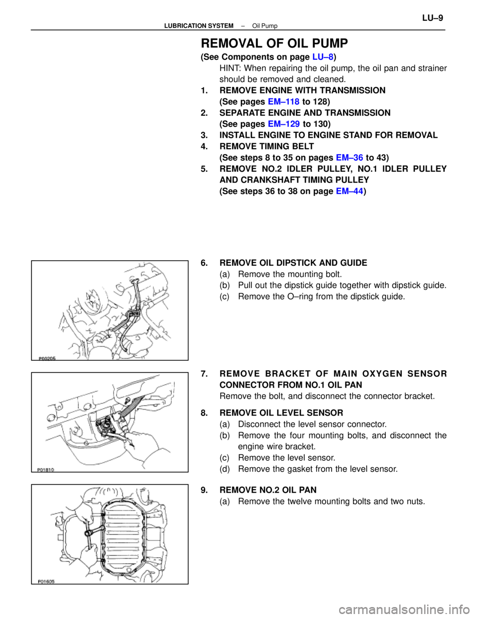
6. REMOVE OIL DIPSTICK AND GUIDE (a) Remove the mounting bolt.
(b) Pull out the dipstick guide together with dipstick guide.
(c) Remove the O±ring from the dipstick guide.
7. REMOVE BRACKET OF MAIN OXYGEN SENSOR CONNECTOR FROM NO.1 OIL PAN
Remove the bolt, and disconnect the connector bracket.
8. REMOVE OIL LEVEL SENSOR (a) Disconnect the level sensor connector.
(b) Remove the four mounting bolts, and disconnect theengine wire bracket.
(c) Remove the level sensor.
(d) Remove the gasket from the level sensor.
9. REMOVE NO.2 OIL PAN (a) Remove the twelve mounting bolts and two nuts.
±
LUBRICATION SYSTEM Oil PumpLU±9
WhereEverybodyKnowsYourName
Page 2566 of 4087
12. REMOVE OIL STRAINERRemove the two bolts, two nuts, oil strainer and gasket.
13. REMOVE OIL FILTER BRACKET (a) Disconnect the oil pressure switch connector.
(b) Remove the two bo lts, stud bolt, the filter bracket and oil
filter assembly.
(c) Remove the gasket from the filter bracket.
14. REMOVE ENGINE SPEED SENSOR (a) Disconnect the speed sensor connector.
(b) Remove the bolt and speed sensor.
15. REMOVE OIL PUMP (a) Remove the eight mounting bolts.
(b) Remove the oil pump by prying the portions between the
cylinder block and oil pump with a screwdriver.
NOTICE: Be careful not to damage the contact surfaces
of the cylinder block and oil pump.
(c) Remove the O±ring from the cylinder block.
±
LUBRICATION SYSTEM Oil PumpLU±11
WhereEverybodyKnowsYourName
Page 2571 of 4087
(e) Install the oil pump with the eight bolts.
Torque:12 mm head 16 N Vm (160 kgf Vcm, 12 ft Vlbf)
14 mm head 30 N Vm (310 kgf Vcm, 22 ft Vlbf)
HINT: Each bolt length is indicated in the illustration.
Bolt length:
A 50 mm (1.97 in.) for 12 mm head
B 106 mm (4.17 in.) for 12 mm head
C 30 mm (1.18 in.) for 12 mm head
D 40 mm (1.57 in.) for 14 mm head
2. INSTALL ENGINE SPEED SENSOR (a) Install the speed sensor with the bolt.
Torque: 6.4 N Vm (65 kgf Vcm, 56 in. Vlbf)
(b) Connect the speed sensor connector.
3. INSTALL OIL FILTER BRACKET (a) Place a new gasket in position on the oil filter bracket.
(b) Install the oil filter bracket with the two bolts and studbolt.
Torque: 18 N Vm (185 kgf Vcm, 13 ft Vlbf)
(c) Connect the oil pressure switch connector.
4. INSTALL OIL STRAINER Install a new gasket and the oil strainer with the two bolts and
two nuts.
Torque: 7.8 N Vm (80 kgf Vcm, 69 in. Vlbf)
LU±16±
LUBRICATION SYSTEM Oil Pump
WhereEverybodyKnowsYourName
Page 2574 of 4087

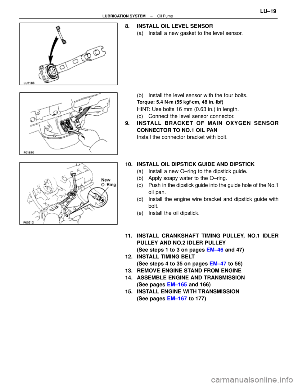
8. INSTALL OIL LEVEL SENSOR(a) Install a new gasket to the level sensor.
(b) Install the level sensor with the four bolts.
Torque: 5.4 N Vm (55 kgf Vcm, 48 in. Vlbf)
HINT: Use bolts 16 mm (0.63 in.) in length.
(c) Connect the level sensor connector.
9. INSTALL BRACKET OF MAIN OXYGEN SENSOR CONNECTOR TO NO.1 OIL PAN
Install the connector bracket with bolt.
10. INSTALL OIL DIPSTICK GUIDE AND DIPSTICK (a) Install a new O±ring to the dipstick guide.
(b) Apply soapy water to the O±ring.
(c) Push in the dipstick guide into the guide hole of the No.1
oil pan.
(d) Install the engine wire bracket and dipstick guide with bolt.
(e) Install the oil dipstick.
11. INSTALL CRANKSHAFT TIMING PULLEY, NO.1 IDLER PULLEY AND NO.2 IDLER PULLEY
(See steps 1 to 3 on pages EM±46 and 47)
12. INSTALL TIMING BELT
(See steps 4 to 35 on pages EM±47 to 56)
13. REMOVE ENGINE STAND FROM ENGINE
14. ASSEMBLE ENGINE AND TRANSMISSION (See pages EM±165 and 166)
15. INSTALL ENGINE WITH TRANSMISSION (See pages EM±167 to 177)
±
LUBRICATION SYSTEM Oil PumpLU±19
WhereEverybodyKnowsYourName
Page 2575 of 4087

SERVICE SPECIFICATIONS
SERVICE DATA
Oil pressureat idling29 kPa (0.3 kgf/cm2, 4.3 psi) or more
at 3,000 rpm 294±588 kPa
(3.0±6.0 kgf/cm2, 43±85 psi)
Oil pumpTip clearanceSTD0.110±0.240 mm0.0043±0.0094 in.
Limit 0.35 mm0.0138 in.
Side clearanceSTD 0.030±0.090 mm0.0012±0.0035 in.
Limit 0.15 mm0.0059 in.
Body clearanceSTD 0.100±0.175 mm0.0039±0.0069 in.
Limit0.30 mm0.0118 in.
TORQUE SPECIFICATIONS
Part tightenedNVmkgf Vcmft Vlbf
Oil oumo body cover X Oil pump body101058
Oil pump X Cylinder block12 mm head 16160 12
14 mm head 30310 22
Engine speed sensor X Oil pump6.465 56 in. Vlbf
Oil filter bracket X Oil pump18185 13
Oil strainer X Oil pump7.880 69 in. Vlbf
Oil strainer X Cylinder block7.880 69 in. Vlbf
No.2 oil pan X Cylinder block10 mm head 7.880 69 in. Vlbf
12 mm head 18185 13
Oil pan baffle plate X No.1 oil pan7.880 69 in. Vlbf
No.2 oil pan X No.1 oil pan7.880 69 in. Vlbf
No.2 oil pan X Cylinder block7.880 69 in. Vlbf
Oil level sensor X No.1 oil pan5.45548 in. Vlbf
LU±20±
LUBRICATION SYSTEM Service Specifications
WhereEverybodyKnowsYourName
Page 2583 of 4087
11. REMOVE LH NO.3 TIMING BELT COVER(a) Remove the four mounting bolts.
(b) Disconnect the cord grommet from the timing belt cover,
and remove the timing belt cover.
(c) Remove the cord grommet from the high±tension cord.
12. REMOVE LOWER HIGH±TENSION CORD COVER (a) Disconnect the high±tension cord from the RH ignitioncoil.
(b) D i s c onnect the high±tension cords from the
high±tension cord cover.
(c) Remove the bolt and cord cover.
13. REMOVE THROTTLE BODY (a) Disconnect the following connectors:(1) Throttle position sensor connector
(2) (w/ TRAC)
Sub±throttle position sensor connector
(3) (w/ TRAC) Sub±throttle actuator connector
(b) Disconnect the following hoses: (1) Heat water hose from heater water valve
ST±8
±
STARTING SYSTEM Starter
WhereEverybodyKnowsYourName
Page 2606 of 4087
(d) Connect the following hoses:(1) Water by±pass hose to the ISC valve
(2) (USA Spec.) Vacuum hose to throttle body
(3) (Exc. USA Spec.) Three vacuum hoses to throttle body
(4) Heater water hose to heater water valve
(e) Connect the following connectors: (1) Throttle position sensor connector
(2) (w/ TRAC) Sub±throttle position sensor connector
(3) (w/ TRAC) Sub±throttle actuator connector
16. INSTALL LOWER HIGH±TENSION CORD COVER (a) Connect the end portions of the high±tension cord to the
cord clamps
(b) Install the high±tension cord cover with the bolt.
±
STARTING SYSTEM StarterST±31
WhereEverybodyKnowsYourName
Page 2613 of 4087

HOW TO PROCEED WITH TROUBLESHOOTING
The Engine Control System broadly consists of the sensors, ECU and actuator\
s. The ECU receives signals from
various sensors, judges the operating conditions and determines the opti\
mum injection duration, timing, ignition
timing and idle speed.
In general, the Engine Control System is considered to be a very intricate\
system to troubleshoot. But, the fact
is that if you proceed to inspect the circuit one by one following the p\
rocedures directed in this manual, trouble-
shooting of this system is not complex.
This section explains the most ideal method of troubleshooting and tells how\
to carry out the necessary repairs.
[1] CUSTOMER PROBLEM ANALYSISUsing the customer problem analysis check sheet for reference, ask the c\
ustomer in as much details as
possible about the problem.
[2] CHECK AND CLEAR DIAGNOSTIC CODE (PRECHECK) Before confirming the problem symptom, first check the diagnostic code and mak\
e a note of any malfunc-
tion code which is output, then clear the code.
HINT: Output of the malfunction code indicates that there is a malfunction in\
the circuit indicated. However,
it does not indicate whether the malfunction is still occurring or occur\
red in the past and returned to normal.
In order to determine this, the problem symptoms should be confirmed in 4 \
first and the diagnostic code
be rechecked in [6].
Accordingly, if troubleshooting is begun based on the malfunction code only in diag\
nostic code check in
[2] , it could result in a misdiagnosis, leading to troubleshooting of circuits which are normal \
and making
it more difficult to locate the cause of the problem.
[3] SETTING THE TEST MODE DIAGNOSIS, [4] PROBLEM SYMPTOM CONFIRMATION, [5] SYMPTOM SIMULATION
In order to find out the trouble more quickly, set the diagnosis check in test mode and with higher sensing
ability of the ECU, confirm the problem symptoms. If the trouble does not reappear, use the symptom simu-
lation method to make sure the trouble is reproduced.
[6] DIAGNOSTIC CODE CHECK IN TEST MODE Check the diagnostic code in test mode. If the malfunction code is output, pr\
oceed to ºstep [8] Diagnostic
Code Chartº. If the normal code is output, proceed to ºstep [7] Basic Inspectionº.
[7] BASIC INSPECTION Carry out basic inspection such as the spark check and fuel pressure che\
ck, etc.
[8] DIAGNOSTIC CODE CHART If the malfunction code is displayed, proceed to inspect the circuit ind\
icated by the chart for each code.
[9] MATRIX CHART OF PROBLEM SYMPTOMS If the normal code is displayed in the diagnosis in test mode, perform tro\
ubleshooting according to the in-
spection order in the Matrix Chart of Problem Symptoms.
[10] PARTS INSPECTION When the Matrix Chart of Problem Symptoms instructs to check the parts, proc\
eed to parts inspection sec-
tion included in this manual.
[11] CIRCUIT INSPECTION Determine if the malfunction is the sensor, actuator, wire harness, connector or the ECU.
TR±2
±
ENGINE TROUBLESHOOTING How to Proceed with Troubleshooting
WhereEverybodyKnowsYourName