Page 2544 of 4087
INSTALLATION OF RH IGNITION COIL
(See Components on page IG±20)
1. INSTALL IGNITION COIL (a) Install the ignition coil with the three bolts.
(b) Install the cam position sensor connector to the ignition
coil bracket.
2. CONNECT IGNITION COIL CONNECTOR
3. CONNECT HIGH±TENSION CORD
(See step 4 on pages IG±16 and 17)
4. INSTALL RH ENGINE WIRE COVER (See steps 8, 10, 12 and 13 on pages IG±11 and 12)
INSTALLATION OF LH IGNITION COIL
(See Components on page IG±20)
1. INSTALL IGNITION COIL Install the ignition coil with the two bolts.
2. INSTALL NOISE FILTER TO IGNITION COIL Install the noise filter with the bolt.
3. CONNECT HIGH±TENSION CORD
(See step 4 on pages IG±16 and 17)
4. CONNECT IGNITION COIL CONNECTOR
5. CONNECT CABLE TO NEGATIVE TERMINAL OF BATTERY
IG±22
±
IGNITION SYSTEM Ignition Coils
WhereEverybodyKnowsYourName
Page 2546 of 4087

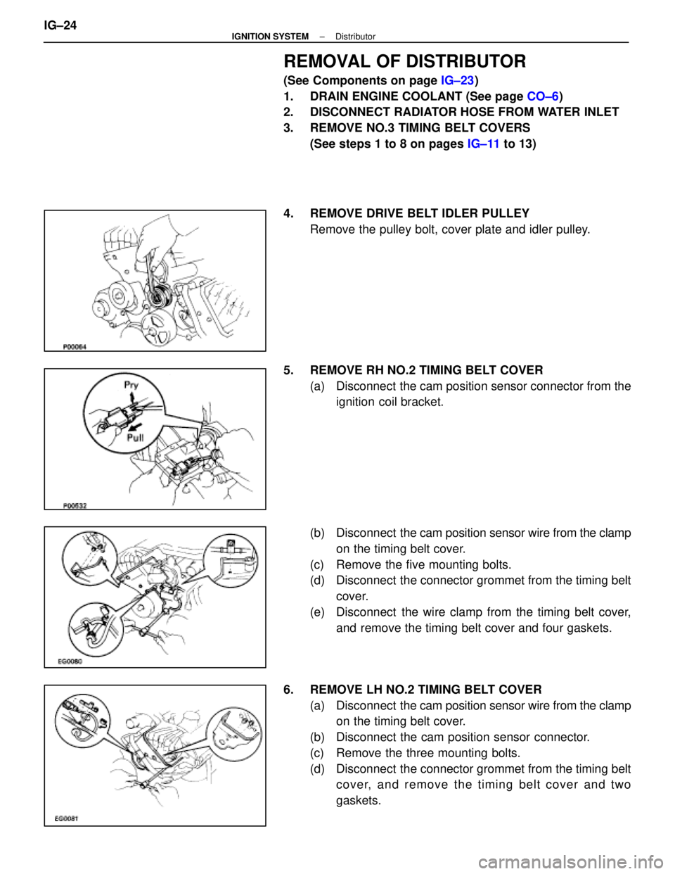
REMOVAL OF DISTRIBUTOR
(See Components on page IG±23)
1. DRAIN ENGINE COOLANT (See page CO±6)
2. DISCONNECT RADIATOR HOSE FROM WATER INLET
3. REMOVE NO.3 TIMING BELT COVERS
(See steps 1 to 8 on pages IG±11 to 13)
4. REMOVE DRIVE BELT IDLER PULLEY Remove the pulley bolt, cover plate and idler pulley.
5. REMOVE RH NO.2 TIMING BELT COVER (a) Disconnect the cam position sensor connector from theignition coil bracket.
(b) Disconnect the cam position sensor wire from the clamp
on the timing belt cover.
(c) Remove the five mounting bolts.
(d) Disconnect the connector grommet from the timing belt cover.
(e) Disconnect the wire clamp from the timing belt cover, and remove the timing belt cover and four gaskets.
6. REMOVE LH NO.2 TIMING BELT COVER (a) Disconnect the cam position sensor wire from the clamp
on the timing belt cover.
(b) Disconnect the cam position sensor connector.
(c) Remove the three mounting bolts.
(d) Disconnect the connector grommet from the timing belt cover, and remove the timing belt cover and two
gaskets.
IG±24
±
IGNITION SYSTEM Distributor
WhereEverybodyKnowsYourName
Page 2547 of 4087
7. DISCONNECT HIGH±TENSION CORDS FROMDISTRIBUTOR CAPS
Disconnect the high±tension cords at the rubber boot. Do not
pull on the cord.
NOTICE: Pulling or bending the cords may damage the
conductor inside.
8. REMOVE DISTRIBUTOR CAPS Loosen the three bolts, and remove the distributor cap. Re-
move the two distributor caps.
HINT: Arrange the distributor caps (RH side and LH side).
9. REMOVE DISTRIBUTOR ROTORS Loosen the two bolts, and remove the distributor rotor. Re-
move the two distributor rotors.
HINT: Arrange the distributor rotors (RH side and LH side).
10. REMOVE DISTRIBUTOR HOUSINGS (a) (RH Distributor Housing)Disconnect the cam position sensor connector.
(b) Re mo ve th e th re e bo lts an d distrib u to r ho u sin g . Remove the two distributor housings.
11. REMOVE CAM POSITION SENSORS FROM DISTRIBUTOR HOUSINGS
Remove the bolt, screw and cam position sensor.
Remove the two cam position sensors.
±
IGNITION SYSTEM DistributorIG±25
WhereEverybodyKnowsYourName
Page 2548 of 4087

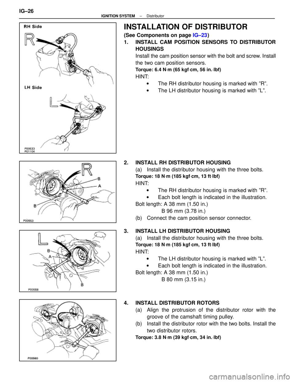
INSTALLATION OF DISTRIBUTOR
(See Components on page IG±23)
1. INSTALL CAM POSITION SENSORS TO DISTRIBUTOR HOUSINGS
Install the cam position sensor with the bolt and screw. Install
the two cam position sensors.
Torque: 6.4 N Vm (65 kgf Vcm, 56 in. Vlbf)
HINT:
w The RH distributor housing is marked with ºRº.
w The LH distributor housing is marked with ºLº.
2. INSTALL RH DISTRIBUTOR HOUSING (a) Install the distributor housing with the three bolts.
Torque: 18 N Vm (185 kgf Vcm, 13 ft Vlbf)
HINT:
w The RH distributor housing is marked with ºRº.
w Each bolt length is indicated in the illustration.
Bolt length: A 38 mm (1.50 in.)
B 96 mm (3.78 in.)
(b) Connect the cam position sensor connector.
3. INSTALL LH DISTRIBUTOR HOUSING (a) Install the distributor housing with the three bolts.
Torque: 18 N Vm (185 kgf Vcm, 13 ft Vlbf)
HINT:
w The LH distributor housing is marked with ºLº.
w Each bolt length is indicated in the illustration.
Bolt length: A 38 mm (1.50 in.)
B 80 mm (3.15 in.)
4. INSTALL DISTRIBUTOR ROTORS (a) Align the protrusion of the distributor rotor with thegroove of the camshaft timing pulley.
(b) Install the distributor rotor with the two bolts. Install the two distributor rotors.
Torque: 3.8 N Vm (39 kgf Vcm, 34 in. Vlbf)
IG±26±
IGNITION SYSTEM Distributor
WhereEverybodyKnowsYourName
Page 2549 of 4087

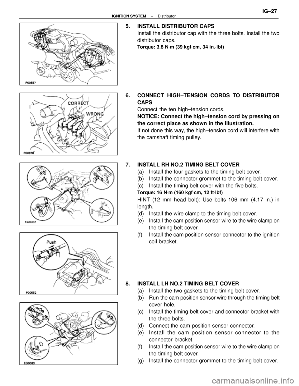
5. INSTALL DISTRIBUTOR CAPSInstall the distributor cap with the three bolts. Install the two
distributor caps.
Torque: 3.8 N Vm (39 kgf Vcm, 34 in. Vlbf)
6. CONNECT HIGH±TENSION CORDS TO DISTRIBUTOR
CAPS
Connect the ten high±tension cords.
NOTICE: Connect the high±tension cord by pressing on
the correct place as shown in the illustration.
If not done this way, the high±tension cord will interfere with
the camshaft timing pulley.
7. INSTALL RH NO.2 TIMING BELT COVER (a) Install the four gaskets to the timing belt cover.
(b) Install the connector grommet to the timing belt cover.
(c) Install the timing belt cover with the five bolts.
Torque: 16 N Vm (160 kgf Vcm, 12 ft Vlbf)
HINT (12 mm head bolt): Use bolts 106 mm (4.17 in.) in
length.
(d) Install the wire clamp to the timing belt cover.
(e) Install the cam position sensor wire to the wire clamp on
the timing belt cover.
(f) Install the cam position sensor connector to the ignition coil bracket.
8. INSTALL LH NO.2 TIMING BELT COVER (a) Install the two gaskets to the timing belt cover.
(b) Run the cam po sition sensor wire through the timing belt
cover hole.
(c) Install the timing belt cover and connector bracket with the three bolts.
(d) Connect the cam position sensor connector.
(e) In sta ll th e ca m po sitio n se n so r c onnector to the
connector bracket.
(f) Install the cam position sensor wire to the wire clamp on
the timing belt cover.
(g) Install the connector grommet to the timing belt cover.
±
IGNITION SYSTEM DistributorIG±27
WhereEverybodyKnowsYourName
Page 2551 of 4087
(c) Check the ignition timing.
Ignition timing: 8±125 BTDC @ idle
(Transmission in neutral range)
If the ignition timing is not as specified, check that following
conditions are normal: w Throttle valve fully closed
w Continuity between terminals IDL1 and E2 of the
throttle position sensor (See page FI±73)
w Valve timing (See page EM±51)
(e) Remove the SST from the check connector.
SST 09843±18020
17. DISCONNECT TACHOMETER AND TIMING LIGHT FROM ENGINE
18. INSTALL UPPER HIGH±TENSION CORD COVER (See step 10 on pages IG±18 and 19)
±
IGNITION SYSTEM DistributorIG±29
WhereEverybodyKnowsYourName
Page 2552 of 4087
ENGINE SPEED SENSOR
COMPONENTS FOR REMOVAL AND
INSTALLATION
REMOVAL OF ENGINE SPEED SENSOR
1. DISCONNECT CABLE FROM NEGATIVE TERMINAL OFBATTERY
CAUTION: Work must be started after approx. 20 se-
conds or longer from the time the ignition switch is
turned to the ºLOCKº position and the negative (±) termi-
nal cable is disconnected from the battery.
2. REMOVE ENGINE UNDER COVER
3. DISCONNECT ENGINE SPEED SENSOR CONNECTOR
4. REMOVE ENGINE SPEED SENSOR Remove the bolt and engine speed sensor.
INSTALLATION OF ENGINE SPEED
SENSOR
1. INSTALL ENGINE SPEED SENSOR
Torque: 6.4 N Vm (65 kgf Vcm, 56 in. Vlbf)
2. CONNECT ENGINE SPEED SENSOR CONNECTOR
3. INSTALL ENGINE UNDER COVER
4. CONNECT CABLE TO NEGATIVE TERMINAL OF
BATTERY
IG±30
±
IGNITION SYSTEM Engine Speed sensor
WhereEverybodyKnowsYourName
Page 2554 of 4087

SERVICE SPECIFICATIONS
SERVICE DATA
Ignition timing8±125 BTDC @ idlegg
(w/ Terminals TE1 and E1 connected)
Firing order1±8±4±3±6±5±7±2
Spark plugTypeNDPK20R11g
NGK BKR6EP11
Electrode gapNew plug STD 1.1 mm 0.043 in.
Used plug Limit 1.3 mm 0.051 in.
High±tensionResistance25 k � per cordg
cord
Ignition coilPrimary coil resistance0.40±0.50 �gy
Secondary coil resistance10.0±14.0 k �
Cam positionResistanceat ±10± +40 5C (14±104 5F)835±1,350 �
sensor
Engine speedResistanceat ±10± +40 5C (14±104 5F)835±1,350 �
sensor
TORQUE SPECIFICATIONS
Part tightenedNVmkgf Vcmft Vlbf
Spark plug X Cylinder head1818013
Cam position sensor X Distributor housing18185 13
Distributor cap X Distributor housing3.839 34 in. Vlbf
Distributor rotor X Camshaft timing pulley3.839 34 in. Vlbf
RH No.2 timing belt cover X Cylinder block (for 12 mm head)16160 12
Drive belt idler pulley X Hydraulic pump37380 27
Engine speed sensor X Oil pump6.46556 in. Vlbf
IG±32±
IGNITION SYSTEM Service Specifications
WhereEverybodyKnowsYourName