Page 2089 of 4087
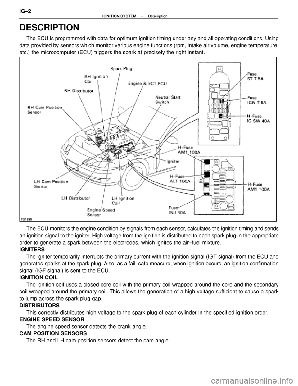
DESCRIPTION
The ECU is programmed with data for optimum ignition timing under any and a\
ll operating conditions. Using
data provided by sensors which monitor various engine functions (rpm, i\
ntake air volume, engine temperature,
etc.) the microcomputer (ECU) triggers the spark at precisely the right ins\
tant.
The ECU monitors the engine condition by signals from each sensor, calculates the ignition timing and sends
an ignition signal to the igniter. High voltage from the ignition is distributed to each spark plug in th\
e appropriate
order to generate a spark between the electrodes, which ignites the air±fu\
el mixture.
IGNITERS The igniter temporarily interrupts the primary current with the ignition si\
gnal (IGT signal) from the ECU and
generates sparks at the spark plug. Also, as a fail±safe measure, when ignitio\
n occurs, an ignition confirmation
signal (IGF signal) is sent to the ECU.
IGNITION COIL
The ignition coil uses a closed core coil with the primary coil wrapped \
around the core and the secondary
coil wrapped around the primary coil. This allows the generation of a hi\
gh voltage sufficient to cause a spark
to jump across the spark plug gap.
DISTRIBUTORS
This correctly distributes high voltage to the spark plug of each cylind\
er in the specified ignition order.
ENGINE SPEED SENSOR The engine speed sensor detects the crank angle.
CAM POSITION SENSORS The RH and LH cam position sensors detect the cam angle.
IG±2
±
IGNITION SYSTEM Description
WhereEverybodyKnowsYourName
Page 2097 of 4087
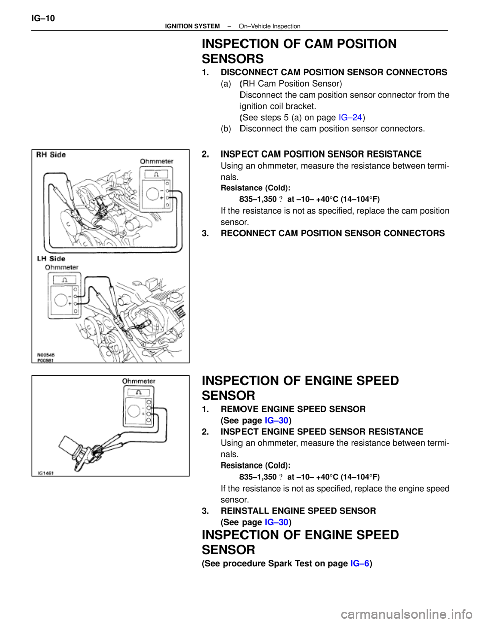
INSPECTION OF CAM POSITION
SENSORS
1. DISCONNECT CAM POSITION SENSOR CONNECTORS(a) (RH Cam Position Sensor)Disconnect the cam position sensor connector from the
ignition coil bracket.
(See steps 5 (a) on page IG±24)
(b) Disconnect the cam position sensor connectors.
2. INSPECT CAM POSITION SENSOR RESISTANCE Using an ohmmeter, measure the resistance between termi-
nals.
Resistance (Cold):
835±1,350 � at ±10± +40 5C (14±104 5F)
If the resistance is not as specified, replace the cam position
sensor.
3. RECONNECT CAM POSITION SENSOR CONNECTORS
INSPECTION OF ENGINE SPEED
SENSOR
1. REMOVE ENGINE SPEED SENSOR (See page IG±30)
2. INSPECT ENGINE SPEED SENSOR RESISTANCE Using an ohmmeter, measure the resistance between termi-
nals.
Resistance (Cold):
835±1,350 � at ±10± +40 5C (14±104 5F)
If the resistance is not as specified, replace the engine speed
sensor.
3. REINSTALL ENGINE SPEED SENSOR (See page IG±30)
INSPECTION OF ENGINE SPEED
SENSOR
(See procedure Spark Test on page IG±6)
IG±10
±
IGNITION SYSTEM On±Vehicle Inspection
WhereEverybodyKnowsYourName
Page 2109 of 4087
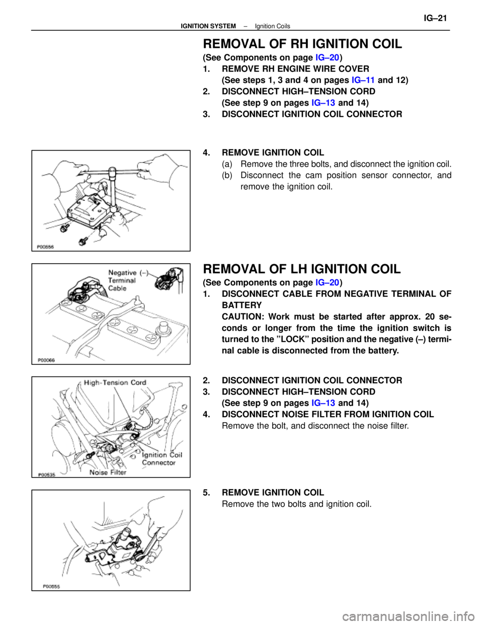
REMOVAL OF RH IGNITION COIL
(See Components on page IG±20)
1. REMOVE RH ENGINE WIRE COVER (See steps 1, 3 and 4 on pages IG±11 and 12)
2. DISCONNECT HIGH±TENSION CORD (See step 9 on pages IG±13 and 14)
3. DISCONNECT IGNITION COIL CONNECTOR
4. REMOVE IGNITION COIL (a) Remove the three bolts, and disconnect the ignition coil.
(b) Disconnect the cam position sensor connector, and
remove the ignition coil.
REMOVAL OF LH IGNITION COIL
(See Components on page IG±20)
1. DISCONNECT CABLE FROM NEGATIVE TERMINAL OF BATTERY
CAUTION: Work must be started after approx. 20 se-
conds or longer from the time the ignition switch is
turned to the ºLOCKº position and the negative (±) termi-
nal cable is disconnected from the battery.
2. DISCONNECT IGNITION COIL CONNECTOR
3. DISCONNECT HIGH±TENSION CORD (See step 9 on pages IG±13 and 14)
4. DISCONNECT NOISE FILTER FROM IGNITION COIL Remove the bolt, and disconnect the noise filter.
5. REMOVE IGNITION COIL Remove the two bolts and ignition coil.
±
IGNITION SYSTEM Ignition CoilsIG±21
WhereEverybodyKnowsYourName
Page 2110 of 4087
INSTALLATION OF RH IGNITION COIL
(See Components on page IG±20)
1. INSTALL IGNITION COIL (a) Install the ignition coil with the three bolts.
(b) Install the cam position sensor connector to the ignition
coil bracket.
2. CONNECT IGNITION COIL CONNECTOR
3. CONNECT HIGH±TENSION CORD
(See step 4 on pages IG±16 and 17)
4. INSTALL RH ENGINE WIRE COVER (See steps 8, 10, 12 and 13 on pages IG±11 and 12)
INSTALLATION OF LH IGNITION COIL
(See Components on page IG±20)
1. INSTALL IGNITION COIL Install the ignition coil with the two bolts.
2. INSTALL NOISE FILTER TO IGNITION COIL Install the noise filter with the bolt.
3. CONNECT HIGH±TENSION CORD
(See step 4 on pages IG±16 and 17)
4. CONNECT IGNITION COIL CONNECTOR
5. CONNECT CABLE TO NEGATIVE TERMINAL OF BATTERY
IG±22
±
IGNITION SYSTEM Ignition Coils
WhereEverybodyKnowsYourName
Page 2112 of 4087
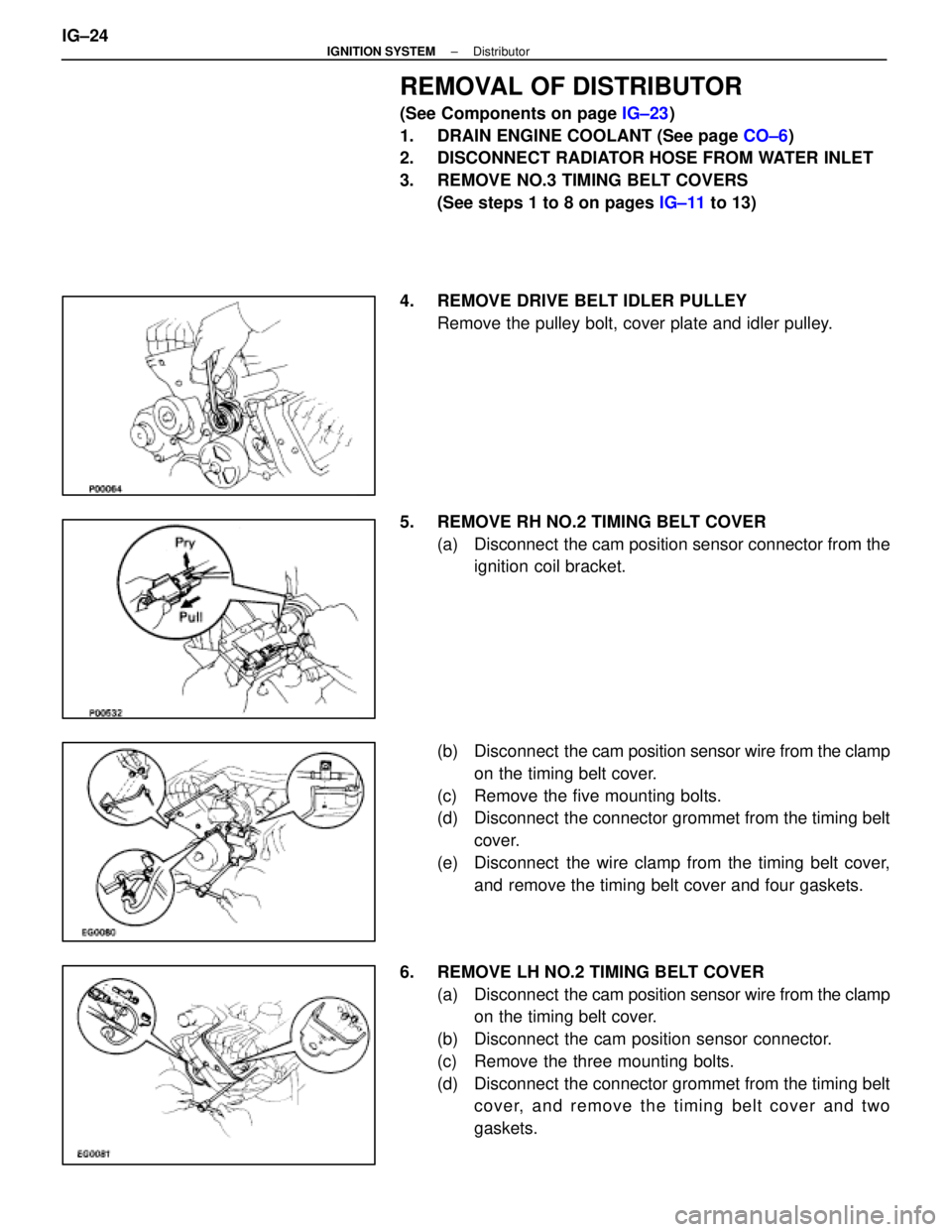
REMOVAL OF DISTRIBUTOR
(See Components on page IG±23)
1. DRAIN ENGINE COOLANT (See page CO±6)
2. DISCONNECT RADIATOR HOSE FROM WATER INLET
3. REMOVE NO.3 TIMING BELT COVERS
(See steps 1 to 8 on pages IG±11 to 13)
4. REMOVE DRIVE BELT IDLER PULLEY Remove the pulley bolt, cover plate and idler pulley.
5. REMOVE RH NO.2 TIMING BELT COVER (a) Disconnect the cam position sensor connector from theignition coil bracket.
(b) Disconnect the cam position sensor wire from the clamp
on the timing belt cover.
(c) Remove the five mounting bolts.
(d) Disconnect the connector grommet from the timing belt cover.
(e) Disconnect the wire clamp from the timing belt cover, and remove the timing belt cover and four gaskets.
6. REMOVE LH NO.2 TIMING BELT COVER (a) Disconnect the cam position sensor wire from the clamp
on the timing belt cover.
(b) Disconnect the cam position sensor connector.
(c) Remove the three mounting bolts.
(d) Disconnect the connector grommet from the timing belt cover, and remove the timing belt cover and two
gaskets.
IG±24
±
IGNITION SYSTEM Distributor
WhereEverybodyKnowsYourName
Page 2113 of 4087
7. DISCONNECT HIGH±TENSION CORDS FROMDISTRIBUTOR CAPS
Disconnect the high±tension cords at the rubber boot. Do not
pull on the cord.
NOTICE: Pulling or bending the cords may damage the
conductor inside.
8. REMOVE DISTRIBUTOR CAPS Loosen the three bolts, and remove the distributor cap. Re-
move the two distributor caps.
HINT: Arrange the distributor caps (RH side and LH side).
9. REMOVE DISTRIBUTOR ROTORS Loosen the two bolts, and remove the distributor rotor. Re-
move the two distributor rotors.
HINT: Arrange the distributor rotors (RH side and LH side).
10. REMOVE DISTRIBUTOR HOUSINGS (a) (RH Distributor Housing)Disconnect the cam position sensor connector.
(b) Re mo ve th e th re e bo lts an d distrib u to r ho u sin g . Remove the two distributor housings.
11. REMOVE CAM POSITION SENSORS FROM DISTRIBUTOR HOUSINGS
Remove the bolt, screw and cam position sensor.
Remove the two cam position sensors.
±
IGNITION SYSTEM DistributorIG±25
WhereEverybodyKnowsYourName
Page 2114 of 4087
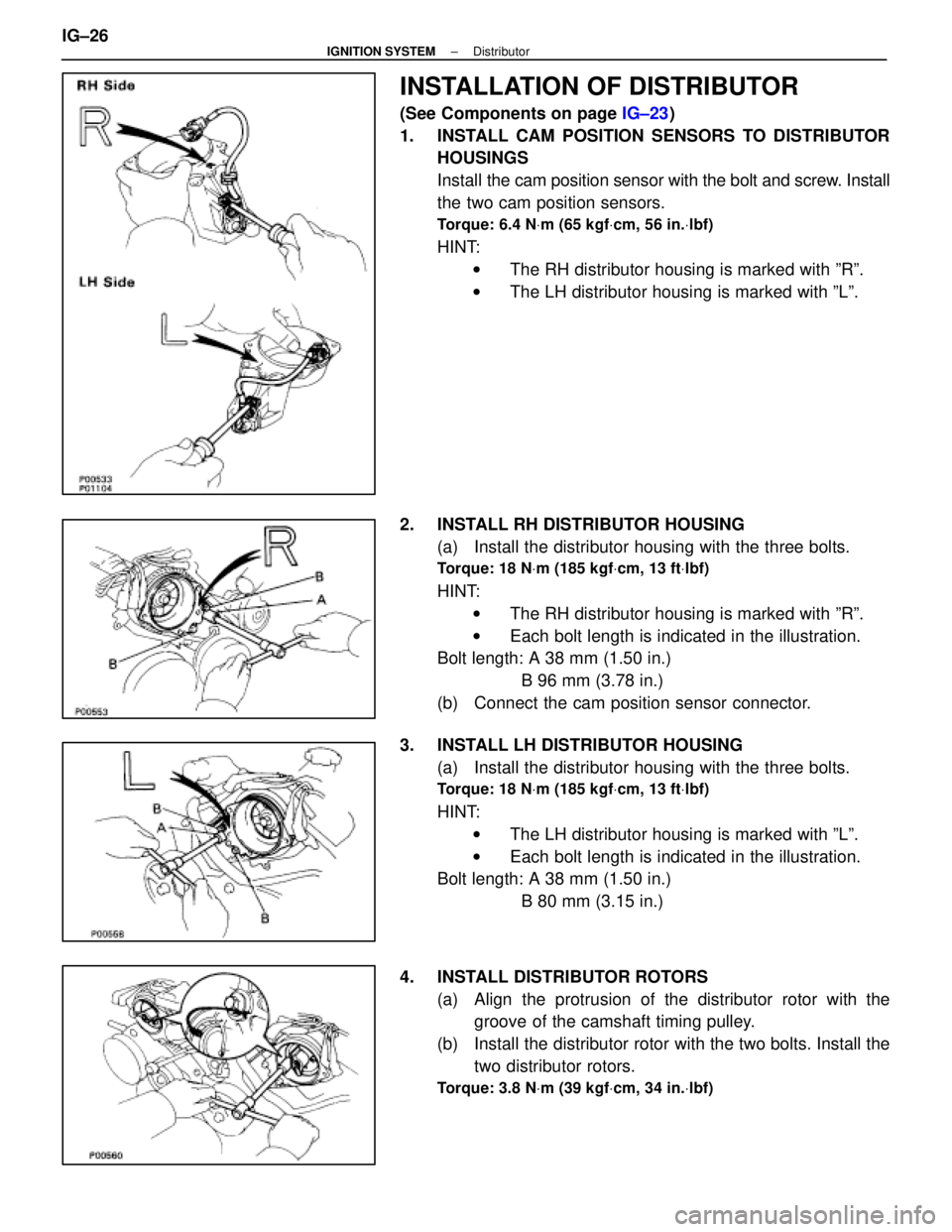
INSTALLATION OF DISTRIBUTOR
(See Components on page IG±23)
1. INSTALL CAM POSITION SENSORS TO DISTRIBUTOR HOUSINGS
Install the cam position sensor with the bolt and screw. Install
the two cam position sensors.
Torque: 6.4 N Vm (65 kgf Vcm, 56 in. Vlbf)
HINT:
w The RH distributor housing is marked with ºRº.
w The LH distributor housing is marked with ºLº.
2. INSTALL RH DISTRIBUTOR HOUSING (a) Install the distributor housing with the three bolts.
Torque: 18 N Vm (185 kgf Vcm, 13 ft Vlbf)
HINT:
w The RH distributor housing is marked with ºRº.
w Each bolt length is indicated in the illustration.
Bolt length: A 38 mm (1.50 in.)
B 96 mm (3.78 in.)
(b) Connect the cam position sensor connector.
3. INSTALL LH DISTRIBUTOR HOUSING (a) Install the distributor housing with the three bolts.
Torque: 18 N Vm (185 kgf Vcm, 13 ft Vlbf)
HINT:
w The LH distributor housing is marked with ºLº.
w Each bolt length is indicated in the illustration.
Bolt length: A 38 mm (1.50 in.)
B 80 mm (3.15 in.)
4. INSTALL DISTRIBUTOR ROTORS (a) Align the protrusion of the distributor rotor with thegroove of the camshaft timing pulley.
(b) Install the distributor rotor with the two bolts. Install the two distributor rotors.
Torque: 3.8 N Vm (39 kgf Vcm, 34 in. Vlbf)
IG±26±
IGNITION SYSTEM Distributor
WhereEverybodyKnowsYourName
Page 2115 of 4087
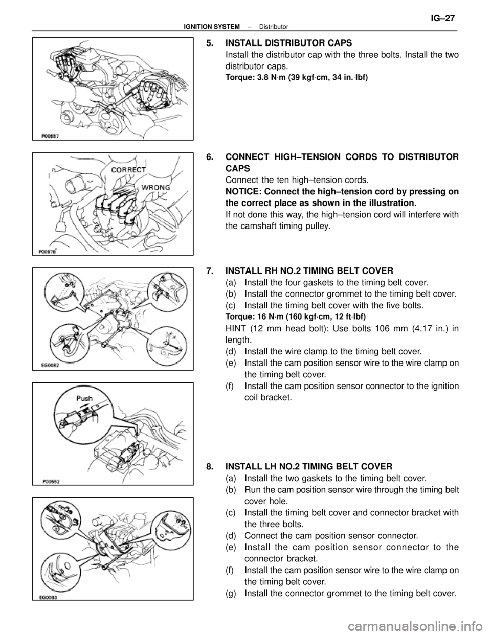
5. INSTALL DISTRIBUTOR CAPSInstall the distributor cap with the three bolts. Install the two
distributor caps.
Torque: 3.8 N Vm (39 kgf Vcm, 34 in. Vlbf)
6. CONNECT HIGH±TENSION CORDS TO DISTRIBUTOR
CAPS
Connect the ten high±tension cords.
NOTICE: Connect the high±tension cord by pressing on
the correct place as shown in the illustration.
If not done this way, the high±tension cord will interfere with
the camshaft timing pulley.
7. INSTALL RH NO.2 TIMING BELT COVER (a) Install the four gaskets to the timing belt cover.
(b) Install the connector grommet to the timing belt cover.
(c) Install the timing belt cover with the five bolts.
Torque: 16 N Vm (160 kgf Vcm, 12 ft Vlbf)
HINT (12 mm head bolt): Use bolts 106 mm (4.17 in.) in
length.
(d) Install the wire clamp to the timing belt cover.
(e) Install the cam position sensor wire to the wire clamp on
the timing belt cover.
(f) Install the cam position sensor connector to the ignition coil bracket.
8. INSTALL LH NO.2 TIMING BELT COVER (a) Install the two gaskets to the timing belt cover.
(b) Run the cam po sition sensor wire through the timing belt
cover hole.
(c) Install the timing belt cover and connector bracket with the three bolts.
(d) Connect the cam position sensor connector.
(e) In sta ll th e ca m po sitio n se n so r c onnector to the
connector bracket.
(f) Install the cam position sensor wire to the wire clamp on
the timing belt cover.
(g) Install the connector grommet to the timing belt cover.
±
IGNITION SYSTEM DistributorIG±27
WhereEverybodyKnowsYourName