Page 1972 of 4087
Sub±Oxygen Sensors
COMPONENTS FOR REMOVAL AND
INSTALLATION
FI±117 ± Electronic Control System (Sub±Oxygen\
Sensors)EFI SYSTEM
WhereEverybodyKnowsYourName
Page 1973 of 4087
 Cancel diagnostic code. (See TR section)
(b) A llo w th e en g in e to wa rm up to no rma l op e ra tin gtemperature.
(c) Drive")
INSPECTION OF SUB±OXYGEN
SENSORS
1. INSPECT SUB±OXYGEN SENSORS(a) Cancel diagnostic code. (See TR section)
(b) A llo w th e en g in e to wa rm up to no rma l op e ra tin gtemperature.
(c) Drive for 5 minutes or more between 80km/h (50 mph) and 100 km/h (62 mph) in ºDº range.
(d) Following the conditions in step (c), press fully on the accelerator pedal for 2 seconds or more.
HINT: Do not exceed 100 km/h (62 mph), or diagnostic code
will be cancelled.
(e) Stop the vehicle, and turn the ignition switch to OFF.
(f) Carry out steps (b), (c) and (d) again to test acceleration.
If code No.27 reappears again, check the sub±oxygen sen-
sor circuit. If the circuit is normal, replace the sub±oxygen
sensor.
2. DISCONNECT CABLE FROM NEGATIVE TERMINAL OF BATTERY
CAUTION: Work must be started after approx. 20 se-
conds or longer from the time the ignition switch is
turned to the ºLOCKº position and the negative (±) termi-
nal cable is disconnected from the battery.
3. REMOVE TRANSMISSION SHIFT LEVER KNOB (a) Push down the lever cover.
(b) Remove the two screws and shift lever knob.
(c) Remove the lever cover.
FI±118
EFI SYSTEM
± Electronic Control System (Sub±Oxygen Sensors)
WhereEverybodyKnowsYourName
Page 1974 of 4087
4. REMOVE CUP HOLDERUsing a screwdriver, pry out the rear side of the cup holder.
Remove the cup holder.
5. REMOVE UPPER REAR CONSOLE PANEL Using a screwdriver, pry out the console panel.
6. REMOVE UPPER CONSOLE PANEL (a) Remove the six mounting screws.
(b) Using a screwdriver, pry out the console panel.
7. REMOVE RADIO (a) Remove the five mounting bolts.
(b) Disconnect the wiring connectors and antenna cable,
and remove the radio.
8. DISCONNECT SUB±OXYGEN SENSOR CONNECTORS FI±119
EFI SYSTEM
± Electronic Control System (Sub±Oxygen Sensors)
WhereEverybodyKnowsYourName
Page 1975 of 4087
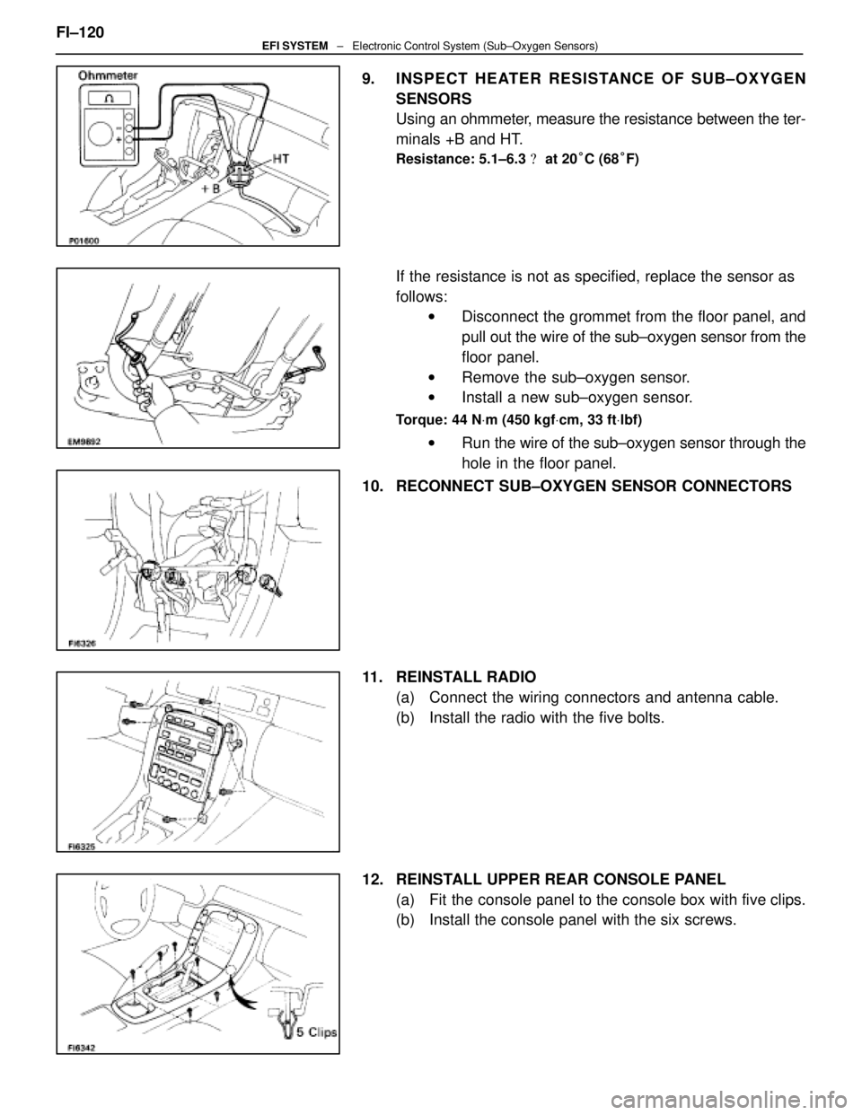
9. INSPECT HEATER RESISTANCE OF SUB±OXYGEN
SENSORS
Using an ohmmeter, measure the resistance between the ter-
minals +B and HT.
Resistance: 5.1±6.3 � at 20 °C (68 °F)
If the resistance is not as specified, replace the sensor as
follows:
w Disconnect the grommet from the floor panel, and
pull out the wire of the sub±oxygen sensor from the
floor panel.
w Remove the sub±oxygen sensor.
w Install a new sub±oxygen sensor.
Torque: 44 N Vm (450 kgf Vcm, 33 ft Vlbf)
w Run the wire of the sub±oxygen sensor through the
hole in the floor panel.
10. RECONNECT SUB±OXYGEN SENSOR CONNECTORS
11. REINSTALL RADIO (a) Connect the wiring connectors and antenna cable.
(b) Install the radio with the five bolts.
12. REINSTALL UPPER REAR CONSOLE PANEL (a) Fit the console panel to the console box with five clips.
(b) Install the console panel with the six screws.
FI±120
EFI SYSTEM
± Electronic Control System (Sub±Oxygen Sensors)
WhereEverybodyKnowsYourName
Page 1976 of 4087
13. REINSTALL UPPER CONSOLE PANELFit the console panel to the console box with the four clips.
14. REINSTALL CUP HOLDER Fit the cup holder to the console box.
15. REINSTALL TRANSMISSION SHIFT LEVER KNOB (a) Slide the lever cover on the lever shaft.
(b) Install the shift lever knob with the two screws.
(c) Attach the l ever cover to the lower side of the lever knob.
16. RECONNECT CABLE TO NEGATIVE TERMINAL OF BATTERY FI±121
EFI SYSTEM
± Electronic Control System (Sub±Oxygen Sensors)
WhereEverybodyKnowsYourName
Page 1977 of 4087
Preparation
SST (SPECIAL SERVICE TOOLS)
IllustrationPart No.Part NameNote
09268±41045Injection Measuring
Tool Set
(90268±41070)No. 4 Union
Injector
(09268±41080)No. 6 Union
Cold start Injector
(09268±52010)Injection Measuring
Attachment
Injector
09268±45012EFI Fuel Pressure
Gauge
09612±24014
Steering Gear
Housing Overhaul
Tool Set
(09617±24011)Steering Rack Wrench
Fuel pressure pulsation damper
09631±22020
Power Steering
Hose Nut 14 X 17 mm
Wrench SetFuel line flare nut
09816±30010Oil Pressure
Switch SocketKnock sensor
09842±30055Wire ªGº
EFI Inspection
Cold start Injector
09842±30070Wire ªFº
EFI Inspection
Injector
09843±18020Diagnosis Check
Wire
0990±01000
Engine Control
Computer
Check Harness ªAº
FI±10 ± PreparationEFI SYSTEM
WhereEverybodyKnowsYourName
Page 1983 of 4087

Engine & ECT ECU
TERMINALS OF ENGINE & ECT ECU
TerminalNo.SymbolConnectionTerminalNo.SymbolConnection
E9 ± 1IGSWIgnition SwitchE9 ± 31+ BEFI Main Relay
2SPDNo. 1 Speed Sensor32+ B1EFI Main Relay
3KDKick±Down Switch33BATTBattery
4STPStop light Switch34A/CA/C Control Assembly
5±35±
6WªCHECKº Engine Warning Light36±
7RNeutral Start Switch37TRTRAC ECU
8±38NEOTRAC ECU
92Neutral Start Switch39VTO2TRAC ECU
10LNeutral Start Switch40VTO1TRAC ECU
11ADCC ECUE10 ± 1NCO �T/M Input Speed Sensor
12OD1CC ECU2±
13±3SP2�No. 2 Speed Sensor for ECT
14±4E11ECU Ground
15±5G2�Cam position Sensor
16±6G1�Cam position Sensor
17TTTDCL7NF�Engine Speed Sensor
18PECT Pattern Select Switch8±
19TE2Check Connector9S2ECT Solenoid Value
20TE1Check Connector10S1ECT Solenoid Value
21D1Fuel Pump ECU11±
22FPCFuel Pump ECU12±
23ACMGA/C Magnet Clutch Relay13SLN �No.3 ECT Solenoid Valve
24M±RELEFI Main Relay14SLU�No.4 ECT Solenoid Valve
25±15±
26±16±
27±17#10No.3 and No.5 Injectors
28OD2O/D Main Relay18#20No.4 and No.6 Injectors
29±19#20No.2 and No.8 Injectors
30±20#40No.1 and No.7 Injectors
Engine & ECT ECU Terminals
FI±126 ± Electronic Control \
System (Engine & ECT ECU)EFI SYSTEM
WhereEverybodyKnowsYourName
Page 1984 of 4087

TerminalNo.SymbolConnectionTerminalNo.SymbolConnection
E10± 21NCOT/M Input Speed SensorE10 ± 51±
22±52HTL2LH Sub±Oxygen Sensor Heater
23SP2No.2 Speed Senso")
TERMINALS OF ENGINE & ECT ECU (Cont'd)
TerminalNo.SymbolConnectionTerminalNo.SymbolConnection
E10± 21NCOT/M Input Speed SensorE10 ± 51±
22±52HTL2LH Sub±Oxygen Sensor Heater
23SP2No.2 Speed Sensor for ECT53HTR2RH Sub±Oxygen Sensor Heater
24±54±
25G2LH (No.2) Cam Position Sensor55±
26G1RH (No.1) Cam Position Sensor56IGT2No.2 Igniter for RH Bank
27NEEngine Speed Sensor57IGT1No.1 Igniter for LH Bank
28VF2Check Connector58IGF1No.1 Igniter for LH Bank
29VF1Check Connector59IGF2No.2 Igniter for RH Bank
30±60±
31±61±
32ISC4ISC Valve62±
33ISC3ISC Valve63IDL2Sub±Throttle Position Sensor
34ISC2ISC Valve64IDL1Throttle Position Sensor
35ISC1ISC Valve65E2Sensor Ground
36*� EGR4EGR Valve66KSAir Flow Meter
37*� EGR3EGR Valve67OXR2
38*� EGR2EGR Valve68OXL2LH Sub±Oxygen Sensor
39*� EGR1EGR Valve69E1ECU Ground39*� EGRVSV for EGR69E1ECU Ground
40±70±
41VCThrottle Position Sensor
Air Flow Meter71HTL1LH Main Oxygen Sensor
42VTA2Fuel Pump ECU72HTR1RH Main Oxygen Sensor
43VTA1A/C Magnet Clutch Relay73FPUVSV for Fuel Pressure Control
Value
44THWWater Temp. Sensor74*� PA GVSV for EVAP
45THAIntake Air Temp. Sensor75±
46THGEGR Gas Temp. Sensor76NSWNeutral Start Switch
47OXR1RH Main Oxygen Sensor77STAStarter Relay
48OXL1LH Main Oxygen Sensor78STJCold Start Injector
49KNK2RH (No.2) Knock Sensor79E02Power Ground
50KNK1LH (No.1) Knock Sensor80E01Power Ground
Engine & ECT ECU Terminals
*��USA spec. only
* �� A/T only
FI±127EFI SYSTEM ± Electronic Control System (Engine & ECT ECU)
WhereEverybodyKnowsYourName
EFI SYSTEM
WhereEverybodyKnowsYourName")


IllustrationPart No.Part NameNote
09268±41045Injection Measuring
Tool Set
(90268±41070)No. 4 Union
Injector
(09268±41080)No. 6 Union
Cold start Injector
(09")