Page 1956 of 4087
(e) Push in the water inlet housing end into the water pumphole.
(f) Install the water inlet and inlet housing assembly with
the two bolts. Alternately tighten the bolts.
Torque: 18 N Vm (185 kgf Vcm, 13 ft Vlbf)
(g) Connect the water by±pass hose to the water inlet
housing.
9. RECONNECT HOSES Connect the following hoses:(1) Upper radiator hose to front water by±pass joint
(2) Lower radiator hose to water inlet
(3) Radiator reservoir hose to front water inlet housing
10. REINSTALL RH IGNITION COIL (a) Install the ignition coil with the two bolts.
(b) Install the cam position sensor connector to the ignitioncoil bracket.
(c) Connect the ignition coil connector.
11. REINSTALL LOWER HIGH±TENSION CORD COVER (See steps 1 to 13 and 16 to 18 on pages FI±39 to 41)FI±101
EFI SYSTEM
± Electronic Control System (Water Temperature Sensor)
WhereEverybodyKnowsYourName
Page 1957 of 4087
EGR Gas Temperature Sensor (USA Spec. only)
COMPONENTS FOR REMOVAL AND INSTALLATION
FI±102 ± Electronic Control System (EGR Gas \
Temperature Sensor (USA Spec. only))EFI SYSTEM
WhereEverybodyKnowsYourName
Page 1958 of 4087
INSPECTION OF EGR GAS
TEMPERATURE SENSOR
1. DISCONNECT CABLE FROM NEGATIVE TERMINAL OFBATTERY
CAUTION: Work must be started after approx. 20 se-
conds or longer from the time the ignition switch is
turned to the ºLOCKº position and the negative (±) termi-
nal cable is disconnected from the battery.
2. DRAIN ENGINE COOLANT
3. REMOVE EGR VALVE (a) Disconnect the EGR gas temperature sensor.
(b) Disconnect the following hoses from the EGR valve:(1) Water by±pass hose (from ISC valve)
(2) Water by±pass hose (from rear water by±pass joint)
(c) Remove the two nuts, EGR valve and gasket.
4. REMOVE EGR VALVE ADAPTOR (a) Disconnect the EGR gas temperature sensor.
(b) Disconnect the PCV hose from the EGR valve adaptor.
(c) Remove the two bolts, two nuts, EGR valve adaptor andgasket. FI±103
EFI SYSTEM
± Electronic Control System (EGR Gas Temperature Sensor (USA Spec. only))
WhereEverybodyKnowsYourName
Page 1959 of 4087

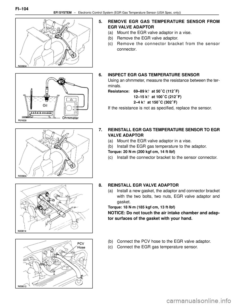
5. REMOVE EGR GAS TEMPERATURE SENSOR FROMEGR VALVE ADAPTOR
(a) Mount the EGR valve adaptor in a vise.
(b) Remove the EGR valve adaptor.
(c) R e m o v e t h e c onnector bracket from the sensor
connector.
6. INSPECT EGR GAS TEMPERATURE SENSOR Using an ohmmeter, measure the resistance between the ter-
minals.
Resistance: 69±89 k � at 50 °C (112 °F)
12±15 k � at 100 °C (212 °F)
2±4 k � at 150 °C (302 °F)
If the resistance is not as specified, replace the sensor.
7. REINSTALL EGR GAS TEMPERATURE SENSOR TO EGR VALVE ADAPTOR
(a) Mount the EGR valve adaptor in a vise.
(b) Install the EGR gas temperature to the adaptor.
Torque: 20 N Vm (200 kgf Vcm, 14 ft Vlbf)
(c) Install the connector bracket to the sensor connector.
8. REINSTALL EGR VALVE ADAPTOR (a) Install a new gasket, the adaptor and connector bracketwith the two bolts, two nuts, EGR valve adaptor and
gasket.
Torque: 18 N Vm (185 kgf Vcm, 13 ft Vlbf)
NOTICE: Do not touch the air intake chamber and adap-
tor surfaces of the gasket with your hand.
(b) Connect the PCV hose to the EGR valve adaptor.
(c) Connect the EGR gas temperature sensor.
FI±104
EFI SYSTEM
± Electronic Control System (EGR Gas Temperature Sensor (USA Spec. only))
WhereEverybodyKnowsYourName
Page 1960 of 4087
9. REINSTALL EGR VALVE(a) Place a new gasket on the EGR valve adaptor.
NOTICE:
w Do not touch the adaptor and EGR valve surfaces of the
gasket with your hand.
w Align the port holes of the gasket and adaptor. Be careful
of the installation direction.
(b) Install the EGR valve with the two nuts.
Torque: 18 N Vm (185 kgf Vcm, 13 ft Vlbf)
(c) Connect the following hoses to the EGR valve:
(1) Water by±pass hose (from ISC valve)
(2) Water by±pass hose (from rear water by±pass joint)
(d) Connect the EGR gas temperature sensor.
10. RECONNECT CABLE FROM NEGATIVE TERMINAL OF BATTERY
11. REFILL WITH ENGINE COOLANT FI±105
EFI SYSTEM
± Electronic Control System (EGR Gas Temperature Sensor (USA Spec. only))
WhereEverybodyKnowsYourName
Page 1961 of 4087
Knock Sensors
FI±106 ± Electronic Control System (Knock \
Sensors)EFI SYSTEM
WhereEverybodyKnowsYourName
Page 1962 of 4087
COMPONENTS FOR REMOVAL AND INSTALLATION
FI±107EFI SYSTEM ± Electronic Control System (Knock Sensors)
WhereEverybodyKnowsYourName
Page 1963 of 4087

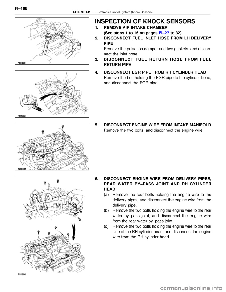
INSPECTION OF KNOCK SENSORS
1. REMOVE AIR INTAKE CHAMBER(See steps 1 to 16 on pages FI±27 to 32)
2. DISCONNECT FUEL INLET HOSE FROM LH DELIVERY PIPE
Remove the pulsation damper and two gaskets, and discon-
nect the inlet hose.
3. DISCONNECT FUEL RETURN HOSE FROM FUEL RETURN PIPE
4. DISCONNECT EGR PIPE FROM RH CYLINDER HEAD Remove the bolt holding the EGR pipe to the cylinder head,
and disconnect the EGR pipe.
5. DISCONNECT ENGINE WIRE FROM INTAKE MANIFOLD Remove the two bolts, and disconnect the engine wire.
6. DISCONNECT ENGINE WIRE FROM DELIVERY PIPES, REAR WATER BY±PASS JOINT AND RH CYLINDER
HEAD
(a) Remove the four bolts holding the engine wire to thedelivery pipes, and disconnect the engine wire from the
delivery pipe.
(b) Remove the two bolts holding the engine wire to the rear
water by±pass joint, and disconnect the engine wire
from the rear water by±pass joint.
(c) Remove the two bolts holding the engine wire to the rear
side of the RH cylinder head, and disconnect the engine
wire from the RH cylinder head.
FI±108
EFI SYSTEM
± Electronic Control System (Knock Sensors)
WhereEverybodyKnowsYourName