Page 1920 of 4087
2. REMOVE KNOCK SENSOR(a) Disconnect the knock sensor connectors.
(b) Using SST, remove the two knock sensors.
SST 09816±30010
3. INSPECT KNOCK SENSOR Using an ohmmeter, check that there is no continuity be-
tween the terminal and body.
If there is continuity, replace the sensor.
4. REINSTALL KNOCK SENSOR (a) Using SST, remove the two knock sensors.
SST 09816±30010
Torque: 44 N Vm (450 kgf Vcm, 33 ft Vlbf)
(b) Connect the knock sensor connectors.
5. RECONNECT CABLE FROM NEGATIVE TERMINAL OF BATTERY
FI±70
±
EFI SYSTEM Electronic Control System (Knock Sensors)
WhereEverybodyKnowsYourName
Page 1921 of 4087
EGR Gas Temperature Sensor (USA Spec. only)
INSPECTION OF EGR GAS
TEMPERATURE SENSOR
1. DISCONNECT CABLE FROM NEGATIVE TERMINAL OFBATTERY
CAUTION: Turn the ignition switch to ºLOCKº. Discon-
nect the cable from the negative (±) terminal of the bat-
tery. Wait at least 20 seconds before proceeding with
work.
2. REMOVE EGR GAS TEMPERATURE SENSOR (a) D i s c onnect the EGR gas temperature sensor
connector.
(b) Remove the EGR gas temperature sensor and gasket.
3. INSPECT EGR GAS TEMPERATURE SENSOR Using an ohmmeter, measure the resistance between the ter-
minals.
Resistance: 69±89 k � at 50 5C (112 5F)
12±15 k � at 100 5C (212 5F)
2±4 k � at 150 5C (302 5F)
If the resistance is not as specified, replace the sensor.
±
EFI SYSTEM Electronic Control System (EGR Gas Temperature
Sensor (USA Spec. only)FI±71
WhereEverybodyKnowsYourName
Page 1922 of 4087
4. REINSTALL EGR GAS TEMPERATURE SENSOR(a) Install a gasket and the EGR gas temperature sensor.
Torque: 20 N Vm (200 kgf Vcm, 14 ft Vlbf)
(b) Connect the EGR gas temperature sensor connector.
5. RECONNECT CABLE FROM NEGATIVE TERMINAL OF BATTERY
FI±72
±
EFI SYSTEM Electronic Control System (EGR Gas Temperature
Sensor (USA Spec. only)
WhereEverybodyKnowsYourName
Page 1923 of 4087
Main Oxygen Sensors
INSPECTION OF MAIN OXYGEN
SENSORS
1. WARM UP ENGINEAllow the engine to warm up to normal operating tempera-
ture.
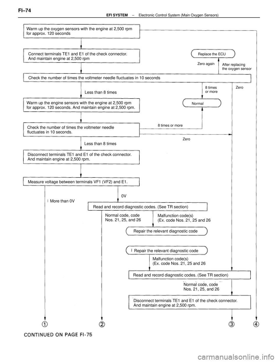
2. INSPECT FEEDBACK VOLTAGE Connect the positive (+) probe of a voltmeter to terminal VF1
(for No.1) or VF2 (for No.2) of the check (ºDIAGNOSISº) con-\
nector, and negative (±) probe to terminal E1. Perform the
test as follows described on the next page.
HINT: Use SST when connecting between terminals TE1 and
E1 of the check connector.
SST 09843±18020
±
EFI SYSTEM Electronic Control System (Main Oxygen Sensors)FI±73
WhereEverybodyKnowsYourName
Page 1924 of 4087

Replace the ECU
Zero againAfter replacing
the oxygen sensor
Normal
8 times
or moreZero
Check the number of times the voltmeter needle fluctuates in 10 seconds
Zero
8 times or more
Warm up the oxygen sensors with the engine at 2,500 rpm
for approx. 120 seconds
Connect terminals TE1 and E1 of the check connector.
And maintain engine at 2,500 rpm
Warm up the engine sensors with the engine at 2,500 rpm
for approx. 120 seconds. And maintain engine at 2,500 rpm.
Check the number of times the voltmeter needle
fluctuates in 10 seconds.
Less than 8 times
Disconnect terminals TE1 and E1 of the check connector.
And maintain engine at 2,500 rpm.
Measure voltage between terminals VF1 (VF2) and E1.
Less than 8 times
More than 0V
0V
Normal code, code
Nos. 21, 25, and 26Malfunction code(s)
(Ex. code Nos. 21, 25 and 26
Read and record diagnostic codes. (See TR section)
Repair the relevant diagnostic code
Disconnect terminals TE1 and E1 of the check connector.
And maintain engine at 2,500 rpm.
Read and record diagnostic codes. (See TR section)
Malfunction code(s)
(Ex. code Nos. 21, 25 and 26
Normal code, code
Nos. 21, 25, and 26
Repair the relevant diagnostic code
FI±74±
EFI SYSTEM Electronic Control System (Main Oxygen Sensors)
WhereEverybodyKnowsYourName
Page 1925 of 4087
Measure voltage between terminals VF1 (VF2) and E1.
Disconnect terminals TE1 and E1 of the check connector.
And maintain engine at 2,500 rpm.
Measure voltage between terminals VF1 (VF2) and E1.
Disconnect the PCV hose.
0V
5V
More than 0V
Repair (Over rich)
Disconnect the water temp. sensor connector and connect
resistor with a resistance of 4 ± 8 kW or another coded water
temp. sensor.
Connect terminals TE1 and E1 of the check connector.
Warm up the oxygen sensors with the engine at 2,500 rpm for
approx. 120 seconds, and maintain engine at 2,500 rpm
Measure voltage between terminals VF1 (VF2) and E1.
Replace the oxygen sensor.Repair (Over lean)
5V
0V
±
EFI SYSTEM Electronic Control System (Main Oxygen Sensors)FI±75
WhereEverybodyKnowsYourName
Page 1926 of 4087
Sub±Oxygen Sensor (USA Spec. only)
COMPONENTS FOR REMOVAL AND
INSTALLATION
FI±76±
EFI SYSTEM Electronic Control System (Sub±Oxygen Sensor (USA Spec. only))
WhereEverybodyKnowsYourName
Page 1927 of 4087

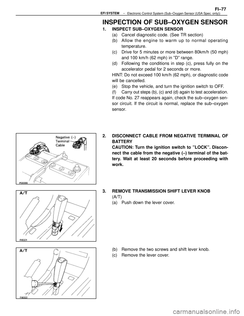
INSPECTION OF SUB±OXYGEN SENSOR
1. INSPECT SUB±OXYGEN SENSOR(a) Cancel diagnostic code. (See TR section)
(b) A llo w th e en g in e to wa rm up to no rma l op e ra tin gtemperature.
(c) Drive for 5 minutes or more between 80km/h (50 mph) and 100 km/h (62 mph) in ºDº range.
(d) Following the conditions in step (c), press fully on the
accelerator pedal for 2 seconds or more.
HINT: Do not exceed 100 km/h (62 mph), or diagnostic code
will be cancelled.
(e) Stop the vehicle, and turn the ignition switch to OFF.
(f) Carry out steps (b), (c) and (d) again to test acceleration.
If code No. 27 reappears again, check the sub±oxygen sen-
sor circuit. If the circuit is normal, replace the sub±oxygen
sensor.
2. DISCONNECT CABLE FROM NEGATIVE TERMINAL OF BATTERY
CAUTION: Turn the ignition switch to ºLOCKº. Discon-
nect the cable from the negative (±) terminal of the bat-
tery. Wait at least 20 seconds before proceeding with
work.
3. REMOVE TRANSMISSION SHIFT LEVER KNOB (A/T)
(a) Push down the lever cover.
(b) Remove the two screws and shift lever knob.
(c) Remove the lever cover.
±
EFI SYSTEMFI±77Electronic Control System (Sub±Oxygen Sensor (USA Spec. only))
WhereEverybodyKnowsYourName