Page 1720 of 4087
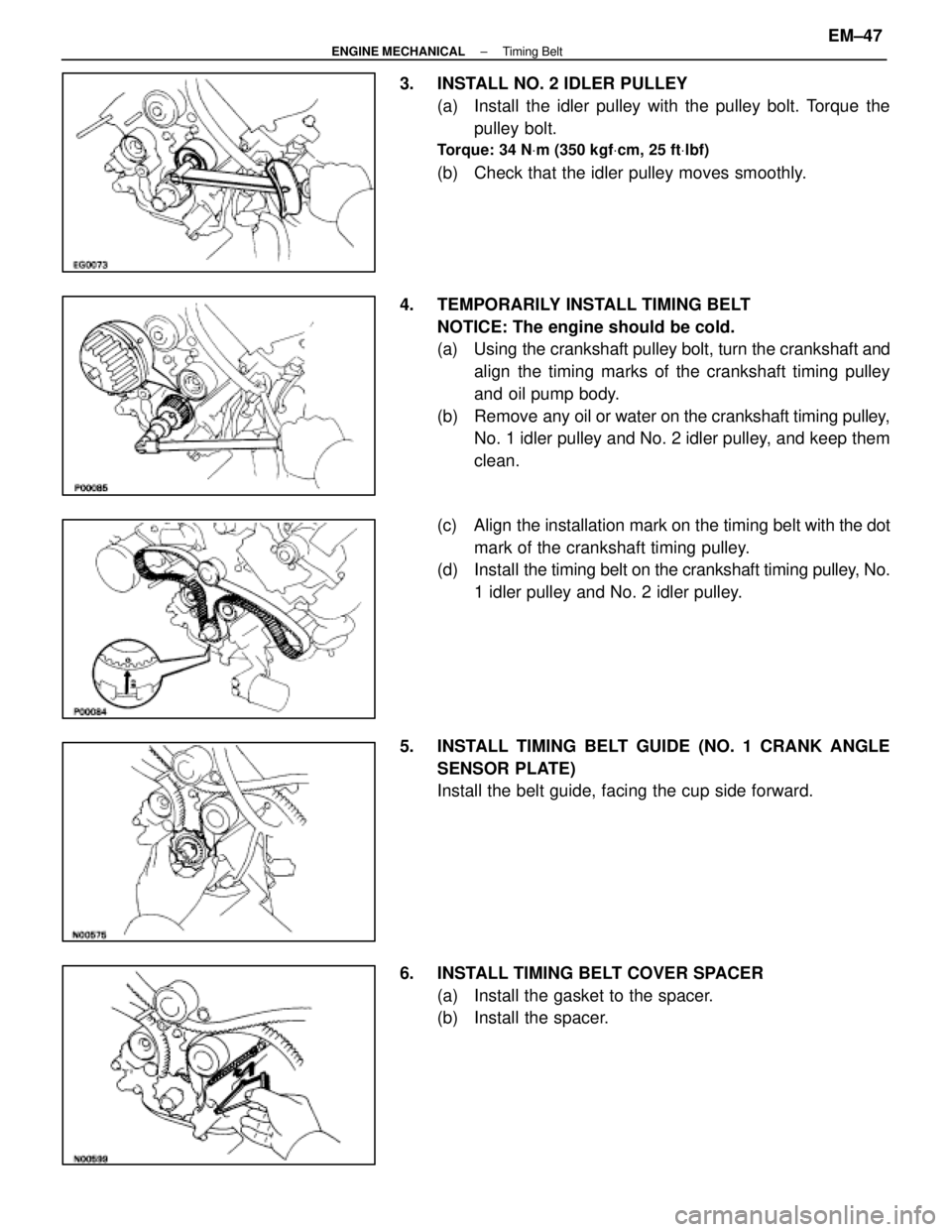
3. INSTALL NO. 2 IDLER PULLEY(a) Install the idler pulley with the pulley bolt. Torque thepulley bolt.
Torque: 34 N Vm (350 kgf Vcm, 25 ft Vlbf)
(b) Check that the idler pulley moves smoothly.
4. TEMPORARILY INSTALL TIMING BELT NOTICE: The engine should be cold.
(a) Using the crankshaft pulley bolt, turn the crankshaft andalign the timing marks of the crankshaft timing pulley
and oil pump body.
(b) Remove any oil or water on the crankshaft timing pulley,
No. 1 idler pulley and No. 2 idler pulley, and keep them
clean.
(c) Align the installation mark on the timing belt with the dot
mark of the crankshaft timing pulley.
(d) Install the timing belt on the crankshaft timing pulley, No.
1 idler pulley and No. 2 idler pulley.
5. INSTALL TIMING BELT GUIDE (NO. 1 CRANK ANGLE SENSOR PLATE)
Install the belt guide, facing the cup side forward.
6. INSTALL TIMING BELT COVER SPACER (a) Install the gasket to the spacer.
(b) Install the spacer.
±
ENGINE MECHANICAL Timing BeltEM±47
WhereEverybodyKnowsYourName
Page 1721 of 4087
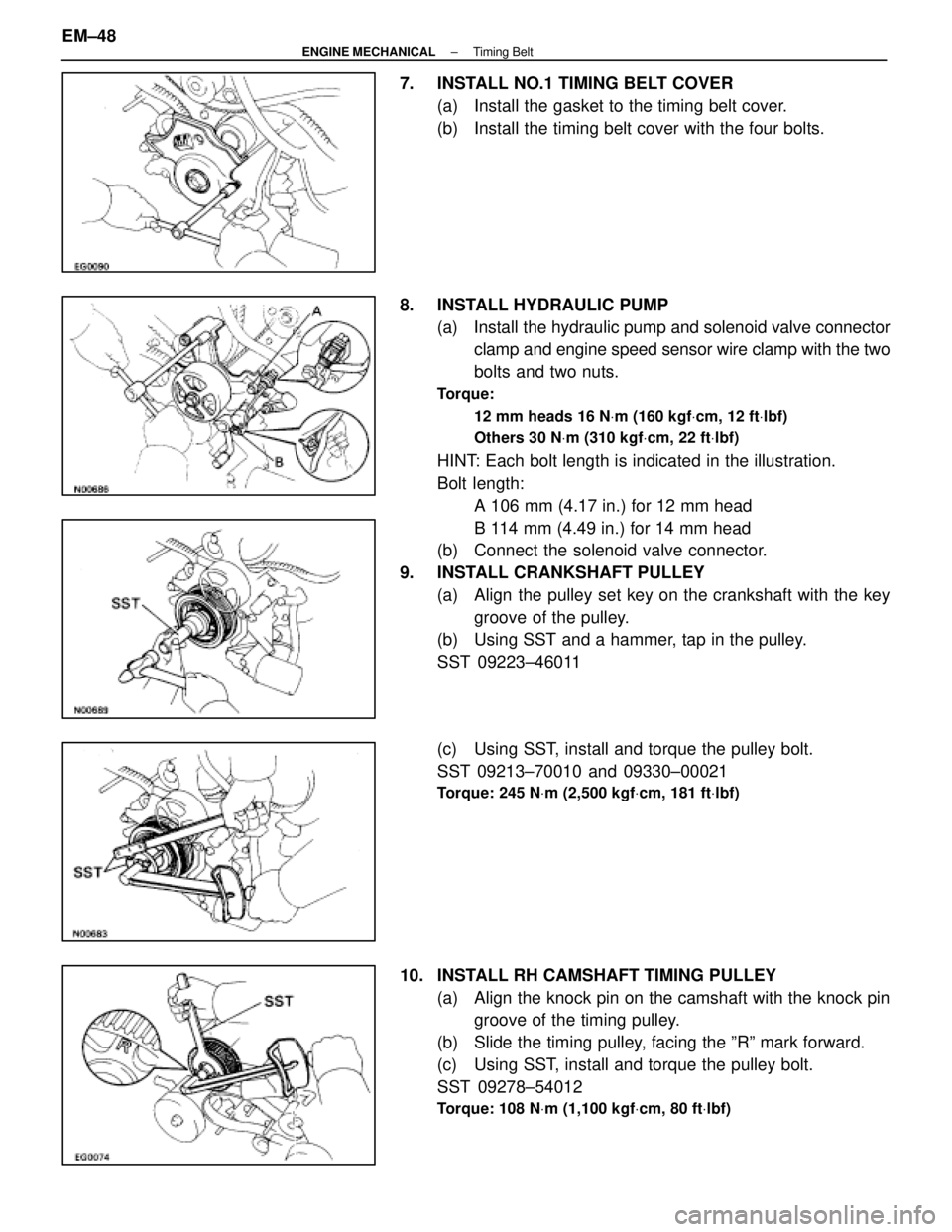
7. INSTALL NO.1 TIMING BELT COVER(a) Install the gasket to the timing belt cover.
(b) Install the timing belt cover with the four bolts.
8. INSTALL HYDRAULIC PUMP (a) Install the hydraulic pump and solenoid valve connectorclamp and engine speed sensor wire clamp with the two
bolts and two nuts.
Torque:
12 mm heads 16 N Vm (160 kgf Vcm, 12 ft Vlbf)
Others 30 N Vm (310 kgf Vcm, 22 ft Vlbf)
HINT: Each bolt length is indicated in the illustration.
Bolt length:
A 106 mm (4.17 in.) for 12 mm head
B 114 mm (4.49 in.) for 14 mm head
(b) Connect the solenoid valve connector.
9. INSTALL CRANKSHAFT PULLEY (a) Align the pulley set key on the crankshaft with the keygroove of the pulley.
(b) Using SST and a hammer, tap in the pulley.
SST 09223±46011
(c) Using SST, install and torque the pulley bolt.
SST 09213±70010 and 09330±00021
Torque: 245 N Vm (2,500 kgf Vcm, 181 ft Vlbf)
10. INSTALL RH CAMSHAFT TIMING PULLEY
(a) Align the knock pin on the camshaft with the knock pingroove of the timing pulley.
(b) Slide the timing pulley, facing the ºRº mark forward.
(c) Using SST, install and torque the pulley bolt.
SST 09278±54012
Torque: 108 N Vm (1,100 kgf Vcm, 80 ft Vlbf)
EM±48±
ENGINE MECHANICAL Timing Belt
WhereEverybodyKnowsYourName
Page 1725 of 4087
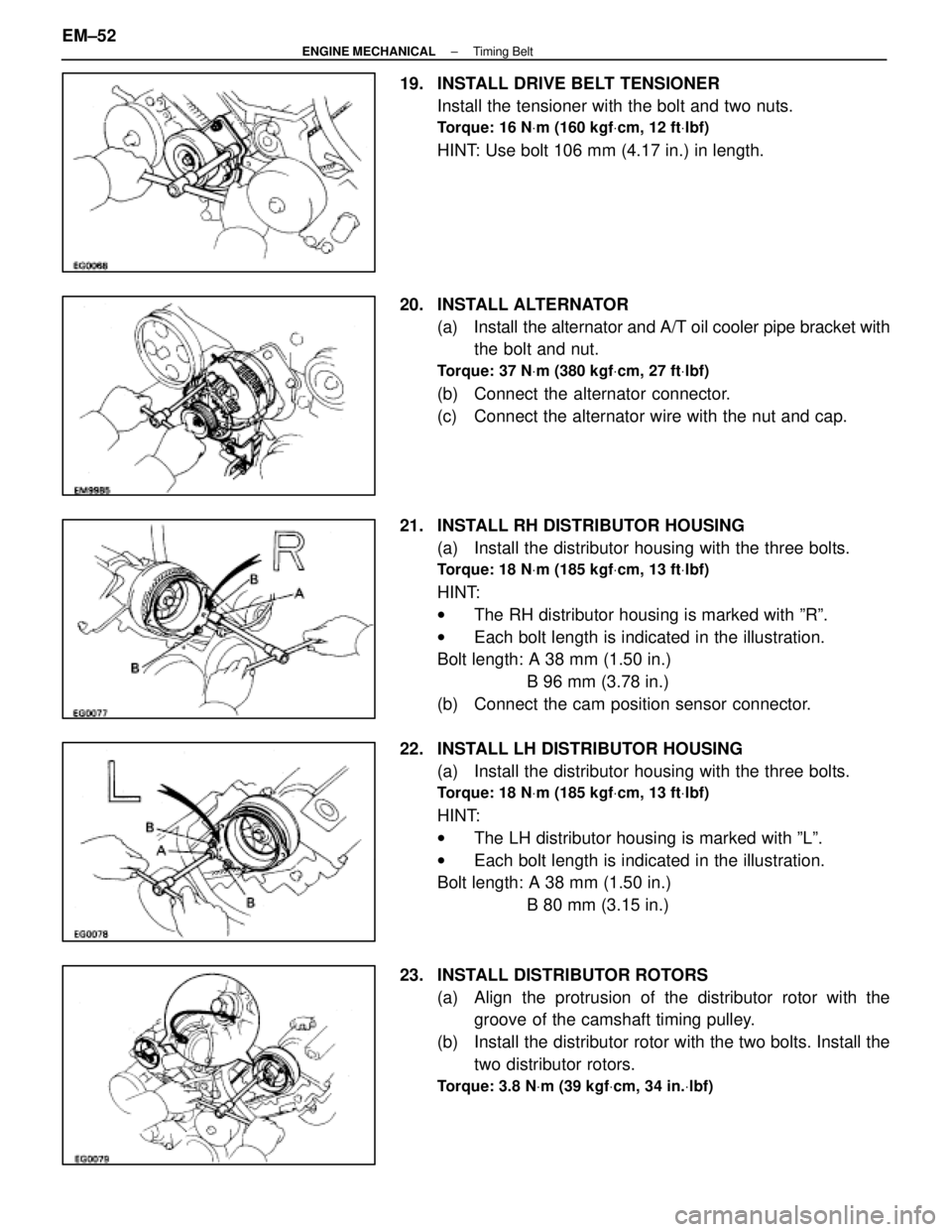
19. INSTALL DRIVE BELT TENSIONERInstall the tensioner with the bolt and two nuts.
Torque: 16 N Vm (160 kgf Vcm, 12 ft Vlbf)
HINT: Use bolt 106 mm (4.17 in.) in length.
20. INSTALL ALTERNATOR (a) Install the alternator and A/T oil cooler pipe bracket withthe bolt and nut.
Torque: 37 N Vm (380 kgf Vcm, 27 ft Vlbf)
(b) Connect the alternator connector.
(c) Connect the alternator wire with the nut and cap.
21. INSTALL RH DISTRIBUTOR HOUSING (a) Install the distributor housing with the three bolts.
Torque: 18 N Vm (185 kgf Vcm, 13 ft Vlbf)
HINT:
w The RH distributor housing is marked with ºRº.
w Each bolt length is indicated in the illustration.
Bolt length: A 38 mm (1.50 in.)
B 96 mm (3.78 in.)
(b) Connect the cam position sensor connector.
22. INSTALL LH DISTRIBUTOR HOUSING (a) Install the distributor housing with the three bolts.
Torque: 18 N Vm (185 kgf Vcm, 13 ft Vlbf)
HINT:
w The LH distributor housing is marked with ºLº.
w Each bolt length is indicated in the illustration.
Bolt length: A 38 mm (1.50 in.)
B 80 mm (3.15 in.)
23. INSTALL DISTRIBUTOR ROTORS (a) Align the protrusion of the distributor rotor with thegroove of the camshaft timing pulley.
(b) Install the distributor rotor with the two bolts. Install the two distributor rotors.
Torque: 3.8 N Vm (39 kgf Vcm, 34 in. Vlbf)
EM±52±
ENGINE MECHANICAL Timing Belt
WhereEverybodyKnowsYourName
Page 1726 of 4087
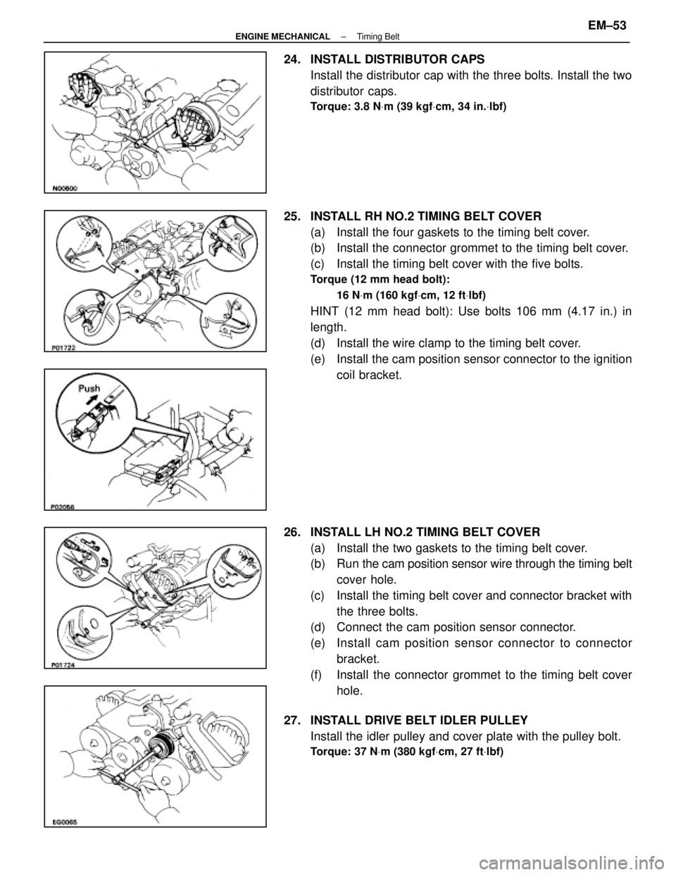
24. INSTALL DISTRIBUTOR CAPSInstall the distributor cap with the three bolts. Install the two
distributor caps.
Torque: 3.8 N Vm (39 kgf Vcm, 34 in. Vlbf)
25. INSTALL RH NO.2 TIMING BELT COVER
(a) Install the four gaskets to the timing belt cover.
(b) Install the connector grommet to the timing belt cover.
(c) Install the timing belt cover with the five bolts.
Torque (12 mm head bolt):
16 NVm (160 kgf Vcm, 12 ft Vlbf)
HINT (12 mm head bolt): Use bolts 106 mm (4.17 in.) in
length.
(d) Install the wire clamp to the timing belt cover.
(e) Install the cam position sensor connector to the ignition
coil bracket.
26. INSTALL LH NO.2 TIMING BELT COVER (a) Install the two gaskets to the timing belt cover.
(b) Run the cam po sition sensor wire through the timing belt
cover hole.
(c) Install the timing belt cover and connector bracket with the three bolts.
(d) Connect the cam position sensor connector.
(e) Install cam position sensor c onnector to connector
bracket.
(f) Install the connector grommet to the timing belt cover hole.
27. INSTALL DRIVE BELT IDLER PULLEY Install the idler pulley and cover plate with the pulley bolt.
Torque: 37 N Vm (380 kgf Vcm, 27 ft Vlbf)
±
ENGINE MECHANICAL Timing BeltEM±53
WhereEverybodyKnowsYourName
Page 1733 of 4087
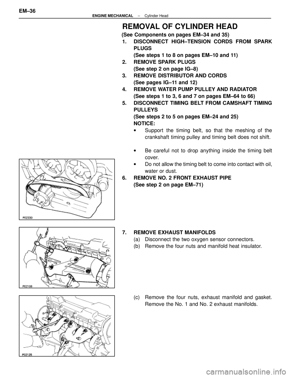
REMOVAL OF CYLINDER HEAD
(See Components on pages EM±34 and 35)1. DISCONNECT HIGH±TENSION CORDS FROM SPARK PLUGS
(See steps 1 to 8 on pages EM±10 and 11)
2. REMOVE SPARK PLUGS (See step 2 on page IG±8)
3. REMOVE DISTRIBUTOR AND CORDS
(See pages IG±11 and 12)
4. REMOVE WATER PUMP PULLEY AND RADIATOR (See steps 1 to 3, 6 and 7 on pages EM±64 to 66)
5. DISCONNECT TIMING BELT FROM CAMSHAFT TIMING PULLEYS
(See steps 2 to 5 on pages EM±24 and 25)
NOTICE:
wSupport the timing belt, so that the meshing of the
crankshaft timing pulley and timing belt does not shift.
w Be careful not to drop anything inside the timing belt
cover.
w Do not allow the timing belt to come into contact with oil,
water or dust.
6. REMOVE NO. 2 FRONT EXHAUST PIPE (See step 2 on page EM±71)
7. REMOVE EXHAUST MANIFOLDS (a) Disconnect the two oxygen sensor connectors.
(b) Remove the four nuts and manifold heat insulator.
(c) Remove the four nuts, exhaust manifold and gasket.Remove the No. 1 and No. 2 exhaust manifolds.
EM±36
±
ENGINE MECHANICAL Cylinder Head
WhereEverybodyKnowsYourName
Page 1735 of 4087
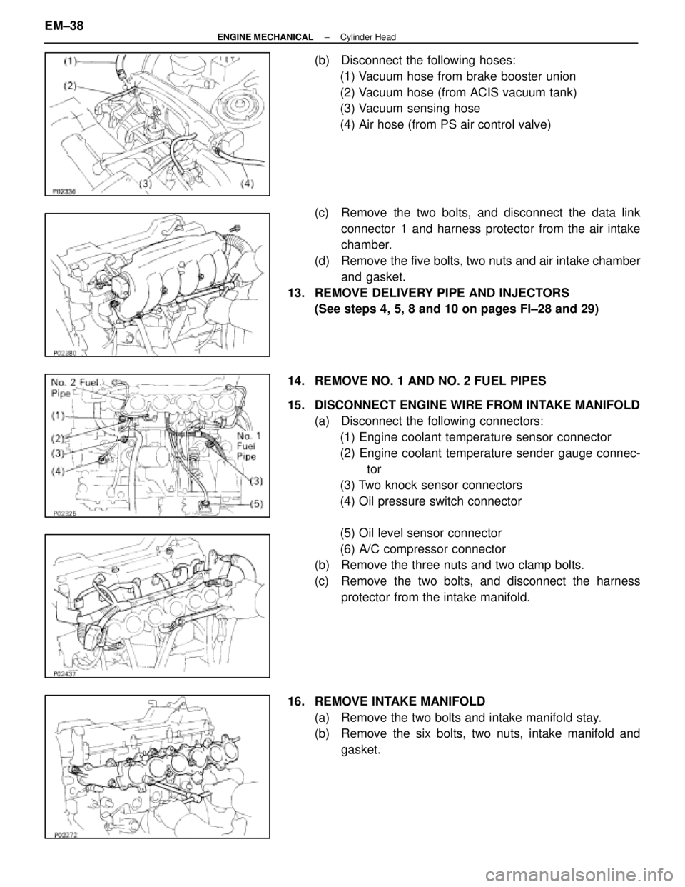
(b) Disconnect the following hoses:(1) Vacuum hose from brake booster union
(2) Vacuum hose (from ACIS vacuum tank)
(3) Vacuum sensing hose
(4) Air hose (from PS air control valve)
(c) Remove the two bolts, and disconnect the data link connector 1 and harness protector from the air intake
chamber.
(d) Remove the five bolts, two nuts and air intake chamber and gasket.
13. REMOVE DELIVERY PIPE AND INJECTORS (See steps 4, 5, 8 and 10 on pages FI±28 and 29)
14. REMOVE NO. 1 AND NO. 2 FUEL PIPES
15. DISCONNECT ENGINE WIRE FROM INTAKE MANIFOLD (a) Disconnect the following connectors:
(1) Engine coolant temperature sensor connector
(2) Engine coolant temperature sender gauge connec- tor
(3) Two knock sensor connectors
(4) Oil pressure switch connector
(5) Oil level sensor connector
(6) A/C compressor connector
(b) Remove the three nuts and two clamp bolts.
(c) Remove the two bolts, and disconnect the harness
protector from the intake manifold.
16. REMOVE INTAKE MANIFOLD (a) Remove the two bolts and intake manifold stay.
(b) Remove the six bolts, two nuts, intake manifold andgasket.
EM±38
±
ENGINE MECHANICAL Cylinder Head
WhereEverybodyKnowsYourName
Page 1739 of 4087
3. REMOVE ENGINE HANGERS
4. REMOVE ENGINE COOLANT TEMPERATURE SENSORAND SENDER GAUGE
5. REMOVE THROTTLE CABLE BRACKET AND GROUND STRAP
6. REMOVE EGR COOLER
INSPECTION, CLEANING AND REPAIR
OF CYLINDER HEAD COMPONENTS
1. CLEAN TOP SURFACES OF PISTONS AND CYLINDER BLOCK
(a) Turn the crankshaft, and bring each piston to top deadcenter (TDC). Using a gasket scraper, remove all the
carbon from the piston top surface.
(b) Using a gasket scraper, remove all the gasket material from the top surface of the cylinder block.
(c) Using compressed air, blow carbon and oil from the bolt
holes.
CAUTION: Protect your eyes when using high±com-
pressed air.
2. CLEAN CYLINDER HEAD
A. Remove gasket material Using a gasket scraper, remove all the gasket material from
the cylinder block surface.
NOTICE: Be careful not to scratch the cylinder block con-
tact surface.
EM±42
±
ENGINE MECHANICAL Cylinder Head
WhereEverybodyKnowsYourName
Page 1749 of 4087
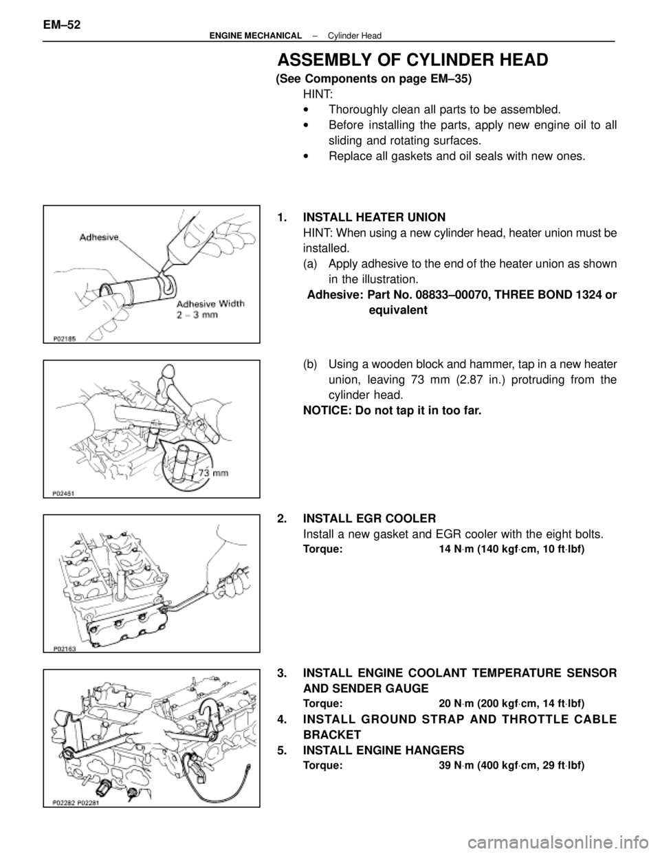
ASSEMBLY OF CYLINDER HEAD
(See Components on page EM±35)HINT:
wThoroughly clean all parts to be assembled.
w Before installing the parts, apply new engine oil to all
sliding and rotating surfaces.
w Replace all gaskets and oil seals with new ones.
1. INSTALL HEATER UNION HINT: When using a new cylinder head, heater union must be
installed.
(a) Apply adhesive to the end of the heater union as shownin the illustration.
Adhesive: Part No. 08833±00070, THREE BOND 1324 or equivalent
(b) Using a wooden block and hammer, tap in a new heater
union, leaving 73 mm (2.87 in.) protruding from the
cylinder head.
NOTICE: Do not tap it in too far.
2. INSTALL EGR COOLER Install a new gasket and EGR cooler with the eight bolts.
Torque: 14 N Vm (140 kgf Vcm, 10 ft Vlbf)
3. INSTALL ENGINE COOLANT TEMPERATURE SENSOR
AND SENDER GAUGE
Torque: 20 N Vm (200 kgf Vcm, 14 ft Vlbf)
4. INSTALL GROUND STRAP AND THROTTLE CABLE
BRACKET
5. INSTALL ENGINE HANGERS
Torque: 39 N Vm (400 kgf Vcm, 29 ft Vlbf)
EM±52±
ENGINE MECHANICAL Cylinder Head
WhereEverybodyKnowsYourName