Page 2063 of 4087
Injectors
ON±VEHICLE INSPECTION
1. INSPECT INJECTOR OPERATIONCheck operation sound from each injector.
(a) With the engine running or cranking, use a stethescopeto check that there is normal operating noise in
proportion to engine rpm.
(b) If you have no stethescope, you can check the injector transmission operation with your finger.
If no sound or an unusual sound is heard, check the wiring
connector, injector or injection signal from the ECU.
2. INSPECT INJECTOR RESISTANCE (a) Disconnect the injector connector.
(b) Using an ohmmeter, measure the resistance betweenthe terminals.
Resistance: 13.4±14.2 � at 20 5C (68 5F)
If the resistance is not as specified, replace the injector.
(c) Reconnect the injector connector.
FI±26
±
EFI SYSTEM Fuel System (Injectors)
WhereEverybodyKnowsYourName
Page 2072 of 4087
Fuel Pressure Pulsation Damper
COMPONENTS FOR REMOVAL AND
INSTALLATION
REMOVAL OF FUEL PRESSURE
PULSATION DAMPER
1. (A/T)REMOVE DIPSTICK GUIDE FOR TRANSMISSION
(a) Remove the mounting bolt.
(b) P u l l o u t t h e d i s t i c k g u i d e a n d d i p s t i c k f r o m t h etransmission.
(c) Remove the O±ring from the dipstick guide.
2. REMOVE STARTER (See page ST±5)
3. REMOVE FUEL PRESSURE PULSATION DAMPER (a) Remove the pulsation damper and upper gasket.
(b) Disc onnect the No. 1 fuel pipe from the fuel pipe
support, and remove the lower gasket.
±
EFI SYSTEM Fuel System (Fuel Pressure Pulsation Damper)FI±35
WhereEverybodyKnowsYourName
Page 2073 of 4087
INSTALLATION OF FUEL PRESSURE
PULSATION DAMPER
(See Components on page FI±35)
1. INSTALL FUEL PRESSURE PULSATION DAMPER (a) In sta ll two ne w ga ske ts, th e No . 1 fu e l pip e an dpulsation damper.
(b) Using SST, torque the pulsation damper.
SST 09612±24014 (09617±24011)
Torque: 41 N Vm (420 kgf Vcm, 30 ft Vlbf)
35 N Vm (350 kgf Vcm, 25 ft Vlbf) for SST
HINT: Use a torque wrench with a fulcrum length of 30 cm
(11.81 in.).
2. INSTALL STARTER (See page ST±5)
Torque: 39 N Vm (400 kgf Vcm, 29 ft Vlbf)
3. (A/T)
INSTALL DIPSTICK GUIDE FOR TRANSMISSION
(a) Install a new O±ring to the dipstick guide.
(b) Apply soapy water to the O±ring.
(c) Connect the dipstick guide end to the tube of the oil pan,
and install the dipstick guide with the bolt.
(d) Install the dipstick.
4. CHECK FOR FUEL LEAKS (See page FI±15)
FI±36
±
EFI SYSTEM Fuel System (Fuel Pressure Pulsation Damper)
WhereEverybodyKnowsYourName
Page 2117 of 4087
(c) Check the ignition timing.
Ignition timing: 8±125 BTDC @ idle
(Transmission in neutral range)
If the ignition timing is not as specified, check that following
conditions are normal: w Throttle valve fully closed
w Continuity between terminals IDL1 and E2 of the
throttle position sensor (See page FI±73)
w Valve timing (See page EM±51)
(e) Remove the SST from the check connector.
SST 09843±18020
17. DISCONNECT TACHOMETER AND TIMING LIGHT FROM ENGINE
18. INSTALL UPPER HIGH±TENSION CORD COVER (See step 10 on pages IG±18 and 19)
±
IGNITION SYSTEM DistributorIG±29
WhereEverybodyKnowsYourName
Page 2130 of 4087

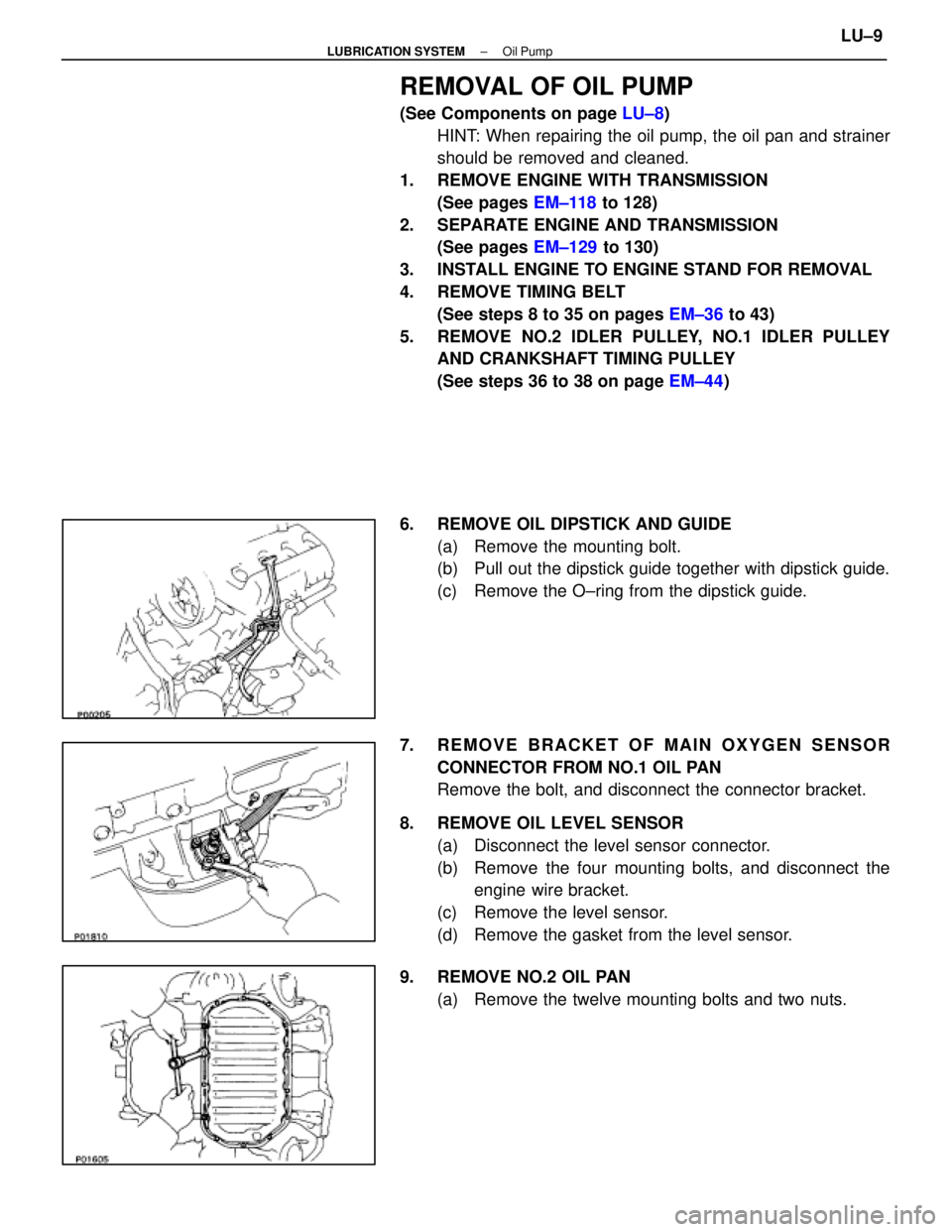
REMOVAL OF OIL PUMP
(See Components on page LU±8)
HINT: When repairing the oil pump, the oil pan and strainer
should be removed and cleaned.
1. REMOVE ENGINE WITH TRANSMISSION (See pages EM±118 to 128)
2. SEPARATE ENGINE AND TRANSMISSION (See pages EM±129 to 130)
3. INSTALL ENGINE TO ENGINE STAND FOR REMOVAL
4. REMOVE TIMING BELT (See steps 8 to 35 on pages EM±36 to 43)
5. REMOVE NO.2 IDLER PULLEY, NO.1 IDLER PULLEY AND CRANKSHAFT TIMING PULLEY
(See steps 36 to 38 on page EM±44)
6. REMOVE OIL DIPSTICK AND GUIDE (a) Remove the mounting bolt.
(b) Pull out the dipstick guide together with dipstick guide.
(c) Remove the O±ring from the dipstick guide.
7. REMOVE BRACKET OF MAIN OXYGEN SENSOR CONNECTOR FROM NO.1 OIL PAN
Remove the bolt, and disconnect the connector bracket.
8. REMOVE OIL LEVEL SENSOR (a) Disconnect the level sensor connector.
(b) Remove the four mounting bolts, and disconnect theengine wire bracket.
(c) Remove the level sensor.
(d) Remove the gasket from the level sensor.
9. REMOVE NO.2 OIL PAN (a) Remove the twelve mounting bolts and two nuts.
±
LUBRICATION SYSTEM Oil PumpLU±9
WhereEverybodyKnowsYourName
Page 2140 of 4087

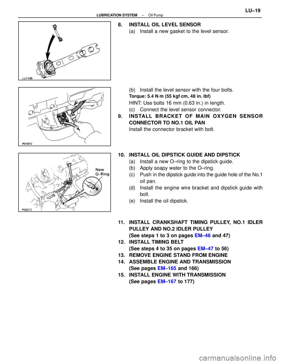
8. INSTALL OIL LEVEL SENSOR(a) Install a new gasket to the level sensor.
(b) Install the level sensor with the four bolts.
Torque: 5.4 N Vm (55 kgf Vcm, 48 in. Vlbf)
HINT: Use bolts 16 mm (0.63 in.) in length.
(c) Connect the level sensor connector.
9. INSTALL BRACKET OF MAIN OXYGEN SENSOR CONNECTOR TO NO.1 OIL PAN
Install the connector bracket with bolt.
10. INSTALL OIL DIPSTICK GUIDE AND DIPSTICK (a) Install a new O±ring to the dipstick guide.
(b) Apply soapy water to the O±ring.
(c) Push in the dipstick guide into the guide hole of the No.1
oil pan.
(d) Install the engine wire bracket and dipstick guide with bolt.
(e) Install the oil dipstick.
11. INSTALL CRANKSHAFT TIMING PULLEY, NO.1 IDLER PULLEY AND NO.2 IDLER PULLEY
(See steps 1 to 3 on pages EM±46 and 47)
12. INSTALL TIMING BELT
(See steps 4 to 35 on pages EM±47 to 56)
13. REMOVE ENGINE STAND FROM ENGINE
14. ASSEMBLE ENGINE AND TRANSMISSION (See pages EM±165 and 166)
15. INSTALL ENGINE WITH TRANSMISSION (See pages EM±167 to 177)
±
LUBRICATION SYSTEM Oil PumpLU±19
WhereEverybodyKnowsYourName
Page 2142 of 4087

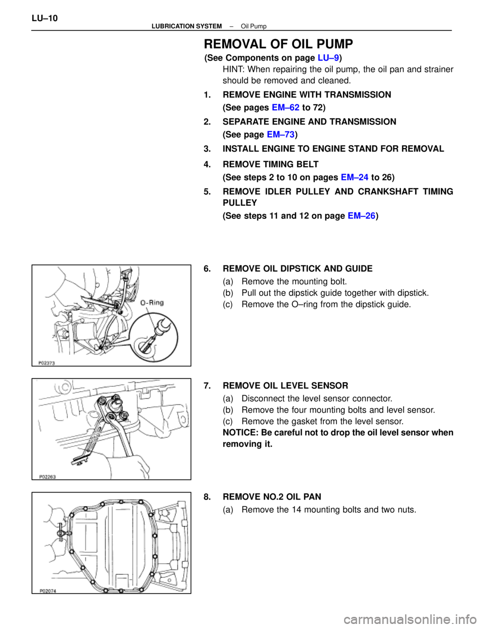
REMOVAL OF OIL PUMP
(See Components on page LU±9)
HINT: When repairing the oil pump, the oil pan and strainer
should be removed and cleaned.
1. REMOVE ENGINE WITH TRANSMISSION (See pages EM±62 to 72)
2. SEPARATE ENGINE AND TRANSMISSION (See page EM±73)
3. INSTALL ENGINE TO ENGINE STAND FOR REMOVAL
4. REMOVE TIMING BELT (See steps 2 to 10 on pages EM±24 to 26)
5. REMOVE IDLER PULLEY AND CRANKSHAFT TIMING PULLEY
(See steps 11 and 12 on page EM±26)
6. REMOVE OIL DIPSTICK AND GUIDE (a) Remove the mounting bolt.
(b) Pull out the dipstick guide together with dipstick.
(c) Remove the O±ring from the dipstick guide.
7. REMOVE OIL LEVEL SENSOR (a) Disconnect the level sensor connector.
(b) Remove the four mounting bolts and level sensor.
(c) Remove the gasket from the level sensor.
NOTICE: Be careful not to drop the oil level sensor when
removing it.
8. REMOVE NO.2 OIL PAN (a) Remove the 14 mounting bolts and two nuts.
LU±10
±
LUBRICATION SYSTEM Oil Pump
WhereEverybodyKnowsYourName
Page 2150 of 4087
6. INSTALL OIL LEVEL SENSOR(a) Install a new gasket to the level sensor.
(b) Install the level sensor with the four bolts.
Torque: 5.4 N Vm (55 kgf Vcm, 48 in. Vlbf)
(c) Connect the level sensor connector.
7. INSTALL OIL DIPSTICK GUIDE AND DIPSTICK (a) Install a new O±ring on the dipstick guide.
(b) Apply soapy water on the O±ring.
(c) Push in the dipstick guide into the guide hole of the No.1
oil pan.
(d) Install the guide with the mounting bolt.
8. INSTALL CRANKSHAFT TIMING PULLEY AND IDLER PULLEY
(See steps 1 and 2 on page EM±29)
9. INSTALL TIMING BELT (See steps 3 to 14 on pages EM±29 to 33)
10. REMOVE ENGINE STAND FROM ENGINE
11. ASSEMBLE ENGINE AND TRANSMISSION (See page EM±103)
12. INSTALL ENGINE WITH TRANSMISSION (See pages EM±104 to 112)
LU±18
±
LUBRICATION SYSTEM Oil Pump
WhereEverybodyKnowsYourName