Page 1634 of 4087
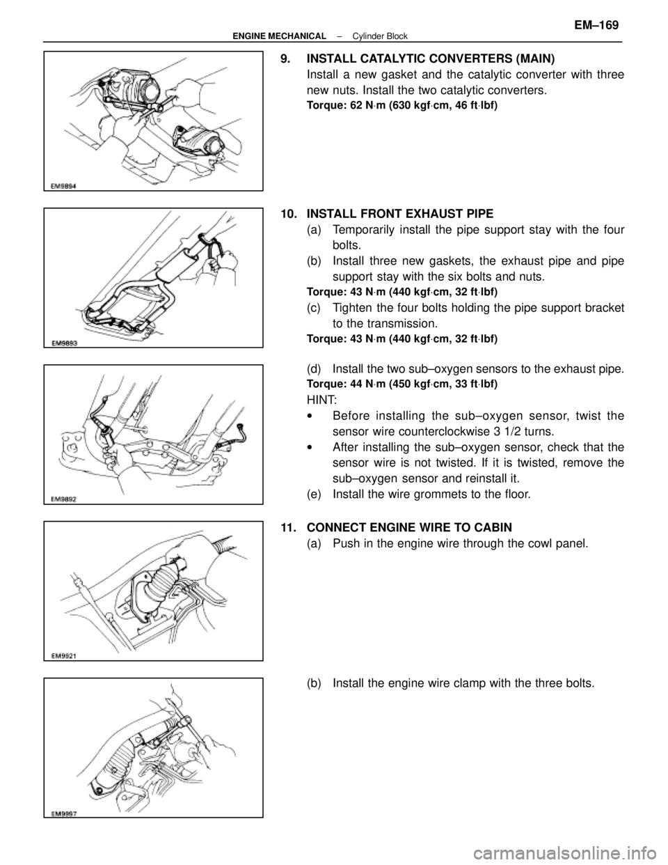
9. INSTALL CATALYTIC CONVERTERS (MAIN)Install a new gasket and the catalytic converter with three
new nuts. Install the two catalytic converters.
Torque: 62 N Vm (630 kgf Vcm, 46 ft Vlbf)
10. INSTALL FRONT EXHAUST PIPE
(a) Temporarily install the pipe support stay with the fourbolts.
(b) Install three new gaskets, the exhaust pipe and pipe support stay with the six bolts and nuts.
Torque: 43 N Vm (440 kgf Vcm, 32 ft Vlbf)
(c) Tighten the four bolts holding the pipe support bracket
to the transmission.
Torque: 43 N Vm (440 kgf Vcm, 32 ft Vlbf)
(d) Install the two sub±oxygen sensors to the exhaust pipe.
Torque: 44 N Vm (450 kgf Vcm, 33 ft Vlbf)
HINT:
w Before installing the s ub±oxygen sensor, twist the
sensor wire counterclockwise 3 1/2 turns.
w After installing the sub±oxygen sensor, check that the
sensor wire is not twisted. If it is twisted, remove the
sub±oxygen sensor and reinstall it.
(e) Install the wire grommets to the floor.
11. CONNECT ENGINE WIRE TO CABIN (a) Push in the engine wire through the cowl panel.
(b) Install the engine wire clamp with the three bolts.
±
ENGINE MECHANICAL Cylinder BlockEM±169
WhereEverybodyKnowsYourName
Page 1642 of 4087
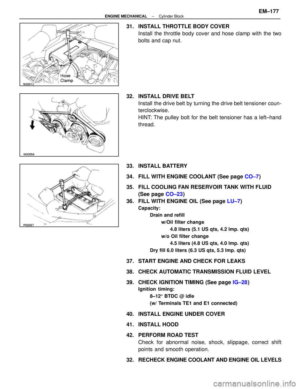
31. INSTALL THROTTLE BODY COVERInstall the throttle body cover and hose clamp with the two
bolts and cap nut.
32. INSTALL DRIVE BELT Install the drive belt by turning the drive belt tensioner coun-
terclockwise.
HINT: The pulley bolt for the belt tensioner has a left±hand
thread.
33. INSTALL BATTERY
34. FILL WITH ENGINE COOLANT (See page CO±7)
35. FILL COOLING FAN RESERVOIR TANK WITH FLUID (See page CO±23)
36. FILL WITH ENGINE OIL (See page LU±7)
Capacity:
Drain and refill
w/Oil filter change4.8 liters (5.1 US qts, 4.2 lmp. qts)
w/o Oil filter change 4.5 liters (4.8 US qts, 4.0 lmp. qts)
Dry fill 6.0 liters (6.3 US qts, 5.3 lmp. qts)
37. START ENGINE AND CHECK FOR LEAKS
38. CHECK AUTOMATIC TRANSMISSION FLUID LEVEL
39. CHECK IGNITION TIMING (See page IG±28)
Ignition timing:
8±125 BTDC @ idle
(w/ Terminals TE1 and E1 connected)
40. INSTALL ENGINE UNDER COVER
41. INSTALL HOOD
42. PERFORM ROAD TEST Check for abnormal noise, shock, slippage, correct shift
points and smooth operation.
32. RECHECK ENGINE COOLANT AND ENGINE OIL LEVELS
±
ENGINE MECHANICAL Cylinder BlockEM±177
WhereEverybodyKnowsYourName
Page 1649 of 4087
SST (SPECIAL SERVICE TOOLS) (Cont'd)
(09248±05021)(Valve Lifter
Stopper)
09316±60010Transmission &
Transfer Bearing
Replacer
Crankshaft timing pulley
09278±54012Drive Shaft Holding
Tool
M/T (W58) only
09325±20010Transmission Oil
Plug
(09316±00010)(Replacer Pipe)
Crankshaft front oil seal and camshaft oil seal
(09316±00050)(Replacer ºDº)
Camshaft oil seal
A/T (A340E) only
09325±40010Transmission Oil
Plug
Crankshaft pulley
09330±00021Companion Flange
Holding Tool
09608±30022Front Hub Bearing
Replacer Set
Knock sensor and oil pressure switch
09816±30010Oil Pressure
Switch Socket
(09608±05010)(Handle)
Crankshaft rear oiil seal
RECOMMENDED TOOLS
Cylinder head bolt
09043±5010010 mm Bi±Hexagon
wrench
A/C compressor mounting through bolt
09044±00020Torx Socket
E10
±
ENGINE MECHANICAL PreparationEM±5
WhereEverybodyKnowsYourName
Page 1687 of 4087
IDLE AND/OR 2,500 RPM CO/HC
CHECK
HINT: This check is used only to determine whether or not the
idle CO/HC complies with regulations.
1. INITIAL CONDITIONS (a) Engine at normal operating temperature.
(b) Air cleaner installed.
(c) All pipes and hoses of air induction system connected.
(d) All accessories switched OFF.
(e) All vacuum lines properly connected.
HINT: All vacuum hoses for EGR systems, etc. should be
properly connected.
(f) SFI system wiring connectors fully plugged.
(g) Transmission in neutral.
(h) Tachometer and CO/HC analyzer calibrated and athand.
2. START ENGINE
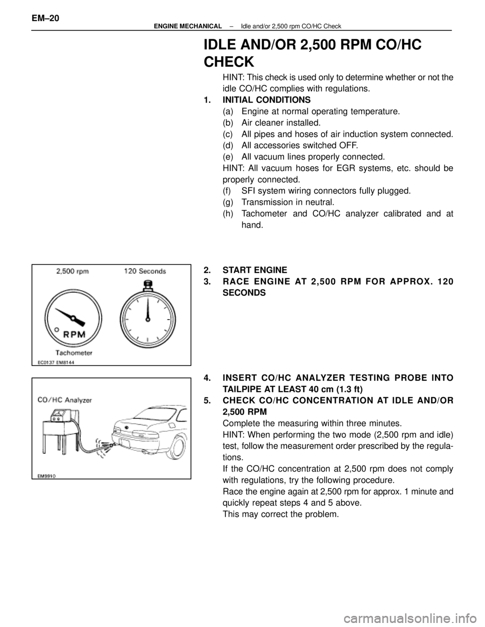
3. RACE ENGINE AT 2,500 RPM FOR APPROX. 120 SECONDS
4. INSERT CO/HC ANALYZER TESTING PROBE INTO TAILPIPE AT LEAST 40 cm (1.3 ft)
5. CHECK CO/HC CONCENTRATION AT IDLE AND/OR
2,500 RPM
Complete the measuring within three minutes.
HINT: When performing the two mode (2,500 rpm and idle)
test, follow the measurement order prescribed by the regula-
tions.
If the CO/HC concentration at 2,500 rpm does not comply
with regulations, try the following procedure.
Race the engine again at 2,500 rpm for approx. 1 minute and
quickly repeat steps 4 and 5 above.
This may correct the problem.
EM±20
±
ENGINE MECHANICAL Idle and/or 2,500 rpm CO/HC Check
WhereEverybodyKnowsYourName
Page 1700 of 4087
14. INSTALL NO. 2 AND NO. 3 TIMING BELT COVERS(a) Install the gasket on the timing belt cover.
(b) Using a 5 mm hexagon wrench, install the belt coverswith the nine bolts.
(c) Install the oil filler cap.
15. INSTALL RADIATOR AND WATER PUMP PULLEY (See steps 15, 16, 19 and 24 on pages EM±110 to 112)
16. FILL ENGINE WITH COOLANT (See page CO±5)
Capacity (w/ Heater):
M/T 8.5 liters (9.0 US qts, 7.5 Imp. qts)
A/T 8.4 liters (8.9 US qts, 7.4 Imp. qts)
17. (A/T)CHECK AUTOMATIC TRANSMISSION FLUID LEVEL
(See page MA±11)
NOTICE: Do not overfill.
18. START ENGINE AND CHECK FOR LEAKS
19. CHECK IGNITION TIMING (See page IG±14)
Ignition timing:
105 BTDC @ idle
(w/ Terminals TE1 and E1 connected)
20. PERFORM ROAD TEST Check for abnormal noise, shock, slippage, correct shift
points and smooth operation.
21. RECHECK ENGINE COOLANT LEVEL
±
ENGINE MECHANICAL Timing BeltEM±33
WhereEverybodyKnowsYourName
Page 1701 of 4087
IDLE AND/OR 2,500 RPM HC/CO
CONCENTRATION CHECK METHOD
HINT: This check is used only to determine whether or not the
idle HC/CO complies with regulations.
1. INTIAL CONDITIONS (a) Engine at normal operating temperature.
(b) Air cleaner installed.
(c) All pipes and hoses of air induction system connected.
(d) All accessories switched OFF.
(e) All vacuum lines properly connected.
HINT: All vacuum hoses for EGR systems, etc. should be
properly connected.
(f) EFI system wiring connectors fully plugged.
(g) Transmission in neutral range.
(h) Tachometer and HC/CO meter calibrated at hand.
2. START ENGINE
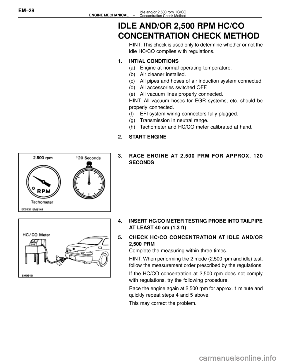
3. RACE ENGINE AT 2,500 PRM FOR APPROX. 120 SECONDS
4. INSERT HC/CO METER TESTING PROBE INTO TAILPIPE AT LEAST 40 cm (1.3 ft)
5. CHECK HC/CO CONCENTRATION AT IDLE AND/OR 2,500 PRM
Complete the measuring within three times.
HINT: When performing the 2 mode (2,500 rpm and idle) test,
follow the measurement order prescribed by the regulations.
If the HC/CO concentration at 2,500 rpm does not comply
with regulations, try the following procedure.
Race the engine again at 2,500 rpm for approx. 1 minute and
quickly repeat steps 4 and 5 above.
This may correct the problem.
EM±28
±
ENGINE MECHANICAL Idle and/or 2,500 rpm HC/CO
Concentration Check Method
WhereEverybodyKnowsYourName
Page 1734 of 4087
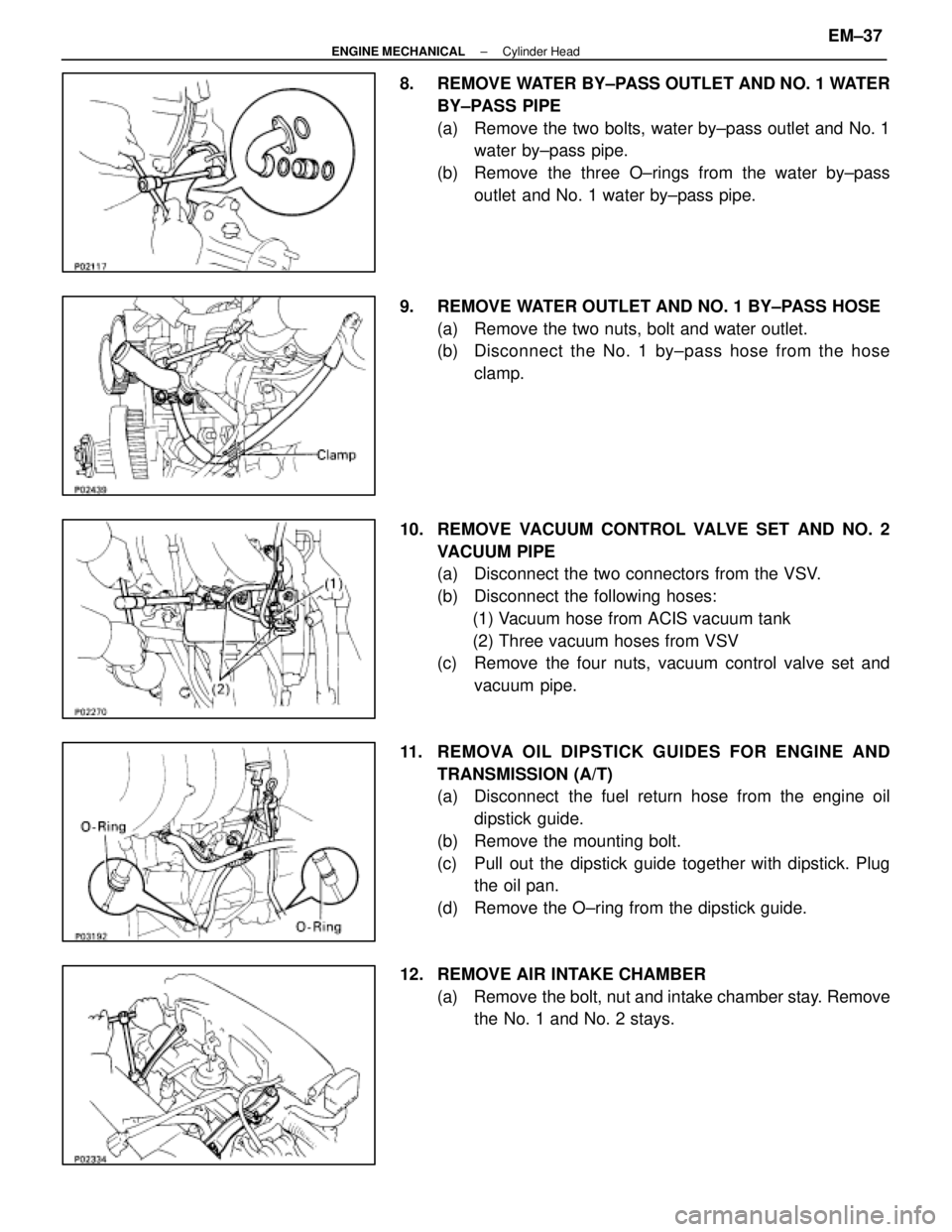
8. REMOVE WATER BY±PASS OUTLET AND NO. 1 WATERBY±PASS PIPE
(a) Remove the two bolts, water by±pass outlet and No. 1water by±pass pipe.
(b) Remove the three O±rings from the water by±pass outlet and No. 1 water by±pass pipe.
9. REMOVE WATER OUTLET AND NO. 1 BY±PASS HOSE (a) Remove the two nuts, bolt and water outlet.
(b) Disc onnect the No. 1 by±pass hose from the hose
clamp.
10. REMOVE VACUUM CONTROL VALVE SET AND NO. 2 VACUUM PIPE
(a) Disconnect the two connectors from the VSV.
(b) Disconnect the following hoses:(1) Vacuum hose from ACIS vacuum tank
(2) Three vacuum hoses from VSV
(c) Remove the four nuts, vacuum control valve set and
vacuum pipe.
11. REMOVA OIL DIPSTICK GUIDES FOR ENGINE AND TRANSMISSION (A/T)
(a) Disconnect the fuel return hose from the engine oildipstick guide.
(b) Remove the mounting bolt.
(c) Pull out the dipstick guide together with dipstick. Plug the oil pan.
(d) Remove the O±ring from the dipstick guide.
12. REMOVE AIR INTAKE CHAMBER (a) Remove the bolt, nut and intake chamber stay. Removethe No. 1 and No. 2 stays.
±
ENGINE MECHANICAL Cylinder HeadEM±37
WhereEverybodyKnowsYourName
Page 1757 of 4087
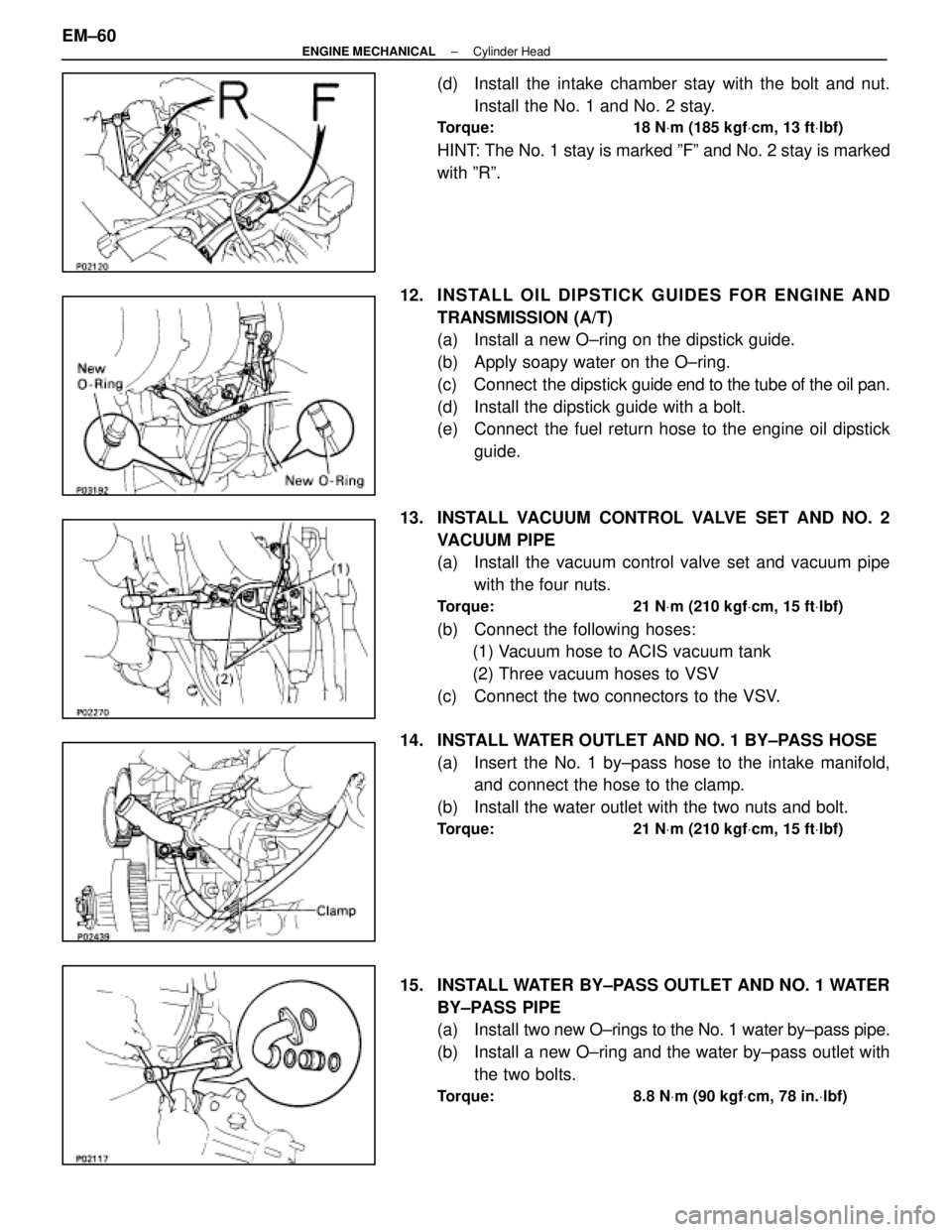
(d) Install the intake chamber stay with the bolt and nut.Install the No. 1 and No. 2 stay.
Torque: 18 N Vm (185 kgf Vcm, 13 ft Vlbf)
HINT: The No. 1 stay is marked ºFº and No. 2 stay is marked
with ºRº.
12. INS TALL OIL DIP S TICK GUIDE S FO R ENG INE AND TRANSMISSION (A/T)
(a) Install a new O±ring on the dipstick guide.
(b) Apply soapy water on the O±ring.
(c) Connect the dipstick guide end to the tube of the oil pan.
(d) Install the dipstick guide with a bolt.
(e) Connect the fuel return hose to the engine oil dipstick guide.
13. INSTALL VACUUM CONTROL VALVE SET AND NO. 2 VACUUM PIPE
(a) Install the vacuum control valve set and vacuum pipewith the four nuts.
Torque: 21 N Vm (210 kgf Vcm, 15 ft Vlbf)
(b) Connect the following hoses:
(1) Vacuum hose to ACIS vacuum tank
(2) Three vacuum hoses to VSV
(c) Connect the two connectors to the VSV.
14. INSTALL WATER OUTLET AND NO. 1 BY±PASS HOSE (a) Insert the No. 1 by±pass hose to the intake manifold,and connect the hose to the clamp.
(b) Install the water outlet with the two nuts and bolt.
Torque: 21 N Vm (210 kgf Vcm, 15 ft Vlbf)
15. INSTALL WATER BY±PASS OUTLET AND NO. 1 WATER
BY±PASS PIPE
(a) Install two new O±rings to the No. 1 water by±pass pipe.
(b) Install a new O±ring and the water by±pass outlet with the two bolts.
Torque: 8.8 N Vm (90 kgf Vcm, 78 in. Vlbf)
EM±60±
ENGINE MECHANICAL Cylinder Head
WhereEverybodyKnowsYourName