Page 1867 of 4087
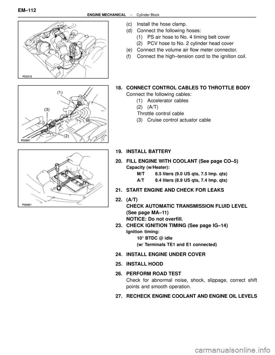
(c) Install the hose clamp.
(d) Connect the following hoses:(1) PS air hose to No. 4 timing belt cover
(2) PCV hose to No. 2 cylinder head cover
(e) Connect the volume air flow meter connector.
(f) Connect the high±tension cord to the ignition coil.
18. CONNECT CONTROL CABLES TO THROTTLE BODY Connect the following cables:(1) Accelerator cables
(2) (A/T)
Throttle control cable
(3) Cruise control actuator cable
19. INSTALL BATTERY
20. FILL ENGINE WITH COOLANT (See page CO±5)
Capacity (w/Heater): M/T 8.5 liters (9.0 US qts, 7.5 lmp. qts)
A/T 8.4 liters (8.9 US qts, 7.4 lmp. qts)
21. START ENGINE AND CHECK FOR LEAKS
22. (A/T)CHECK AUTOMATIC TRANSMISSION FLUID LEVEL
(See page MA±11)
NOTICE: Do not overfill.
23. CHECK IGNITION TIMING (See page IG±14)
Ignition timing:
105 BTDC @ idle
(w/ Terminals TE1 and E1 connected)
24. INSTALL ENGINE UNDER COVER
25. INSTALL HOOD
26. PERFORM ROAD TEST Check for abnormal noise, shock, slippage, correct shift
points and smooth operation.
27. RECHECK ENGINE COOLANT AND ENGINE OIL LEVELS
EM±112
±
ENGINE MECHANICAL Cylinder Block
WhereEverybodyKnowsYourName
Page 1872 of 4087
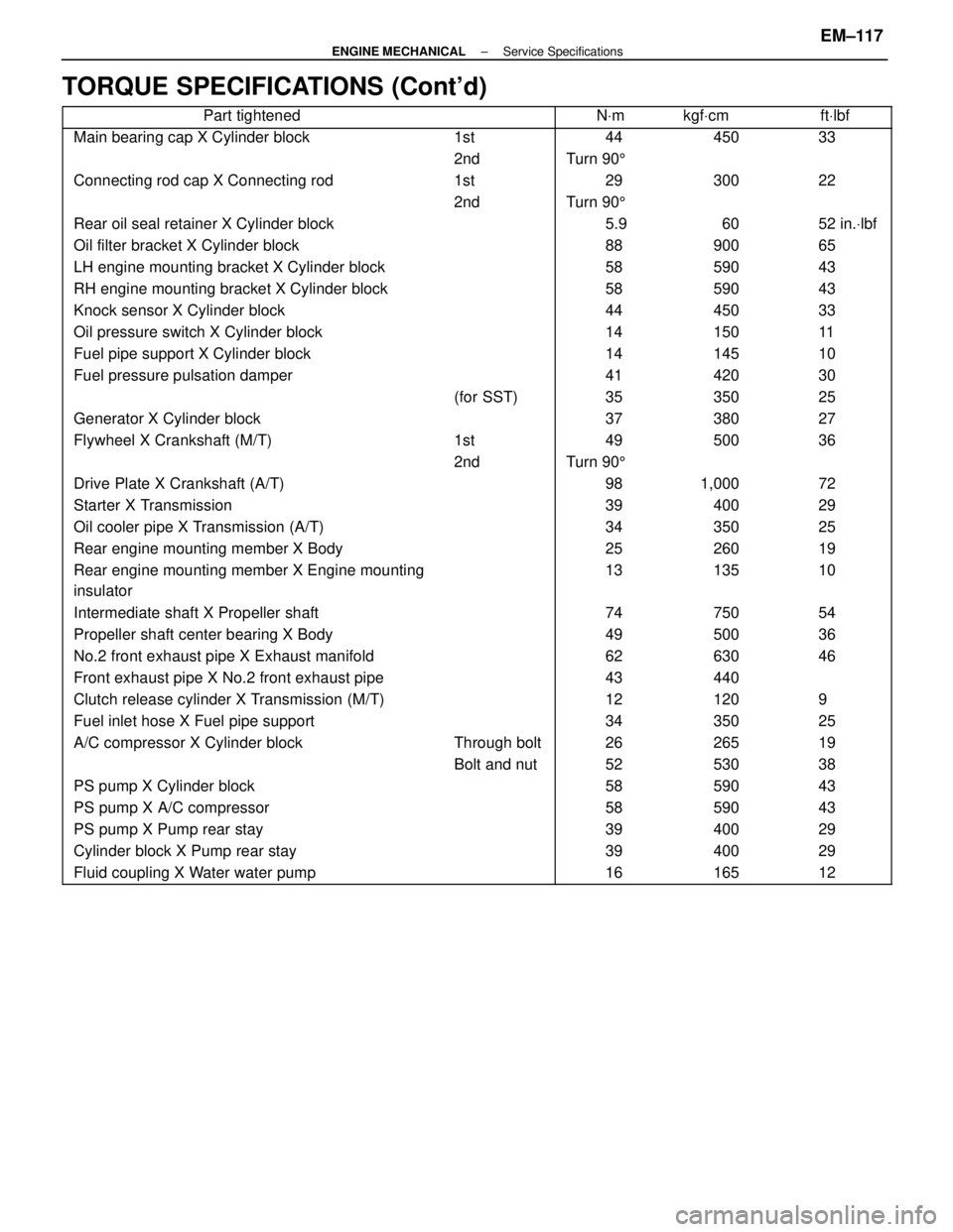
TORQUE SPECIFICATIONS (Cont'd)
����������������� �����������������Part tightened������ ����������� �����NVm������ ������kgf Vcm������ ������ft Vlbf
����������������� �����������������Main bearing cap X Cylinder block������ ������1st����� �����44������ ������450������ ������33
����������������� ����������������������� ������2nd����� �����Turn 90 5������ ������������ ������
����������������� �����������������Connecting rod cap X Connecting rod������ ������1st����� �����29������ ������300������ ������22
�����������������������2nd�����Turn 905����������������������������� �����������������Rear oil seal retainer X Cylinder block������ ����������� �����5.9������ ������60������ ������52 in.Vlbf����������������� �����������������Oil filter bracket X Cylinder block������ ����������� �����88������ ������900������ ������65����������������� �����������������LH engine mounting bracket X Cylinder block������ ����������� �����58������ ������590������ ������43����������������� �����������������RH engine mounting bracket X Cylinder block������ ����������� �����58������ ������590������ ������43
����������������� �����������������Knock sensor X Cylinder block������ ����������� �����44������ ������450������ ������33
����������������� �����������������Oil pressure switch X Cylinder block������ ����������� �����14������ ������150������ ������11
����������������� �����������������Fuel pipe support X Cylinder block������ ����������� �����14������ ������145������ ������10
����������������� �����������������Fuel pressure pulsation damper������ ����������� �����41������ ������420������ ������30
����������������� ����������������������� ������(for SST)����� �����35������ ������350������ ������25
����������������� �����������������Generator X Cylinder block������ ����������� �����37������ ������380������ ������27
�����������������Flywheel X Crankshaft (M/T)������1st�����49������500������36����������������� ����������������������� ������2nd����� �����Turn 90 5������ ������������ ������
����������������� �����������������Drive Plate X Crankshaft (A/T)������ ����������� �����98������ ������1,000������ ������72����������������� �����������������Starter X Transmission������ ����������� �����39������ ������400������ ������29����������������� �����������������Oil cooler pipe X Transmission (A/T)������ ����������� �����34������ ������350������ ������25
����������������� �����������������Rear engine mounting member X Body������ ����������� �����25������ ������260������ ������19
����������������� �
����������������
�����������������
Rear engine mounting member X Engine mounting
insulator������ �
�����
������
����� �
����
�����
13������ �
�����
������
135������ �
�����
������
10
����������������� �����������������Intermediate shaft X Propeller shaft������ ����������� �����74������ ������750������ ������54
����������������� �����������������Propeller shaft center bearing X Body������ ����������� �����49������ ������500������ ������36
�����������������No.2 front exhaust pipe X Exhaust manifold�����������62������630������46����������������� �����������������Front exhaust pipe X No.2 front exhaust pipe������ ����������� �����43������ ������440������ ������
����������������� �����������������Clutch release cylinder X Transmission (M/T)������ ����������� �����12������ ������120������ ������9����������������� �����������������Fuel inlet hose X Fuel pipe support������ ����������� �����34������ ������350������ ������25����������������� �����������������A/C compressor X Cylinder block������ ������Through bolt����� �����26������ ������265������ ������19
����������������� ����������������������� ������Bolt and nut����� �����52������ ������530������ ������38
����������������� �����������������PS pump X Cylinder block������ ����������� �����58������ ������590������ ������43
����������������� �����������������PS pump X A/C compressor������ ����������� �����58������ ������590������ ������43
����������������� �����������������PS pump X Pump rear stay������ ����������� �����39������ ������400������ ������29
����������������� �����������������Cylinder block X Pump rear stay������ ����������� �����39������ ������400������ ������29
����������������� �����������������Fluid coupling X Water water pump������ ����������� �����16������ ������165������ ������12
±
ENGINE MECHANICAL Service SpecificationsEM±117
WhereEverybodyKnowsYourName
Page 1889 of 4087
COMPONENTS
REMOVAL OF ACOUSTIC CONTROL
INDUCTION SYSTEM (ACIS)
1. DISCONNECT CABLE FROM NEGATIVE TERMINAL OFBATTERY
CAUTION: Turn the ignition switch to ºLOCKº. Discon-
nect the cable from the negative (±) terminal of the bat-
tery. Wait at least 20 seconds before proceeding with
work.
2. (A/T) REMOVE DIPSTICK GUIDE FOR TRANSMISSION
(a) Remove the mounting bolt.
(b) P u ll ou t th e dip stick gu id e an d dip stick fro m th etransmission.
(c) Remove the O±ring from the dipstic guide.
±
EFI SYSTEMFI±57
Air Induction System (Acoustic Control Induction System (ACIS)
WhereEverybodyKnowsYourName
Page 1894 of 4087
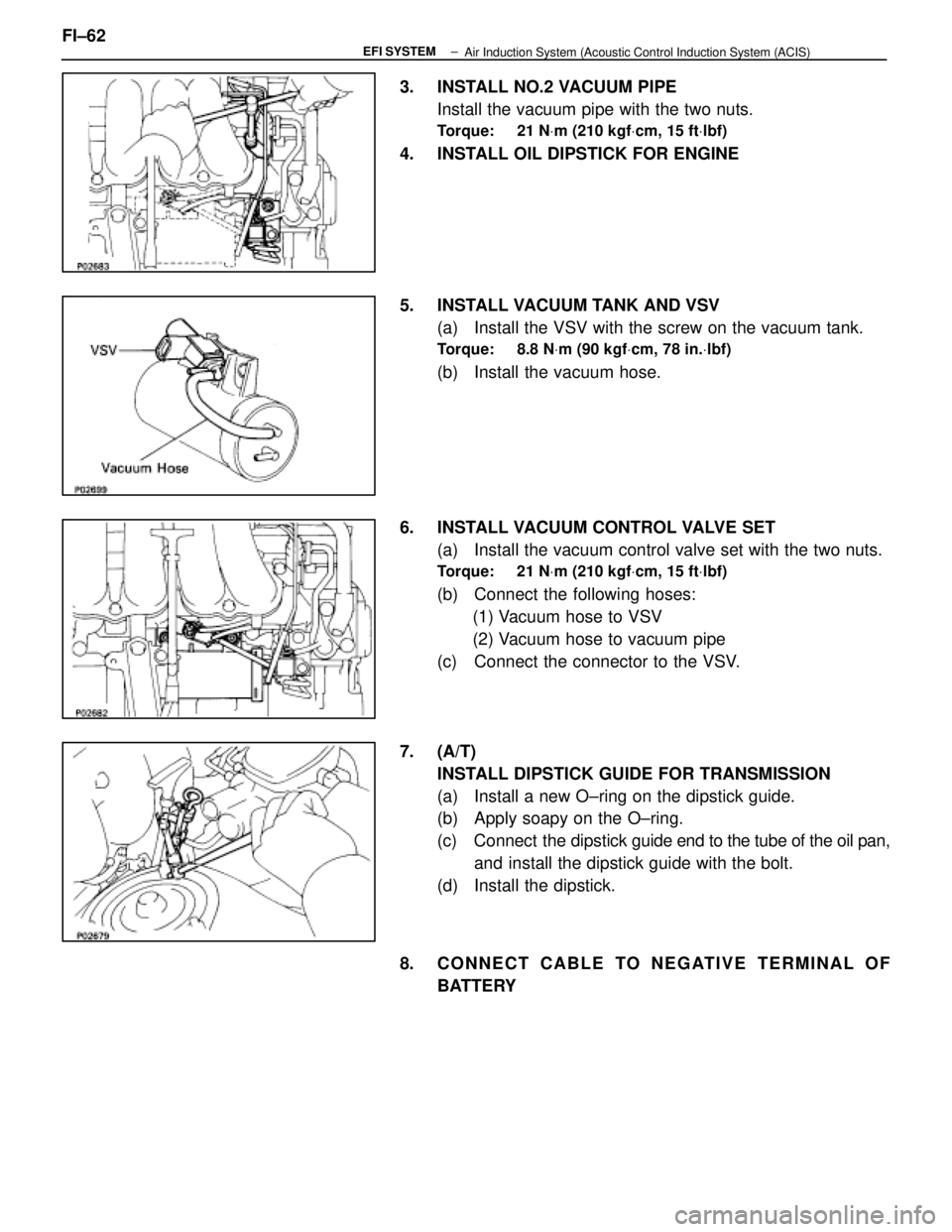
3. INSTALL NO.2 VACUUM PIPEInstall the vacuum pipe with the two nuts.
Torque: 21 N Vm (210 kgf Vcm, 15 ft Vlbf)
4. INSTALL OIL DIPSTICK FOR ENGINE
5. INSTALL VACUUM TANK AND VSV
(a) Install the VSV with the screw on the vacuum tank.
Torque: 8.8 N Vm (90 kgf Vcm, 78 in. Vlbf)
(b) Install the vacuum hose.
6. INSTALL VACUUM CONTROL VALVE SET (a) Install the vacuum control valve set with the two nuts.
Torque: 21 N Vm (210 kgf Vcm, 15 ft Vlbf)
(b) Connect the following hoses:
(1) Vacuum hose to VSV
(2) Vacuum hose to vacuum pipe
(c) Connect the connector to the VSV.
7. (A/T) INSTALL DIPSTICK GUIDE FOR TRANSMISSION
(a) Install a new O±ring on the dipstick guide.
(b) Apply soapy on the O±ring.
(c) Connect the dipstick guide end to the tube of the oil pan,
and install the dipstick guide with the bolt.
(d) Install the dipstick.
8. CONNECT CABLE TO NEGATIVE TERMINAL OF BATTERY
FI±62
±
EFI SYSTEM
Air Induction System (Acoustic Control Induction System (ACIS)
WhereEverybodyKnowsYourName
Page 1927 of 4087
INSPECTION OF SUB±OXYGEN SENSOR
1. INSPECT SUB±OXYGEN SENSOR(a) Cancel diagnostic code. (See TR section)
(b) A llo w th e en g in e to wa rm up to no rma l op e ra tin gtemperature.
(c) Drive for 5 minutes or more between 80km/h (50 mph) and 100 km/h (62 mph) in ºDº range.
(d) Following the conditions in step (c), press fully on the
accelerator pedal for 2 seconds or more.
HINT: Do not exceed 100 km/h (62 mph), or diagnostic code
will be cancelled.
(e) Stop the vehicle, and turn the ignition switch to OFF.
(f) Carry out steps (b), (c) and (d) again to test acceleration.
If code No. 27 reappears again, check the sub±oxygen sen-
sor circuit. If the circuit is normal, replace the sub±oxygen
sensor.
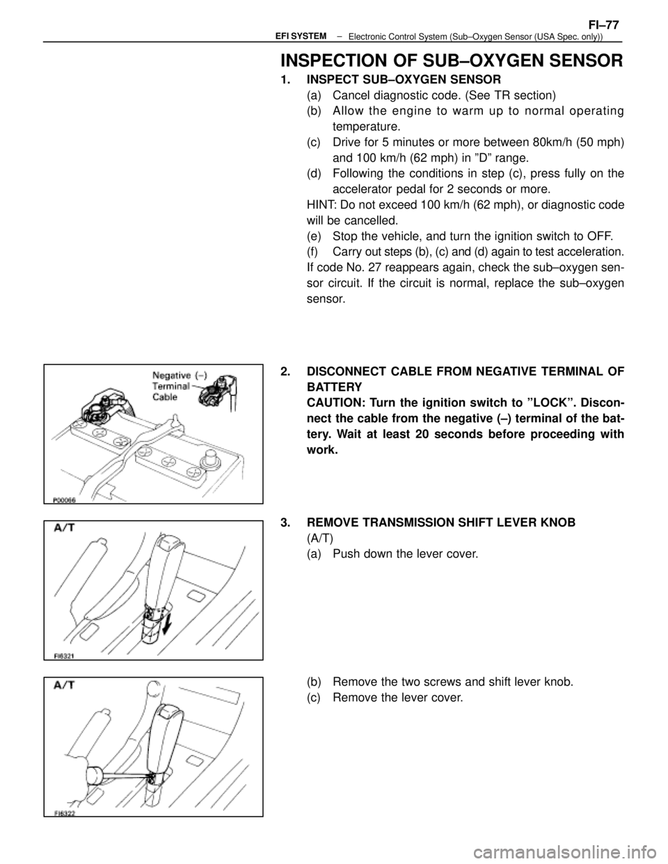
2. DISCONNECT CABLE FROM NEGATIVE TERMINAL OF BATTERY
CAUTION: Turn the ignition switch to ºLOCKº. Discon-
nect the cable from the negative (±) terminal of the bat-
tery. Wait at least 20 seconds before proceeding with
work.
3. REMOVE TRANSMISSION SHIFT LEVER KNOB (A/T)
(a) Push down the lever cover.
(b) Remove the two screws and shift lever knob.
(c) Remove the lever cover.
±
EFI SYSTEMFI±77Electronic Control System (Sub±Oxygen Sensor (USA Spec. only))
WhereEverybodyKnowsYourName
Page 1930 of 4087
13. REINSTALL TRANSMISSION SHIFT LEVER KNOB(A/T)
(a) Slide the lever cover on the lever shaft.
(b) Install the shift lever knob with the two screws.
(c) Attach the l ever cover to the lower side of the lever knob.
14. RECONNECT CABLE TO NEGATIVE TERMINAL OF BAT-
TERY
FI±80
±
EFI SYSTEM
Electronic Control System (Sub±Oxygen Sensor (USA Spec. only))
WhereEverybodyKnowsYourName
Page 1973 of 4087
INSPECTION OF SUB±OXYGEN
SENSORS
1. INSPECT SUB±OXYGEN SENSORS(a) Cancel diagnostic code. (See TR section)
(b) A llo w th e en g in e to wa rm up to no rma l op e ra tin gtemperature.
(c) Drive for 5 minutes or more between 80km/h (50 mph) and 100 km/h (62 mph) in ºDº range.
(d) Following the conditions in step (c), press fully on the accelerator pedal for 2 seconds or more.
HINT: Do not exceed 100 km/h (62 mph), or diagnostic code
will be cancelled.
(e) Stop the vehicle, and turn the ignition switch to OFF.
(f) Carry out steps (b), (c) and (d) again to test acceleration.
If code No.27 reappears again, check the sub±oxygen sen-
sor circuit. If the circuit is normal, replace the sub±oxygen
sensor.
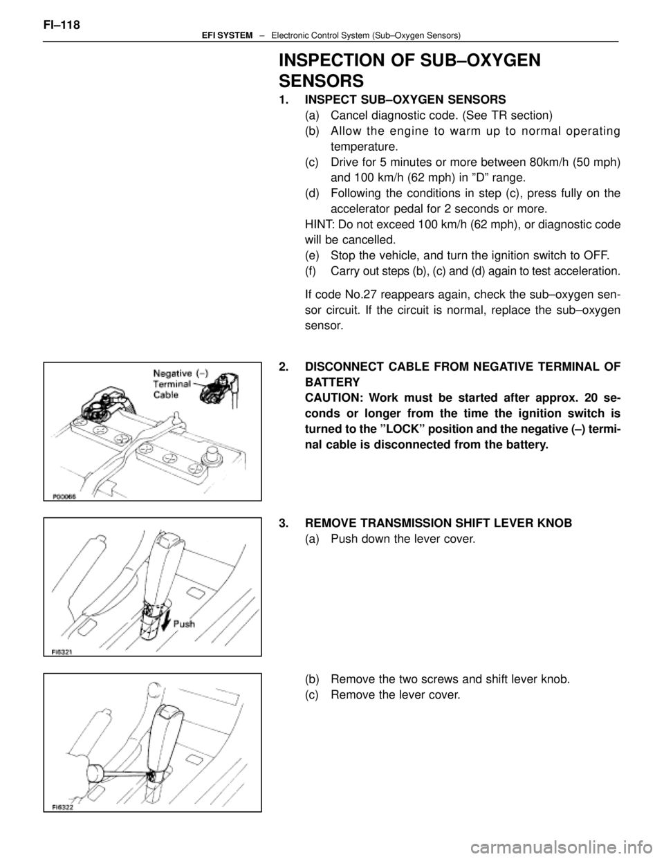
2. DISCONNECT CABLE FROM NEGATIVE TERMINAL OF BATTERY
CAUTION: Work must be started after approx. 20 se-
conds or longer from the time the ignition switch is
turned to the ºLOCKº position and the negative (±) termi-
nal cable is disconnected from the battery.
3. REMOVE TRANSMISSION SHIFT LEVER KNOB (a) Push down the lever cover.
(b) Remove the two screws and shift lever knob.
(c) Remove the lever cover.
FI±118
EFI SYSTEM
± Electronic Control System (Sub±Oxygen Sensors)
WhereEverybodyKnowsYourName
Page 1976 of 4087
13. REINSTALL UPPER CONSOLE PANELFit the console panel to the console box with the four clips.
14. REINSTALL CUP HOLDER Fit the cup holder to the console box.
15. REINSTALL TRANSMISSION SHIFT LEVER KNOB (a) Slide the lever cover on the lever shaft.
(b) Install the shift lever knob with the two screws.
(c) Attach the l ever cover to the lower side of the lever knob.
16. RECONNECT CABLE TO NEGATIVE TERMINAL OF BATTERY FI±121
EFI SYSTEM
± Electronic Control System (Sub±Oxygen Sensors)
WhereEverybodyKnowsYourName