Page 2191 of 4087

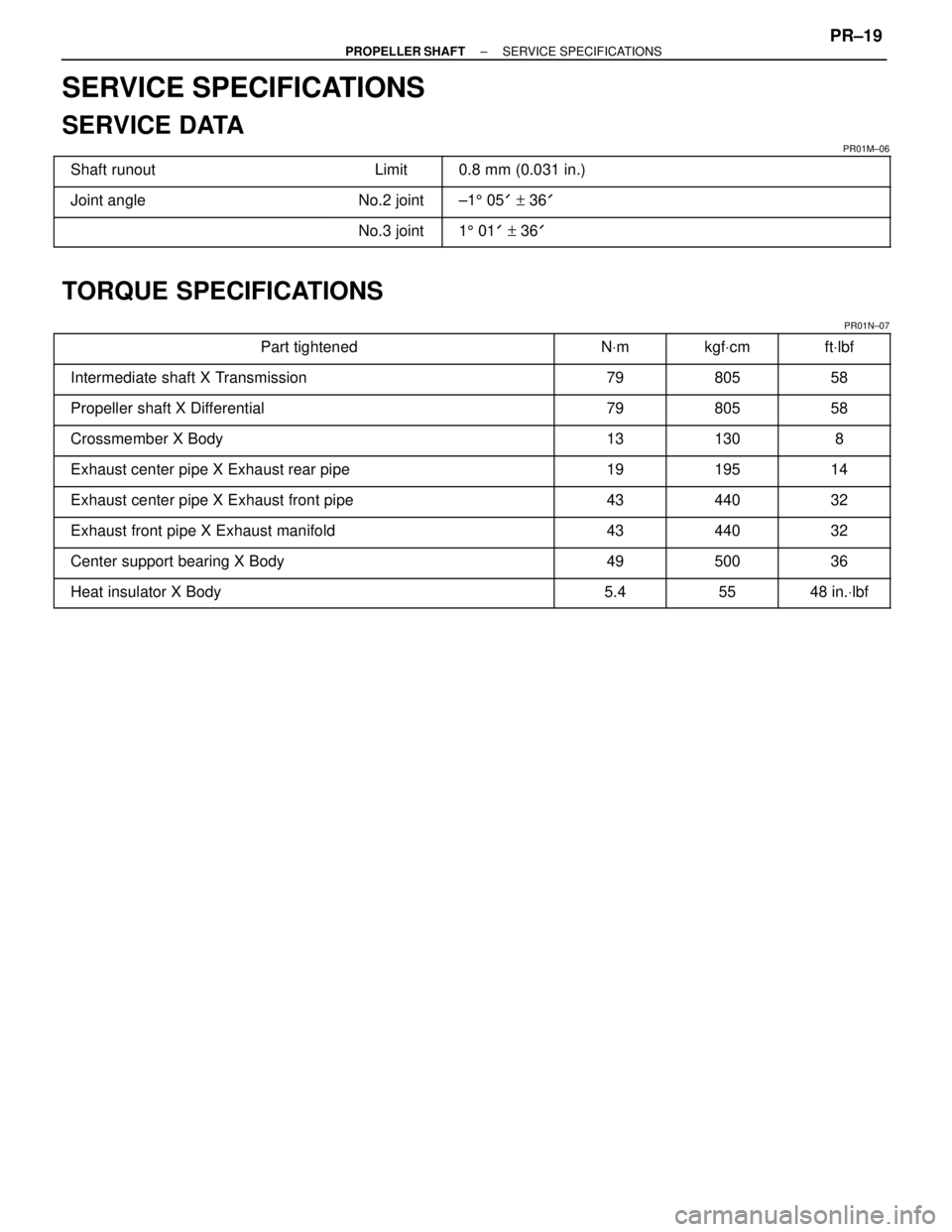
SERVICE SPECIFICATIONS
SERVICE DATA
PR01M±06������������ ������������Shaft runout������ ������Limit������������������\
�� ������������������\
��0.8 mm (0.031 in.)
������������ �
�����������
������������Joint angleNo.2 joint±1
5 05 ' + 36 '
������������ ������������������ ������No.3 joint������������������\
�� ������������������\
��15 01 ' + 36 '
TORQUE SPECIFICATIONS
PR01N±07������������������\
���� �
������������������\
���
������������������\
����Part tightened
����� �
����
�����N
Vm
������ �
�����
������kgf
Vcm
������ �
�����
������ft
Vlbf
������������������\
���� ������������������\
����Intermediate shaft X Transmission����� �����79������ ������805������ ������58
������������������\
���� ������������������\
����Propeller shaft X Differential����� �����79������ ������805������ ������58
������������������\
���� �
������������������\
���
������������������\
����Crossmember X Body����� �
����
�����13������ �
�����
������130������ �
�����
������8
������������������\
���� ������������������\
����Exhaust center pipe X Exhaust rear pipe����� �����19������ ������195������ ������14
������������������\
���� ������������������\
����Exhaust center pipe X Exhaust front pipe����� �����43������ ������440������ ������32
������������������\
���� ������������������\
����Exhaust front pipe X Exhaust manifold����� �����43������ ������440������ ������32������������������\
���� �
������������������\
���
������������������\
����Center support bearing X Body
����� �
����
�����49
������ �
�����
������500
������ �
�����
������36
������������������\
���� ������������������\
����Heat insulator X Body����� �����5.4������ ������55������ ������48 in.
Vlbf
±
PROPELLER SHAFT SERVICE SPECIFICATIONSPR±19
WhereEverybodyKnowsYourName
Page 2192 of 4087
DESCRIPTION
(SC300)
PR038±02
The propeller shaft is a 2±part type, each part consisting of a strong tube having a high centering and di-
mensional precision and a small diameter. The propeller shaft is connected to the transmission and the
differential via 3 joints. No.1 and No.2 joints are hooke universal joint.
NO.3 joint are made of flexible rubber couplings.
PR±20±
PROPELLER SHAFT DESCRIPTION (SC300)
WhereEverybodyKnowsYourName
Page 2197 of 4087

5. REMOVE PROPELLER SHAFT
(a) Place the matchmarks on the differential companion flangeand flexible coupling.
(b) Remove the 3 bolts inserted in the differential companion
flange.
NOTICE: The bolts inserted in the propeller shaft com-
panion flange should not be removed.
(c) Separate the flexible couplings from the differential side. HINT: If the flexible coupling can not be easily separated by
hand, insert a screwdriver into the bolt hole of the flexible cou-
pling, as shown in the illustration, then pry the coupling out.
NOTICE: Do not bring the screwdriver blade in direct
contact with the flexible coupling's rubber portion.
(d) Remove the 2 center support bearing set bolts and the adjusting washers.
HINT: Some vehicles are not equipped with an adjusting
washer.
NOTICE: When removing the set bolts, support the cen-
ter support bearing by hand so that the transmission and
intermediate shaft, and propeller shaft and differential,
remain in a straight line.
(e) Pull the yoke from the transmission.
(f) Insert SST in the transmission to prevent oil leakage. SST 09325±20010 (M/T)
09325±40010 (A/T)
±
PROPELLER SHAFT PROPELLER SHAFTPR±25
WhereEverybodyKnowsYourName
Page 2201 of 4087
(b) Remove SST.
(c) Insert the yoke into the transmission.
(d) Align the matchmarks and install the propeller shaft on thedifferential with the 3 bolts, washers and nuts.
NOTICE: Bolts should be inserted from the propeller
shaft side.
Torque: 79 N Vm (805 kgf Vcm, 58 ft Vlbf)
If using a new propeller shaft (w/ Phasemarks)
Install the propeller shaft phasemarks and differential phase-
marks so that their respective alignment phasemarks match.
If the propeller shaft phasemarks and differential phase-
marks do not align, install the propeller shaft and differential
alignment phasemarks are as close together as possible.
(w/o Phasemarks)
Install the propeller shaft.
(See page PR±28)
±
PROPELLER SHAFT PROPELLER SHAFTPR±29
WhereEverybodyKnowsYourName
Page 2228 of 4087

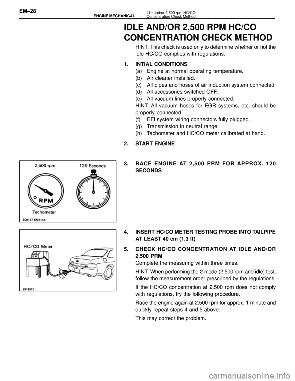
IDLE AND/OR 2,500 RPM HC/CO
CONCENTRATION CHECK METHOD
HINT: This check is used only to determine whether or not the
idle HC/CO complies with regulations.
1. INTIAL CONDITIONS (a) Engine at normal operating temperature.
(b) Air cleaner installed.
(c) All pipes and hoses of air induction system connected.
(d) All accessories switched OFF.
(e) All vacuum lines properly connected.
HINT: All vacuum hoses for EGR systems, etc. should be
properly connected.
(f) EFI system wiring connectors fully plugged.
(g) Transmission in neutral range.
(h) Tachometer and HC/CO meter calibrated at hand.
2. START ENGINE
3. RACE ENGINE AT 2,500 PRM FOR APPROX. 120 SECONDS
4. INSERT HC/CO METER TESTING PROBE INTO TAILPIPE AT LEAST 40 cm (1.3 ft)
5. CHECK HC/CO CONCENTRATION AT IDLE AND/OR 2,500 PRM
Complete the measuring within three times.
HINT: When performing the 2 mode (2,500 rpm and idle) test,
follow the measurement order prescribed by the regulations.
If the HC/CO concentration at 2,500 rpm does not comply
with regulations, try the following procedure.
Race the engine again at 2,500 rpm for approx. 1 minute and
quickly repeat steps 4 and 5 above.
This may correct the problem.
EM±28
±
ENGINE MECHANICAL Idle and/or 2,500 rpm HC/CO
Concentration Check Method
WhereEverybodyKnowsYourName
Page 2260 of 4087

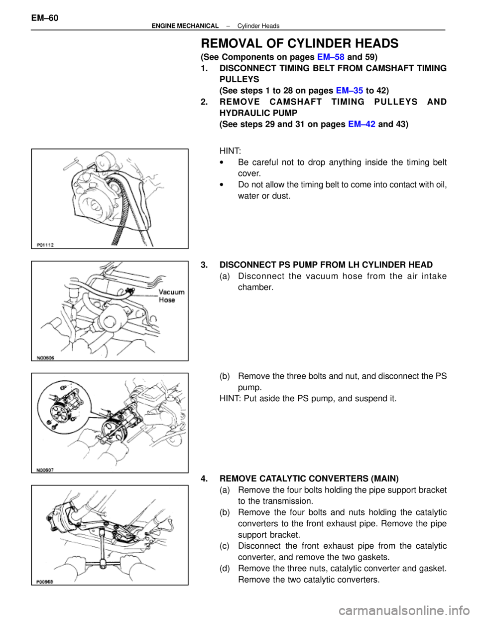
REMOVAL OF CYLINDER HEADS
(See Components on pages EM±58 and 59)
1. DISCONNECT TIMING BELT FROM CAMSHAFT TIMING PULLEYS
(See steps 1 to 28 on pages EM±35 to 42)
2. REMOVE CAMSHAFT TIMING PULLEYS AND HYDRAULIC PUMP
(See steps 29 and 31 on pages EM±42 and 43)
HINT:
w Be careful not to drop anything inside the timing belt
cover.
w Do not allow the timing belt to come into contact with oil,
water or dust.
3. DISCONNECT PS PUMP FROM LH CYLINDER HEAD (a) Disc onnect the vacuum hose from the air intake
chamber.
(b) Remove the three bolts and nut, and disconnect the PS pump.
HINT: Put aside the PS pump, and suspend it.
4. REMOVE CATALYTIC CONVERTERS (MAIN) (a) Remove the four bolts holding the pipe support bracketto the transmission.
(b) Remove the four bolts and nuts holding the catalytic converters to the front exhaust pipe. Remove the pipe
support bracket.
(c) Disconnect the front exhaust pipe from the catalytic
converter, and remove the two gaskets.
(d) Remove the three nuts, catalytic converter and gasket. Remove the two catalytic converters.
EM±60
±
ENGINE MECHANICAL Cylinder Heads
WhereEverybodyKnowsYourName
Page 2314 of 4087

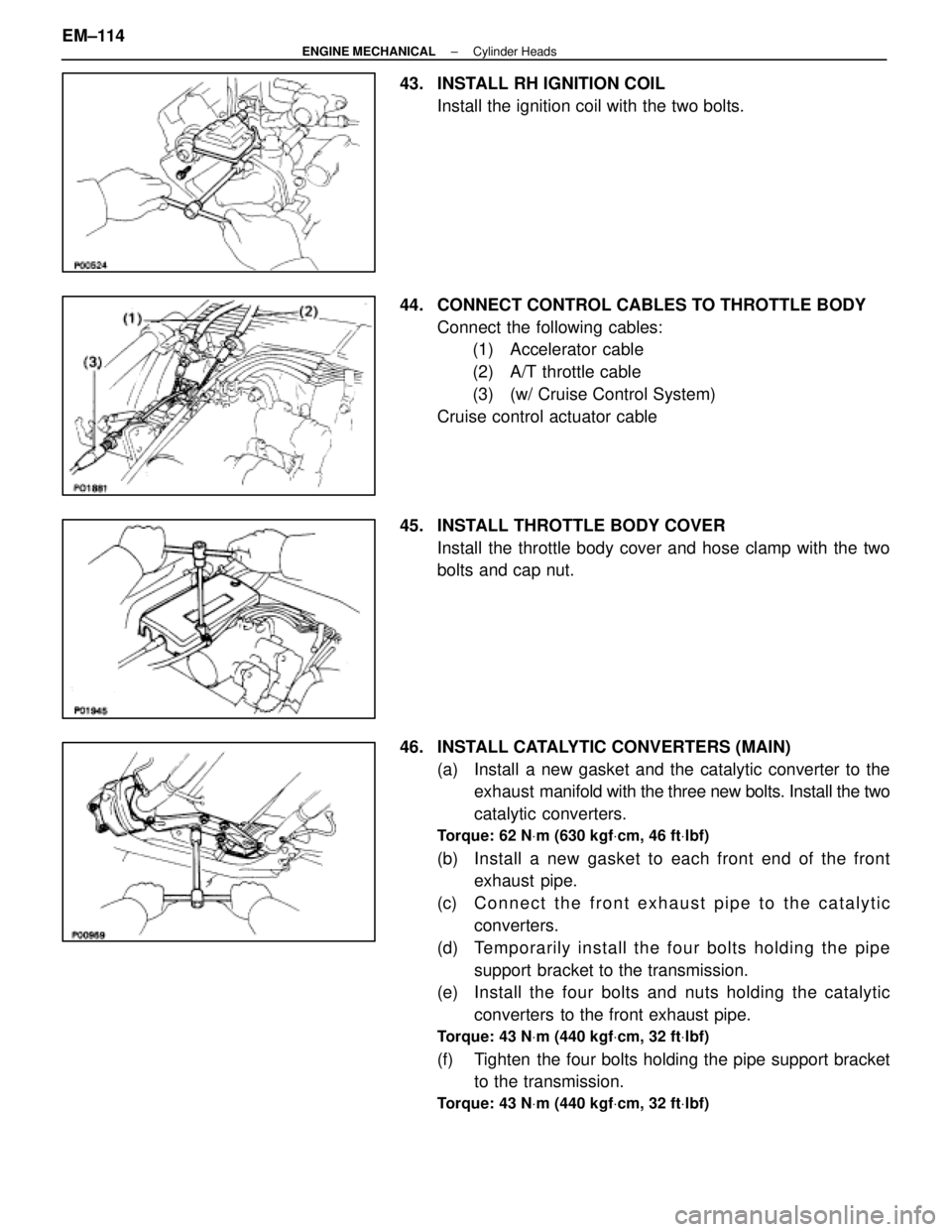
43. INSTALL RH IGNITION COILInstall the ignition coil with the two bolts.
44. CONNECT CONTROL CABLES TO THROTTLE BODY Connect the following cables:(1) Accelerator cable
(2) A/T throttle cable
(3) (w/ Cruise Control System)
Cruise control actuator cable
45. INSTALL THROTTLE BODY COVER Install the throttle body cover and hose clamp with the two
bolts and cap nut.
46. INSTALL CATALYTIC CONVERTERS (MAIN) (a) Install a new gasket and the catalytic converter to theexhaust manifold with the three new bolts. Install the two
catalytic converters.
Torque: 62 N Vm (630 kgf Vcm, 46 ft Vlbf)
(b) Install a new gasket to each front end of the front
exhaust pipe.
(c) C onnect the front exhaust pipe to the catalytic
converters.
(d) Te mp o ra rily in sta ll th e fo u r bo lts ho ld in g th e pip e support bracket to the transmission.
(e) Install the four bolts and nuts holding the catalytic
converters to the front exhaust pipe.
Torque: 43 N Vm (440 kgf Vcm, 32 ft Vlbf)
(f) Tighten the four bolts holding the pipe support bracket
to the transmission.
Torque: 43 N Vm (440 kgf Vcm, 32 ft Vlbf)
EM±114±
ENGINE MECHANICAL Cylinder Heads
WhereEverybodyKnowsYourName
Page 2316 of 4087
CYLINDER BLOCK
COMPONENTS FOR REMOVAL AND
INSTALLATION OF ENGINE WITH
TRANSMISSION
EM±116±
ENGINE MECHANICAL Cylinder Block
WhereEverybodyKnowsYourName