Page 2720 of 4087
CIRCUIT DESCRIPTION (Cont'd)
DIAGNOSIS CODE DETECTION DRIVING PATTERN
Purpose of the driving pattern.
(a) To simulate diag. code detecting condition after diag. code is recorded.
(b) To check that the malfunction is corrected when the repair is completed c\
onfirming that diag. code is nolonger detected.
�Initiate test mode (See page TR±12).
�Start engine and warm up.
�After engine is warmed up, let it idle for 3 min.
�With the A/C ON and transmission in D range (O/D OFF), drive at 40±\
70 mph for 4 min.
HINT: If a malfunction exists, the ºCHECKº engine warning light will light up at 1±4 min. of driving at 40±70 mph (64±112 km/h).
NOTICE: If the conditions in this test are not strictly followed, detection of the\
malfunction will not be possible.
Malfunction: Open in EGR gas temp. sensor circuit
±
ENGINE TROUBLESHOOTING Circuit InspectionTR±109
WhereEverybodyKnowsYourName
Page 2729 of 4087

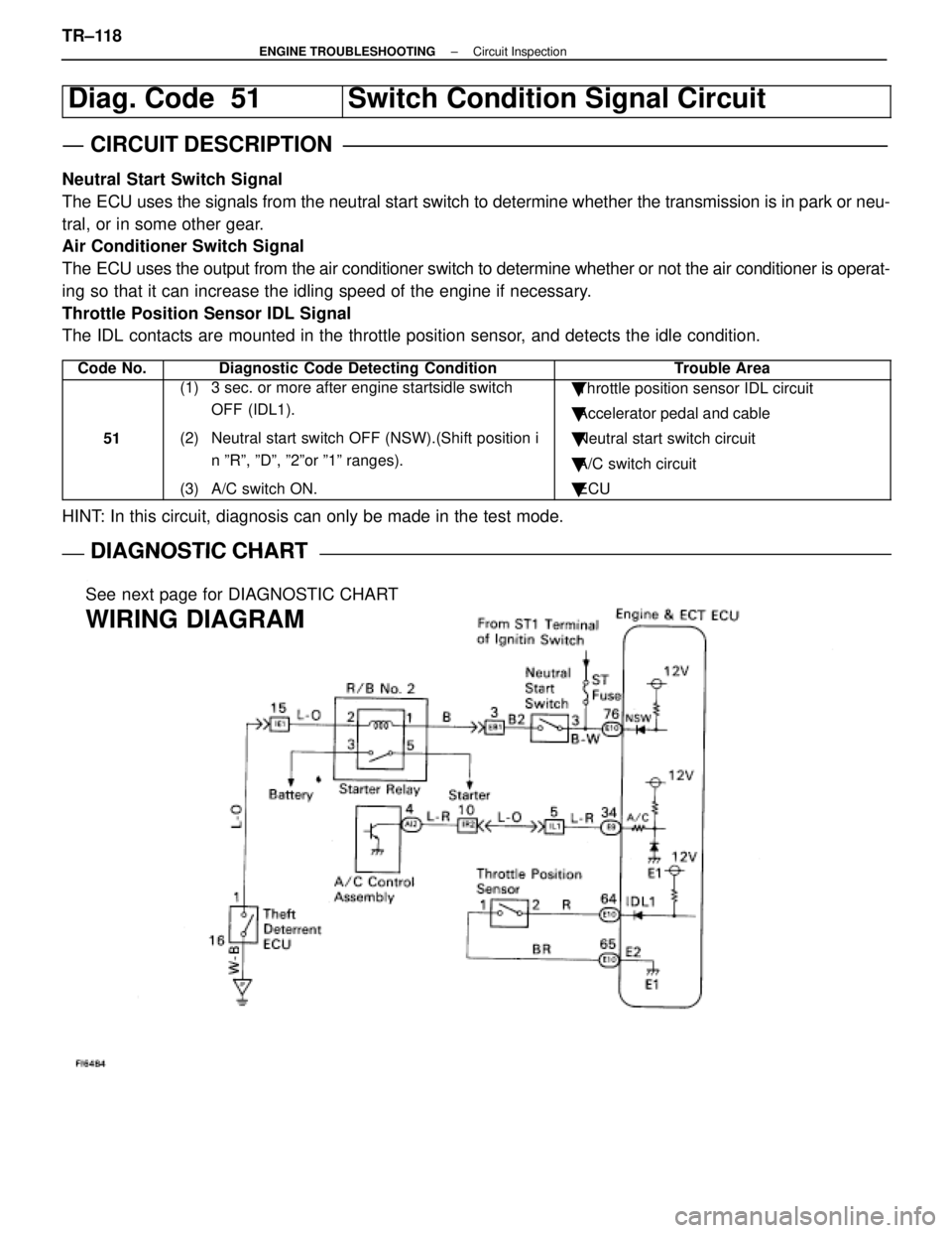
Diag. Code 51Switch Condition Signal Circuit
CIRCUIT DESCRIPTION
Neutral Start Switch Signal
The ECU uses the signals from the neutral start switch to determine whether\
the transmission is in park or neu-
tral, or in some other gear.
Air Conditioner Switch Signal
The ECU uses the output from the air conditioner switch to determine whethe\
r or not the air conditioner is operat-
ing so that it can increase the idling speed of the engine if necessary.
Throttle Position Sensor IDL Signal
The IDL contacts are mounted in the throttle position sensor, and detects the idle condition.
Code No.Diagnostic Code Detecting ConditionTrouble Area
51
(1) 3 sec. or more after engine startsidle switch OFF (IDL1).
(2) Neutral start switch OFF (NSW).(Shift position i n ºRº, ºDº, º2ºor º1º ranges).
(3) A/C switch ON.� Throttle position sensor IDL circuit
� Accelerator pedal and cable
� Neutral start switch circuit
� A/C switch circuit
� ECU
HINT: In this circuit, diagnosis can only be made in the test mode.
DIAGNOSTIC CHARTDIAGNOSTIC CHART
See next page for DIAGNOSTIC CHART
WIRING DIAGRAM
TR±118±
ENGINE TROUBLESHOOTING Circuit Inspection
WhereEverybodyKnowsYourName
Page 2789 of 4087

Coolant which is heated in the water jacket is pumped to the radiator, through which a cooling fan blows
air to cool the coolant as it passes through. Coolant which has been coo\
led is then sent back to the engine by
the water pump, where it cools the engine. The water jacket is a network of channels in the shell of the cylinder bloc\
k and cylinderhead through which
coolant passes. It is designed to provide adequate cooling through the cylinders and combus\
tion chambers
which become heated during engine operation.
RADIATOR The radiator performs the function of cooling the coolant which has pass\
ed through the waterjacket and
become hot, and it is mounted in the front of the vehicle. The radiator consis\
ts of an upper tank and lower tank,
and a core which connects the two tanks. The upper tank contains the inlet \
for coolant from the water jacket
and the filler inlet. It also has a hose attached through which excess cool\
ant or steam can flow. The lower tank
contains the outlet for coolant and drain plug. The core contains many t\
ubes through which coolant flows from
the upper tank to the lower tank as well as cooling fins which radiate heat\
away from the coolant in the tubes.
The air sucked through the radiator by the cooling fan, as well as the wind generated by the ve\
hicle's travel,
passes through the radiator, cooling the coolant. Models with automatic transmission include an aut\
omatic
transmission fluid cooler built into the lower tank of the radiator. A cooling fan is mounted behind radiator to assist
the flow of air through the radiator. When the coolant temperature is low, the fan operates slowly to help the warm
up, and when the coolant temperature becomes high, the fan speed is increas\
ed to provide the air flow required
for cooling.
RADIATOR CAP (on Reservoir Tank)
The radiator cap is a pressure type cap which seals the radiator, resulting in pressurization of the radiator
as the coolant expands. The pressurization prevents the coolant from boi\
ling even when the coolant tempera-
ture exceeds 100 5C (212 5F). A relief valve (pressurization valve) and a vacuum valve (negati\
ve pressure valve)
are built into the radiator cap. The relief valve opens and lets steam esca\
pe through the overflow pipe when
the pressure generated inside the cooling system exceeds the limit (coolant temperature: 110±120 5C
(230±248 5F) pressure; 29.4±98.1 kPa (0.3±1.0 kgf/cm2, 4.3±14.2 psi)). The vacuum v\
alve opens to alleviate
the vacuum which develops in the coolant system after the engine is stopped\
and the coolant temperature
drops.
RESERVOIR TANK The purpose of the reservoir tank is to catch coolant overflows created by \
volumetrix expansion when the
coolant temperature increases. The cap of the reservoir tank is a pressure type\
which prevents deterioration
of the LLC (Long Life Coolant) caused by contact with atmospheric air, increases vaporization performance and
reduces loss of the coolant volume.
WATER PUMP The water pump is mounted on the front of the cylinder block and driven by t\
he reverse side of the timing
belt.
THERMOSTAT The thermostat has a wax type by±pass valve and is mounted in the wat\
er inlet housing. The thermostat
begins to open at the temperature of 80 5C (180 5F). When the coolant temperature is low, the valve closes to
prevent coolant flow to the radiator, thus permitting the engine to warm up rapidly. When the by±pass valve
opens the by±pass circuit, the engine coolant continues to circulate \
inside the engine, quickly and uniformly
warming up to the appropriate temperature. When the coolant temperature is high\
, the valve opens and coolant
flows to the radiator where it is cooled. When the wax inside the thermostat \
is heated, it expands and thus
creates pressure which overpowers the force of the spring which keeps the valve\
closed. When the wax cools,
its contraction causes the force of the spring to take effect once more, closing the valve.
ELECTRONICALLY CONTROLLED HYDRAULIC COOLING FAN (See page CO±22)
±
COOLIING SYSTEM DescriptionCO±3
WhereEverybodyKnowsYourName
Page 2807 of 4087
9. FILL ENGINE WITH COOLANT (See page CO±7)
10. FILL COOLING FAN RESERVOIR TANK WITH FLUID (See pages CO±23 and 24)
11. CHECK AUTOMATIC TRANSMISSION FLUID LEVEL
(See page MA±11)
NOTICE: Do not overfill.
12. START ENGINE AND CHECK FOR LEAKS
13. INSTALL ENGINE UNDER COVER
±
COOLIING SYSTEM RadiatorCO±21
WhereEverybodyKnowsYourName
Page 2868 of 4087
INSPECTION OF EGR SYSTEM (USA
Spec.)
INSPECT SYSTEM OPERATION
(a) Using SST, connect terminals TE1 and E1 of the check(ºDIAGNOSISº) connector.
SST 09843±18020
(b) Keep the engine at 3,500 rpm.
(c) Set the transmission shift lever to the ºNº position.
(d) Remove the SST from the check connector.
SST 09843±18020
(e) Check whether the engine rpm increases 100±300 rpm under the following conditions.
Coolant temp.
Below 53 5C (127 5F) No increase
Above 55 5C (131 5F) Increases
±
EMISSION CONTROL SYSTEMS Exhaust Gas Recirculation (EGR) SystemEC±17
WhereEverybodyKnowsYourName
Page 2869 of 4087
INSPECTION OF EGR SYSTEM
(Exc. USA Spec.)
1. CHECK AND CLEAN FILTERS IN EGR VACUUMMODULATOR
(a) Remove the cap and filter.
(b) Check the filter for contamination or damage.
(c) Using compressed air, clean the filters.
(d) Reinstall the filter and cap.
HINT: Install the filter with the coarser surface facing the at-
mospheric side (outward).
2. INSPECT SYSTEM OPERATION (a) Using SST, connect terminals TE1 and E1 of the check
(ºDIAGNOSISº) connector.
SST 09843±18020
(b) Keep the engine at 3,500 rpm.
(c) Set the transmission shift lever to the ºNº position.
(d) Remove the SST from the check connector.
SST 09843±18020
(e) Check whether the engine rpm increases 100±300 rpm under the following conditions:
Coolant temp.
Below 53 5C (127 5F) No increase
Above 55 5C (131 5F) Increases
EC±18
±
EMISSION CONTROL SYSTEMS Exhaust Gas Recirculation (EGR) System
WhereEverybodyKnowsYourName
Page 2879 of 4087

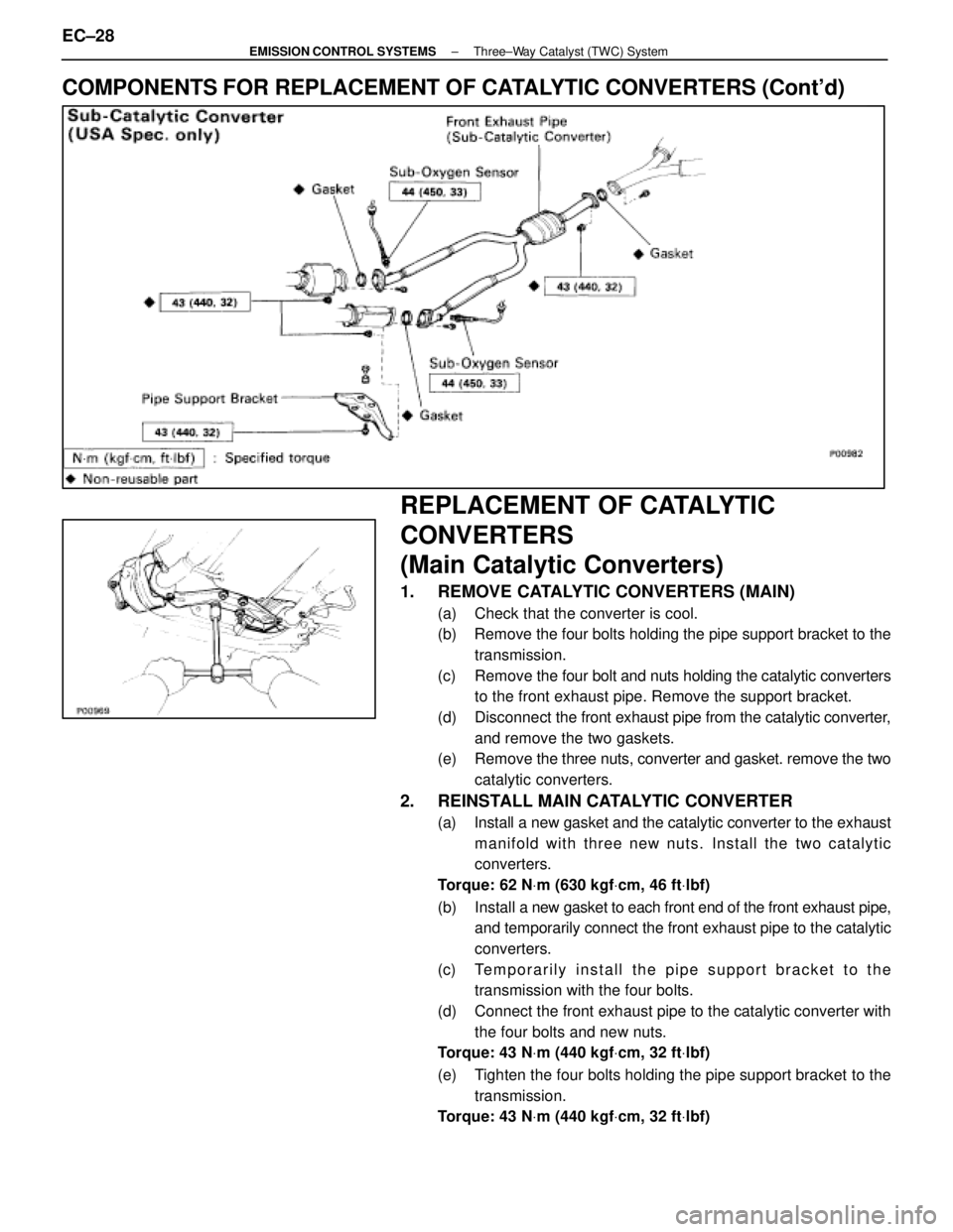
COMPONENTS FOR REPLACEMENT OF CATALYTIC CONVERTERS (Cont'd)
REPLACEMENT OF CATALYTIC
CONVERTERS
(Main Catalytic Converters)
1. REMOVE CATALYTIC CONVERTERS (MAIN)
(a) Check that the converter is cool.
(b) Remove the four bolts holding the pipe support bracket to thetransmission.
(c) Remove the four bolt and nuts holding the catalytic converters
to the front exhaust pipe. Remove the support bracket.
(d) Disconnect the front exhaust pipe from the catalytic converter,
and remove the two gaskets.
(e) Remove the three nuts, converter and gasket. remove the two
catalytic converters.
2. REINSTALL MAIN CATALYTIC CONVERTER
(a) Install a new gasket and the catalytic converter to the exhaust manifold with three new nuts. Install the two catalytic
converters.
Torque: 62 N Vm (630 kgf Vcm, 46 ft Vlbf)
(b) Install a new gasket to each front end of the front exhaust pipe,
and temporarily connect the front exhaust pipe to the catalytic
converters.
(c) Temporarily install the pipe support bracket to the transmission with the four bolts.
(d) Connect the front exhaust pipe to the catalytic converter with the four bolts and new nuts.
Torque: 43 N Vm (440 kgf Vcm, 32 ft Vlbf)
(e) Tighten the four bolts holding the pipe support bracket to the transmission.
Torque: 43 N Vm (440 kgf Vcm, 32 ft Vlbf)
EC±28±
EMISSION CONTROL SYSTEMS Three±Way Catalyst (TWC) System
WhereEverybodyKnowsYourName
Page 2880 of 4087

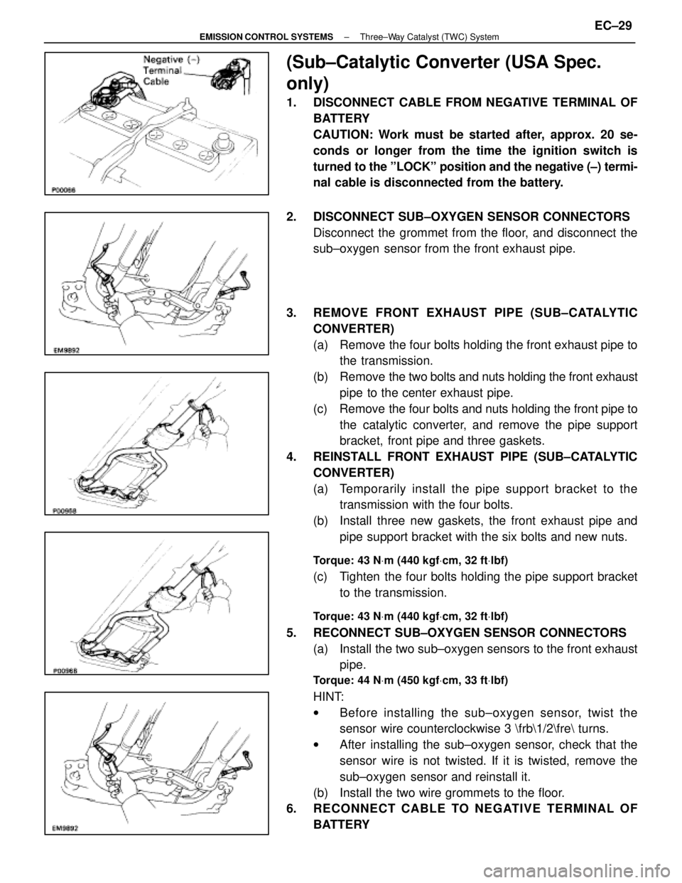
(Sub±Catalytic Converter (USA Spec.
only)
1. DISCONNECT CABLE FROM NEGATIVE TERMINAL OFBATTERY
CAUTION: Work must be started after, approx. 20 se-
conds or longer from the time the ignition switch is
turned to the ºLOCKº position and the negative (±) termi-
nal cable is disconnected from the battery.
2. DISCONNECT SUB±OXYGEN SENSOR CONNECTORS Disconnect the grommet from the floor, and disconnect the
sub±oxygen sensor from the front exhaust pipe.
3. REMOVE FRONT EXHAUST PIPE (SUB±CATALYTIC CONVERTER)
(a) Remove the four bolts holding the front exhaust pipe tothe transmission.
(b) Remove the two bolts and nuts holding the front exhaust
pipe to the center exhaust pipe.
(c) Remove the four bolts and nuts holding the front pipe to the catalytic converter, and remove the pipe support
bracket, front pipe and three gaskets.
4. REINSTALL FRONT EXHAUST PIPE (SUB±CATALYTIC CONVERTER)
(a) Temporarily install the pipe support bracket to thetransmission with the four bolts.
(b) Install three new gaskets, the front exhaust pipe and pipe support bracket with the six bolts and new nuts.
Torque: 43 N Vm (440 kgf Vcm, 32 ft Vlbf)
(c) Tighten the four bolts holding the pipe support bracket
to the transmission.
Torque: 43 N Vm (440 kgf Vcm, 32 ft Vlbf)
5. RECONNECT SUB±OXYGEN SENSOR CONNECTORS
(a) Install the two sub±oxygen sensors to the front exhaustpipe.
Torque: 44 N Vm (450 kgf Vcm, 33 ft Vlbf)
HINT:
w Before installing the s ub±oxygen sensor, twist the
sensor wire counterclockwise 3 \frb\1/2\fre turns.
w After installing the sub±oxygen sensor, check that the
sensor wire is not twisted. If it is twisted, remove the
sub±oxygen sensor and reinstall it.
(b) Install the two wire grommets to the floor.
6. RECONNECT CABLE TO NEGATIVE TERMINAL OF
BATTERY
±
EMISSION CONTROL SYSTEMS Three±Way Catalyst (TWC) SystemEC±29
WhereEverybodyKnowsYourName