Page 2881 of 4087
SERVICE SPECIFICATIONS
SERVICE DATA
VSVResistance30±34 �
for EVAP
VSVResistance33±39 �
for EGR
EGR valveResistance19.9±23.4 �
(CALIF. only)
TORQUE SPECIFICATIONS
Part tightenedNVmkgf Vcmft Vlbf
VSV for EGR X Air intake chamber (Exc. USA Spec.)1818513
EGR valve X Air intake chamber18185 13
Catalytic converter (Main) X Exhaust manifold62630 46
Catalytic converter (Main) X Front exhaust pipe43440 32
Front exhaust pipe support bracket X Transmission43440 32
Front exhaust pipe X Center exhaust pipe43440 32
Main oxygen sensor X Front exhaust pipe4445033
EC±30±
EMISSION CONTROL SYSTEMS Servuce Specifications
WhereEverybodyKnowsYourName
Page 3017 of 4087
POWER STEERING ECU
1. JACK UP VEHICLE AND SUPPORT IT ON STANDS
2. START ENGINE
3. MEASURE VOLTAGE OF ECU
(a) Using a voltmeter, measure the voltage between ECUterminals SOL � and GND while the engine is idling.
Standard voltage:
0.3±0.5 V
(b) Place the transmission in gear and while running at about 37
mph (60 km/h), measure the voltage between ECU terminals
SOL � and GND.
Standard voltage:
Voltage measured in (a) above, minus
(IUZ±FE Engine)
0.07±0.02 V
(2JZ±FE Engine)
0.05±0.18 V
If no voltage, try another ECU.
4. LOWER VEHICLE
SR±168
±
STEERING POWER STEERING
WhereEverybodyKnowsYourName
Page 3385 of 4087

Diagnosis Inspection (Test Mode)
Compared to the normal mode, the test mode has high sensing
ability to detect malfunctions.
It can also detect malfunctions in the starter signal circuit, the IDL
contact signal of the throttle position sensor, air conditioner signal
and neutral start switch signal.
Furthermore, the same diagnostic items which are detected in the
normal mode can also be detected in the test mode.
DIAGNOSTIC CODE CHECK
1. Initial conditions.(a) Battery voltage 11 V or more.
(b) Throttle valve fully closed (throttle position sensor IDLpoints closed).
(c) Transmission in neutral position.
(d) Air conditioner switched off.
2. Turn ignition switch off.
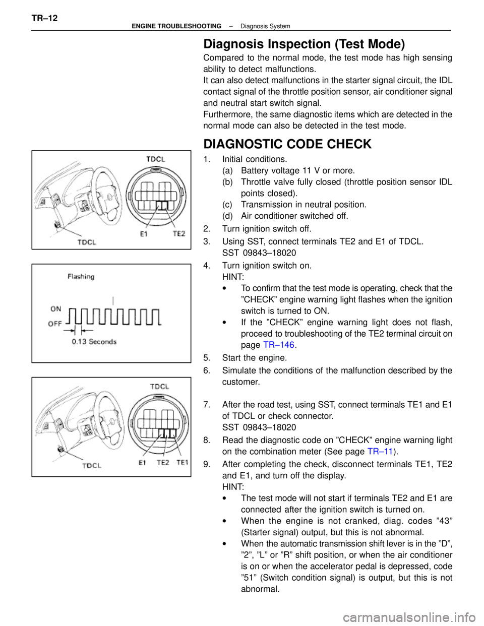
3. Using SST, connect terminals TE2 and E1 of TDCL. SST 09843±18020
4. Turn ignition switch on. HINT:
wTo confirm that the test mode is operating, check that the
ºCHECKº engine warning light flashes when the ignition
switch is turned to ON.
w If the ºCHECKº engine warning light does not flash,
proceed to tro ubleshooting of the TE2 terminal circuit on
page TR±146 .
5. Start the engine.
6. Simulate the conditions of the malfunction described by the customer.
7. After the road test, using SST, connect terminals TE1 and E1
of TDCL or check connector.
SST 09843±18020
8. Read the diagnostic code on ºCHECKº engine warning light on the combination meter (See page TR±11).
9. After completing the check, disconnect terminals TE1, TE2 and E1, and turn off the display.
HINT:
wThe test mode will not start if terminals TE2 and E1 are
connected after the ignition switch is turned on.
w When the engine is not cranked, diag. codes º43º
(Starter signal) output, but this is not abnormal.
w When the automatic transmission shift lever is in the ºDº,
º2º, ºLº or ºRº shift position, or when the air conditioner
is on or when the accelerator pedal is depressed, code
º51º (Switch condition signal) is output, but this is not
abnormal.
TR±12
±
ENGINE TROUBLESHOOTING Diagnosis System
WhereEverybodyKnowsYourName
Page 3398 of 4087

OKNG
OKNG
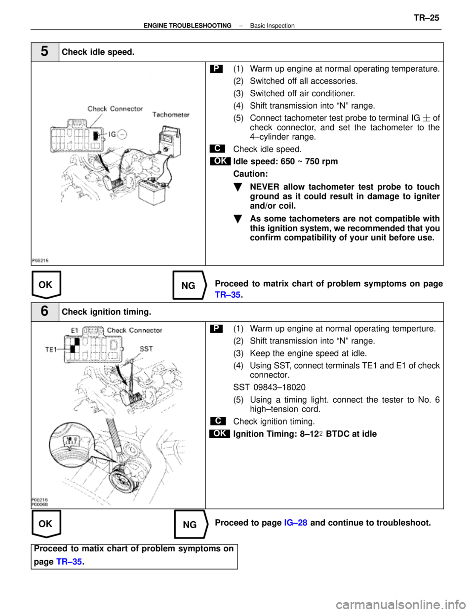
5Check idle speed.
C
OK
P(1) Warm up engine at normal operating temperature.
(2) Switched off all accessories.
(3) Switched off air conditioner.
(4) Shift transmission into ªNº range.
(5) Connect tachometer test probe to terminal IG � of
check connector, and set the tachometer to the
4±cylinder range.
Check idle speed.
Idle speed: 650 ~ 750 rpm
Caution:
�NEVER allow tachometer test probe to touch
ground as it could result in damage to igniter
and/or coil.
�As some tachometers are not compatible with
this ignition system, we recommended that you
confirm compatibility of your unit before use.
Proceed to matrix chart of problem symptoms on page
TR±35 .
6Check ignition timing.
C
OK
P(1) Warm up engine at normal operating temperture.
(2) Shift transmission into ªNº range.
(3) Keep the engine speed at idle.
(4) Using SST, connect terminals TE1 and E1 of check
connector.
SST 09843±18020
(5) Using a timing light. connect the tester to No. 6 high±tension cord.
Check ignition timing.
Ignition Timing: 8±12 � BTDC at idle
Proceed to page IG±28 and continue to troubleshoot.
Proceed to matix chart of problem symptoms on
page TR±35 .
±
ENGINE TROUBLESHOOTING Basic InspectionTR±25
WhereEverybodyKnowsYourName
Page 3455 of 4087
Are there any other codes (besides
Code 16) being output?
Replace engine (& ECT) ECU.
Go to relevant diag. code
chart.
Diag. Code 16ECT Control Signal Malfunction
CIRCUIT DESCRIPTION
The signal from the ECT CPU retards the ignition timing of the engine durin\
g ECT gear shifting, thus momentarily
reducing torque output of the engine for smooth clutch operation inside the transmission and reduced shift
shock.
If the ECU records the diagnostic code º16º in memory, it prohibits the torque control of the ECT which performs
smooth gear shifting.
DTC No.DTC Detecting ConditionTrouble Area
16Fault in communications between the engine CPU and
ECT CPU in the ECU.� ECU
If the ECU records the diagnostic trouble code º16º in memory, it prohibits the torque control of the ECT which
performs smooth gear shifting.
DIAGNOSTIC CHARTDIAGNOSTIC CHART
TR±58±
ENGINE TROUBLESHOOTING Circuit Inspection
WhereEverybodyKnowsYourName
Page 3460 of 4087
Diag. Code 16ECT Control Signal Malfunction
CIRCUIT DESCRIPTION
The signal from the ECT CPU retards the ignition timeing of the engine duri\
ng ECT gear shifting, thus mo-
mentarily reducing torque output of the engine for smooth clutch operati\
on inside the transmission and re-
duced shift shock.
Code No.Diagnostic Code Detecting ConditionTrouble Area
16Fault in communications between the engine
CPU and ECT CPU in the ECU.�ECU
If the ECU records the diagnostic code ª16º in memory, it prohibits the torque control of the ECT which per-
forms smooth gear shifting.
DIAGNOSTIC CHARTDIAGNOSTIC CHART
Are there any other codes (besides Code 16)
being output?
Replace engine & ECT ECU. Go to relevant diag. code chart.
±
ENGINE TROUBLESHOOTING Circuit InspectionTR±61
WhereEverybodyKnowsYourName
Page 3462 of 4087

CIRCUIT DESCRIPTION (Cont'd)
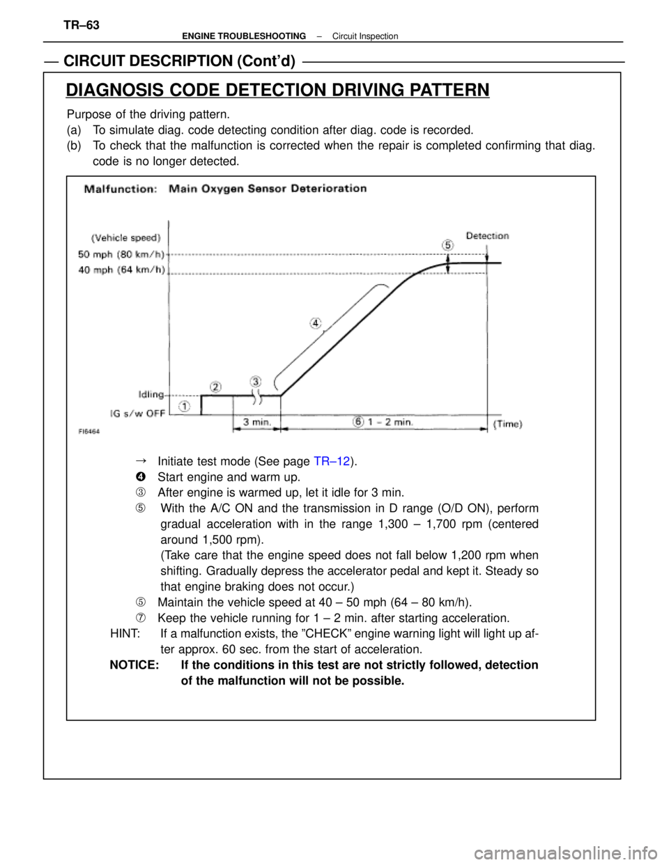
Purpose of the driving pattern.
(a) To simulate diag. code detecting condition after diag. code is recorded.
(b) To check that the malfunction is corrected when the repair is completed confirming that diag.code is no longer detected.
DIAGNOSIS CODE DETECTION DRIVING PATTERN
��Initiate test mode (See page TR±12).
��Start engine and warm up.
��After engine is warmed up, let it idle for 3 min.
�With the A/C ON and the transmission in D range (O/D ON), perform
gradual acceleration with in the range 1,300 ± 1,700 rpm (centered
around 1,500 rpm).
(Take care that the engine speed does not fall below 1,200 rpm when
shifting. Gradually depress the accelerator pedal and kept it. Steady so
that engine braking does not occur.)
��Maintain the vehicle speed at 40 ± 50 mph (64 ± 80 km/h).
��Keep the vehicle running for 1 ± 2 min. after starting acceleration.
HINT: If a malfunction exists, the ºCHECKº engine warning light will light\
up af-
ter approx. 60 sec. from the start of acceleration.
NOTICE: If the conditions in this test are not strictly followed, detection of the malfunction will not be possible.
TR±63
±
ENGINE TROUBLESHOOTING Circuit Inspection
WhereEverybodyKnowsYourName
Page 3496 of 4087

CIRCUIT DESCRIPTION (Cont'd)
DIAGNOSIS CODE DETECTION DRIVING PATTERN
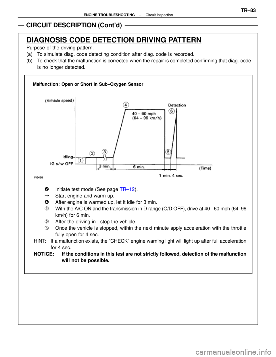
Purpose of the driving pattern.
(a) To simulate diag. code detecting condition after diag. code is recorded.
(b) To check that the malfunction is corrected when the repair is completed co\
nfirming that diag. codeis no longer detected.
Malfunction: Open or Short in Sub±Oxygen Sensor
�Initiate test mode (See page TR±12).
�Start engine and warm up.
�After engine is warmed up, let it idle for 3 min.
�With the A/C ON and the transmission in D range (O/D OFF), drive at 40 ±\
60 mph (64±96
km/h) for 6 min.
�After the driving in , stop the vehicle.
�Once the vehicle is stopped, within the next minute apply acceleration w\
ith the throttle
fully open for 4 sec.
HINT: If a malfunction exists, the ºCHECKº engine warning light will light\
up after full acceleration for 4 sec.
NOTICE: If the conditions in this test are not strictly followed, detection of the\
malfunction will not be possible.
±
ENGINE TROUBLESHOOTING Circuit InspectionTR±83
WhereEverybodyKnowsYourName