Page 1758 of 4087

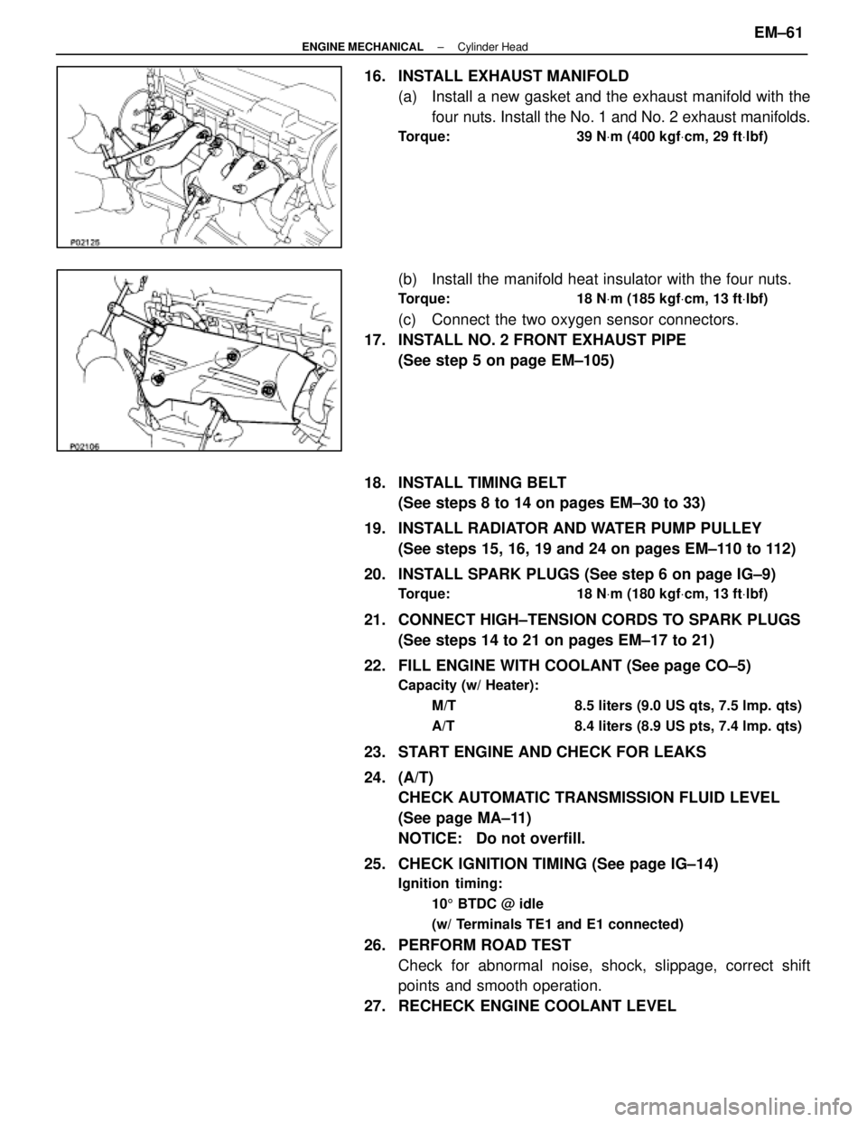
16. INSTALL EXHAUST MANIFOLD(a) Install a new gasket and the exhaust manifold with thefour nuts. Install the No. 1 and No. 2 exhaust manifolds.
Torque: 39 N Vm (400 kgf Vcm, 29 ft Vlbf)
(b) Install the manifold heat insulator with the four nuts.
Torque: 18 N Vm (185 kgf Vcm, 13 ft Vlbf)
(c) Connect the two oxygen sensor connectors.
17. INSTALL NO. 2 FRONT EXHAUST PIPE (See step 5 on page EM±105)
18. INSTALL TIMING BELT (See steps 8 to 14 on pages EM±30 to 33)
19. INSTALL RADIATOR AND WATER PUMP PULLEY (See steps 15, 16, 19 and 24 on pages EM±110 to 112)
20. INSTALL SPARK PLUGS (See step 6 on page IG±9)
Torque: 18 N Vm (180 kgf Vcm, 13 ft Vlbf)
21. CONNECT HIGH±TENSION CORDS TO SPARK PLUGS
(See steps 14 to 21 on pages EM±17 to 21)
22. FILL ENGINE WITH COOLANT (See page CO±5)
Capacity (w/ Heater): M/T 8.5 liters (9.0 US qts, 7.5 lmp. qts)
A/T 8.4 liters (8.9 US pts, 7.4 lmp. qts)
23. START ENGINE AND CHECK FOR LEAKS
24. (A/T)CHECK AUTOMATIC TRANSMISSION FLUID LEVEL
(See page MA±11)
NOTICE: Do not overfill.
25. CHECK IGNITION TIMING (See page IG±14)
Ignition timing: 105 BTDC @ idle
(w/ Terminals TE1 and E1 connected)
26. PERFORM ROAD TEST Check for abnormal noise, shock, slippage, correct shift
points and smooth operation.
27. RECHECK ENGINE COOLANT LEVEL
±
ENGINE MECHANICAL Cylinder HeadEM±61
WhereEverybodyKnowsYourName
Page 1761 of 4087

REMOVAL OF CYLINDER HEADS
(See Components on pages EM±58 and 59)
1. DISCONNECT TIMING BELT FROM CAMSHAFT TIMING PULLEYS
(See steps 1 to 28 on pages EM±35 to 42)
2. REMOVE CAMSHAFT TIMING PULLEYS AND HYDRAULIC PUMP
(See steps 29 and 31 on pages EM±42 and 43)
HINT:
w Be careful not to drop anything inside the timing belt
cover.
w Do not allow the timing belt to come into contact with oil,
water or dust.
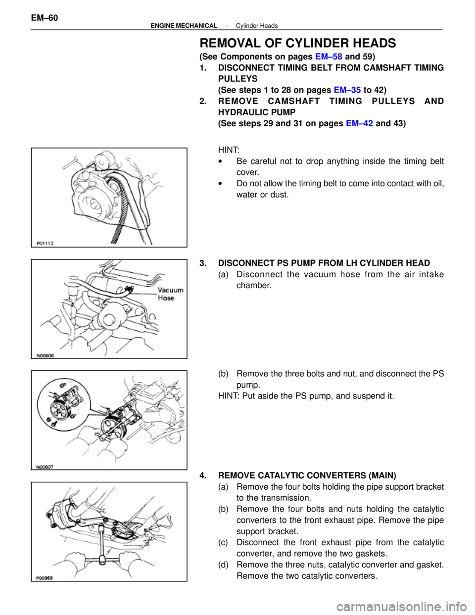
3. DISCONNECT PS PUMP FROM LH CYLINDER HEAD (a) Disc onnect the vacuum hose from the air intake
chamber.
(b) Remove the three bolts and nut, and disconnect the PS pump.
HINT: Put aside the PS pump, and suspend it.
4. REMOVE CATALYTIC CONVERTERS (MAIN) (a) Remove the four bolts holding the pipe support bracketto the transmission.
(b) Remove the four bolts and nuts holding the catalytic converters to the front exhaust pipe. Remove the pipe
support bracket.
(c) Disconnect the front exhaust pipe from the catalytic
converter, and remove the two gaskets.
(d) Remove the three nuts, catalytic converter and gasket. Remove the two catalytic converters.
EM±60
±
ENGINE MECHANICAL Cylinder Heads
WhereEverybodyKnowsYourName
Page 1815 of 4087

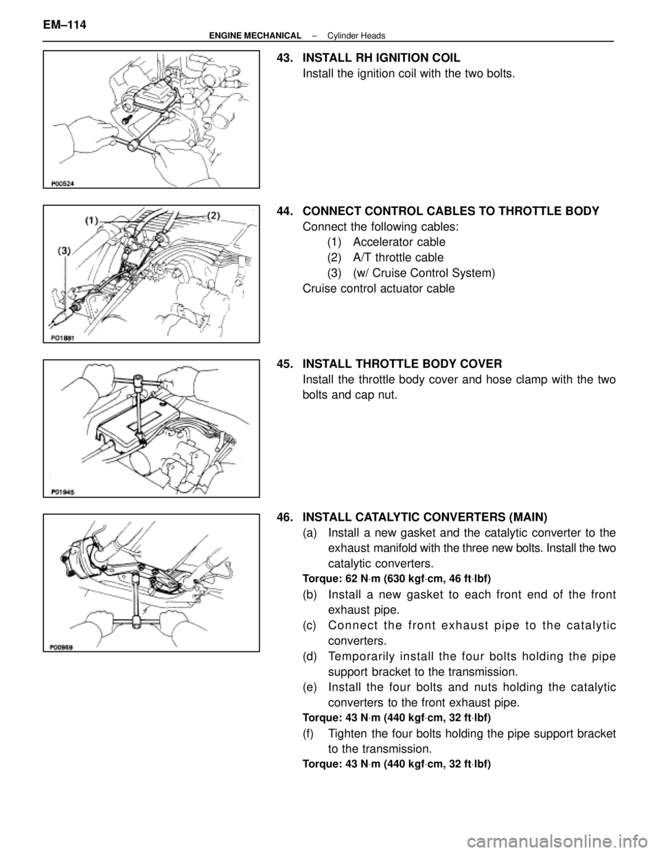
43. INSTALL RH IGNITION COILInstall the ignition coil with the two bolts.
44. CONNECT CONTROL CABLES TO THROTTLE BODY Connect the following cables:(1) Accelerator cable
(2) A/T throttle cable
(3) (w/ Cruise Control System)
Cruise control actuator cable
45. INSTALL THROTTLE BODY COVER Install the throttle body cover and hose clamp with the two
bolts and cap nut.
46. INSTALL CATALYTIC CONVERTERS (MAIN) (a) Install a new gasket and the catalytic converter to theexhaust manifold with the three new bolts. Install the two
catalytic converters.
Torque: 62 N Vm (630 kgf Vcm, 46 ft Vlbf)
(b) Install a new gasket to each front end of the front
exhaust pipe.
(c) C onnect the front exhaust pipe to the catalytic
converters.
(d) Te mp o ra rily in sta ll th e fo u r bo lts ho ld in g th e pip e support bracket to the transmission.
(e) Install the four bolts and nuts holding the catalytic
converters to the front exhaust pipe.
Torque: 43 N Vm (440 kgf Vcm, 32 ft Vlbf)
(f) Tighten the four bolts holding the pipe support bracket
to the transmission.
Torque: 43 N Vm (440 kgf Vcm, 32 ft Vlbf)
EM±114±
ENGINE MECHANICAL Cylinder Heads
WhereEverybodyKnowsYourName
Page 1817 of 4087
CYLINDER BLOCK
COMPONENTS FOR REMOVAL AND
INSTALLATION OF ENGINE WITH
TRANSMISSION
EM±62±
ENGINE MECHANICAL Cylinder Block
WhereEverybodyKnowsYourName
Page 1818 of 4087
COMPONENTS FOR REMOVAL AND
INSTALLATION OF ENGINE WITH
TRANSMISSION (Cont'd)
±
ENGINE MECHANICAL Cylinder BlockEM±63
WhereEverybodyKnowsYourName
Page 1819 of 4087
COMPONENTS FOR REMOVAL AND
INSTALLATION OF ENGINE WITH
TRANSMISSION (Cont'd)
REMOVAL OF ENGINE WITH
TRANSMISSION
1. REMOVE BATTERYCAUTION: Turn the ignition switch to ºLOCKº. Discon-
nect the cable from the negative (±) terminal of the bat-
tery. Wait at least 20 seconds before proceeding with
work.
2. REMOVE ENGINE UNDER COVER
3. DRAIN ENGINE COOLANT
4. DISCONNECT CONTROL CABLES FROM THROTTLE BODY
Disconnect the following cables:(1) Accelerator cable
(2) (A/T)Throttle control cable
(3) Cruise control actuator cable
EM±64
±
ENGINE MECHANICAL Cylinder Block
WhereEverybodyKnowsYourName
Page 1823 of 4087
(p) Remove the bolt holding the engine wire protector fromthe heater valve bracket.
(q) Remove the two nuts holding the engine wire clamp from the body.
12. (M/T) REMOVE TRANSMISSION SHIFT LEVER
(a) Using a screwdriver, pry out the rear side of the cupholder. Remove the cup holder.
(b) Remove the shift lever knob.
(c) Using a screwdriver, pry out the upper rear console panel.
(d) Remove the six mounting screws.
(e) Using a screwdriver, pry out the upper console panel.
(f) Remove the eight mounting bolts and shift lever.
EM±68
±
ENGINE MECHANICAL Cylinder Block
WhereEverybodyKnowsYourName
Page 1825 of 4087

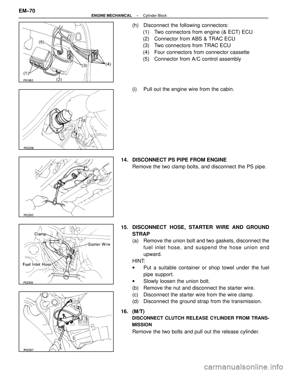
(h) Disconnect the following connectors:(1) Two connectors from engine (& ECT) ECU
(2) Connector from ABS & TRAC ECU
(3) Two connectors from TRAC ECU
(4) Four connectors from connector cassette
(5) Connector from A/C control assembly
(i) Pull out the engine wire from the cabin.
14. DISCONNECT PS PIPE FROM ENGINE Remove the two clamp bolts, and disconnect the PS pipe.
15. DISCONNECT HOSE, STARTER WIRE AND GROUND STRAP
(a) Remove the union bolt and two gaskets, disconnect thefuel inlet hose, and suspend the hose union end
upward.
HINT:
w Put a suitable container or shop towel under the fuel
pipe support.
w Slowly loosen the union bolt.
(b) Remove the nut and disconnect the starter wire.
(c) Disconnect the starter wire from the wire clamp.
(d) Disconnect the ground strap from the transmission.
16. (M/T)
DISCONNECT CLUTCH RELEASE CYLINDER FROM TRANS-
MISSION
Remove the two bolts and pull out the release cylinder.
EM±70
±
ENGINE MECHANICAL Cylinder Block
WhereEverybodyKnowsYourName