Page 1569 of 4087
2. CONNECT TRANSMISSION CONTROL ROD FROMSHIFT LEVER
Connect the control rod to the shift lever with the nut.
3. INSTALL PROPELLER SHAFT (See page PR±12)
4. INSTALL CENTER FLOOR CROSSMEMBER BRACE Install the crossmember brace with the 4 nuts.
Torque: 13 N Vm (130 kgf Vcm, 9 ft Vlbf)
5. INSTALL HEAT INSULATOR FOR FRONT EXHAUST PIPE
Install the heat insulator with the 4 bolts.
6. INSTALL CENTER EXHAUST PIPE Install the 2 hooks of the exhaust pipe to the rings on the ex-
haust pipe brackets.
±
1UZ±FE ENGINE ENGINE MECHANICALEG±193
WhereEverybodyKnowsYourName
Page 1570 of 4087

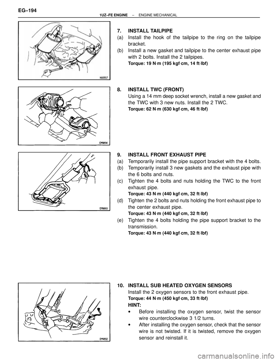
7. INSTALL TAILPIPE
(a) Install the hook of the tailpipe to the ring on the tailpipebracket.
(b) Install a new gasket and tailpipe to the center exhaust pipe with 2 bolts. Install the 2 tailpipes.
Torque: 19 N Vm (195 kgf Vcm, 14 ft Vlbf)
8. INSTALL TWC (FRONT)
Using a 14 mm deep socket wrench, install a new gasket and
the TWC with 3 new nuts. Install the 2 TWC.
Torque: 62 N Vm (630 kgf Vcm, 46 ft Vlbf)
9. INSTALL FRONT EXHAUST PIPE
(a) Temporarily install the pipe support bracket with the 4 bolts.
(b) Temporarily install 3 new gaskets and the exhaust pipe with
the 6 bolts and nuts.
(c) Tighten the 4 bolts and nuts holding the TWC to the front exhaust pipe.
Torque: 43 N Vm (440 kgf Vcm, 32 ft Vlbf)
(d) Tighten the 2 bolts and nuts holding the front exhaust pipe to
the center exhaust pipe.
Torque: 43 N Vm (440 kgf Vcm, 32 ft Vlbf)
(e) Tighten the 4 bolts holding the pipe support bracket to the
transmission.
Torque: 43 N Vm (440 kgf Vcm, 32 ft Vlbf)
10. INSTALL SUB HEATED OXYGEN SENSORS
Install the 2 oxygen sensors to the front exhaust pipe.
Torque: 44 N Vm (450 kgf Vcm, 33 ft Vlbf)
HINT:
w Before installing the oxygen sensor, twist the sensor
wire counterclockwise 3 1/2 turns.
w After installing the oxygen sensor, check that the sensor
wire is not twisted. If it is twisted, remove the oxygen
sensor and reinstall it.
EG±194
±
1UZ±FE ENGINE ENGINE MECHANICAL
WhereEverybodyKnowsYourName
Page 1574 of 4087
15. INSTALL POWER STEERING (PS) PUMP
(a) Install the PS pump with the nut and 3 bolts. Alternatelytighten the bolts and nut.
Torque:
39 NVm (400 kgf Vcm, 29 ft Vlbf) for bolt
43 N Vm (440 kgf Vcm, 32 ft Vlbf) for nut
16. INSTALL POWER STEERING (PS) RESERVOIR TANK
AND BRACKET
Install the reservoir tank and bracket assembly with the 3
bolts.
17. INSTALL POWER STEERING (PS) TUBES Install the PS tube clamp with the bolt.
18. INSTALL GENERATOR
(a) Install the generator and transmission oil cooler pipe bracket with the bolt and nut.
Torque: 37 N Vm (380 kgf Vcm, 27 ft Vlbf)
(b) Connect the generator connector.
(c) Connect the generator wire with the nut and cap.
19. INSTALL WIRE CLAMP (FOR GENERATOR) AND VSV
(FOR EVAP)
(a) Install the wire clamp to the VSV bracket.
(b) Install the VSV with the 2 bolts.
EG±198
±
1UZ±FE ENGINE ENGINE MEHANICAL
WhereEverybodyKnowsYourName
Page 1576 of 4087
(d) Install the upper radiator support with the 2 bolts and screw.Install the 2 upper radiator supports.
Torque: 12 N Vm (120 kgf Vcm, 9 ft Vlbf)
(e) Connect the following hoses:
(1) 2 oil cooler hoses (for cooling fan) to pipes
(2) 2 radiator hoses
(3) 2 oil cooler hoses (for transmission) to radiator
(4) Suction hose to hydraulic pump
(5) Pressure hose to hydraulic pump
EG±200
±
1UZ±FE ENGINE ENGINE MECHANICAL
WhereEverybodyKnowsYourName
Page 1578 of 4087
29. INSTALL AIR CLEANER
(a) Connect the air cleaner case to the air duct.
(b) Connect the air cleaner hose to the intake air connector.
(c) Install the air cleaner with the 3 bolts.
(d) Tighten the hose clamp bolt holding the air cleaner hose tothe intake air connector.
(e) Connect the VAF meter connector.
30. CONNECT CONTROL CABLES TO THROTTLE BODY
Connect the following cables:
(1) Accelerator cable
(2) Transmission throttle control cable
(3) Cruise control actuator cable
31. INSTALL THROTTLE BODY COVER
(a) Install the thro ttle body cover and hose clamp with the cap nut
and 2 bolts.
(b) Install the EVAP hose to the hose clamp.
32. INSTALL DRIVE BELT Install the drive belt by turning the drive belt tensioner coun-
terclockwise.
HINT: The pulley bolt for the dive belt tensioner has a left±
hand thread.
33. INSTALL BATTERY
EG±202
±
1UZ±FE ENGINE ENGINE MECHANICAL
WhereEverybodyKnowsYourName
Page 1579 of 4087
34. FILL WITH ENGINE COOLANT
35. FILL WITH ENGINE OIL
36. START ENGINE AND CHECK FOR LEAKS
37. CHECK TRANSMISSION FLUID LEVEL
38. PERFORM ENGINE ADJUSTMENT(See Tune±Up on pages EG±9 to 34)
39. INSTALL ENGINE UNDER COVER
40. INSTALL HOOD
41. PERFORM ROAD TEST Check for abnormal noise, shock slippage, correct shift
points and smooth operation.
42. RECHECK ENGINE COOLANT AND OIL LEVELS
±
1UZ±FE ENGINE ENGINE MECHANICALEG±203
WhereEverybodyKnowsYourName
Page 1581 of 4087
CYLINDER BLOCK
COMPONENTS FOR REMOVAL AND
INSTALLATION OF ENGINE WITH
TRANSMISSION
EM±116±
ENGINE MECHANICAL Cylinder Block
WhereEverybodyKnowsYourName
Page 1582 of 4087
COMPONENTS FOR REMOVAL AND
INSTALLATION OF ENGINE WITH
TRANSMISSION (Cont'd)
±
ENGINE MECHANICAL Cylinder BlockEM±117
WhereEverybodyKnowsYourName