Page 1008 of 4087

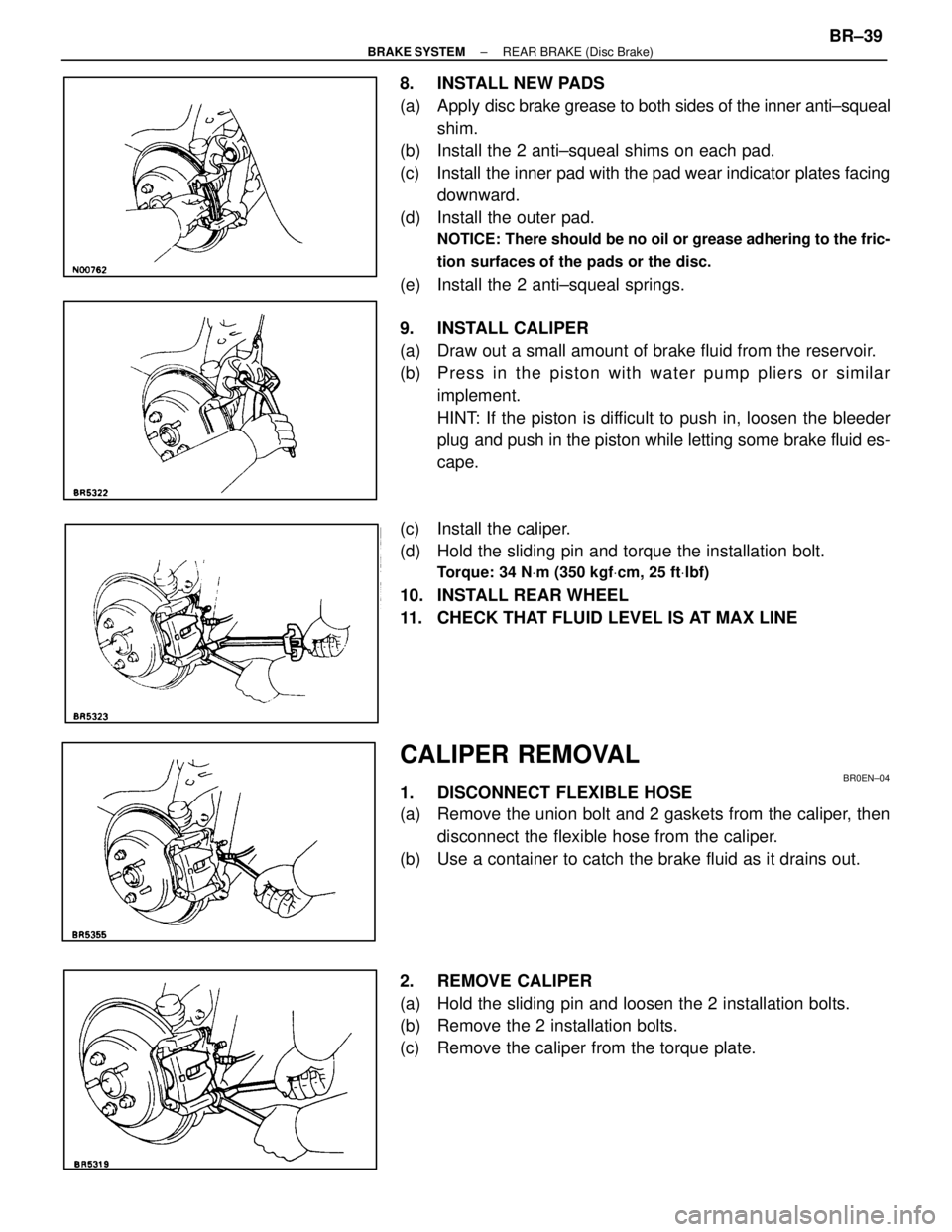
8. INSTALL NEW PADS
(a) Apply disc brake grease to both sides of the inner anti±squeal
shim.
(b) Install the 2 anti±squeal shims on each pad.
(c) Install the inner pad with the pad wear indicator plates facing
downward.
(d) Install the outer pad.
NOTICE: There should be no oil or grease adhering to the fric-
tion surfaces of the pads or the disc.
(e) Install the 2 anti±squeal springs.
9. INSTALL CALIPER
(a) Draw out a small amount of brake fluid from the reservoir.
(b) P re ss in th e pisto n with wa te r pu mp plie rs or simila r implement.
HINT: If the piston is difficult to push in, loosen the bleeder
plug and push in the piston while letting some brake fluid es-
cape.
(c) Install the caliper.
(d) Hold the sliding pin and torque the installation bolt.
Torque: 34 N Vm (350 kgf Vcm, 25 ft Vlbf)
10. INSTALL REAR WHEEL
11. CHECK THAT FLUID LEVEL IS AT MAX LINE
CALIPER REMOVAL
BR0EN±04
1. DISCONNECT FLEXIBLE HOSE
(a) Remove the union bolt and 2 gaskets from the caliper, then
disconnect the flexible hose from the caliper.
(b) Use a container to catch the brake fluid as it drains out.
2. REMOVE CALIPER
(a) Hold the sliding pin and loosen the 2 installation bolts.
(b) Remove the 2 installation bolts.
(c) Remove the caliper from the torque plate.
±
BRAKE SYSTEM REAR BRAKE (Disc Brake)BR±39
WhereEverybodyKnowsYourName
Page 1017 of 4087
2. APPLY HIGH TEMPERATURE GREASE TO ADJUSTER
3. CONNECT PARKING BRAKE CABLE TO PARKINGBRAKE LEVER
(a) Install the shoe hold±down springs, cups and pins.
(b) Connect the parking brake cable to the parking brake shoe
lever of the rear shoe.
4. INSTALL REAR SHOE Slide in the rear shoe between the shoe hold±down spring
cup and the backing plate.
NOTICE: Do not allow oil or grease to get on the rubbing face.
5. INSTALL TENSION SPRING, FRONT SHOE ANDADJUSTER
(a) Install the tension spring on the rear shoe.
(b) Install the front shoe on the tension spring.
(c) Install the adjuster between the front and rear shoes.
(d) Slide in the front shoe between the shoe hold±down spring
cup and the backing plate.
BR±48
±
BRAKE SYSTEM REAR BRAKE (Parking Brake)
WhereEverybodyKnowsYourName
Page 1081 of 4087
OKNG
OKNG
INSPECTION PROCEDURE
1Check ABS actuator solenoid.
C
OK
Hint
Hint
OK
C
Check continuity between terminal 4 and 1, 3, 4, 6 of the ABS actuator connector.
Continuity
Resistance of each solenoid coil is 1.2 �.
Check continuity between terminal 2 and 1, 4, 5, 6 of the ABS actuator connector.
Continuity
Resistance of each solenoid coil is 1.2 �.
Replace ABS actuator.
2Check for open and short in harness and connector between ABS (& TRAC) ECU \
and actuator
(See page IN±33).
Repair or replace harness or connector.
If the same code is still output after the diagnostic trouble code is dele\
ted, check the contact condition
of each connection.
If the connections are normal, the ECU may be defective.
BR±112±
BRAKE SYSTEM ANTI±LOCK BRAKE SYSTEM (ABS)
WhereEverybodyKnowsYourName
Page 1131 of 4087
SERVICE SPECIFICATIONS
SERVICE DATA
BatterySpecific gravity1.27±1.29
(when fully charged at 205C (68 5F))
AlternatorRated output12 V±100 A
Rotor coil resistance2.8±3.0 �
Slip ring diameterSTD 14.2±14.4 mm0.559±0567 in.
Limit 12.8 mm0.504 in.
Brush exposed lengthSTD 10.5 mm0.413 in.
Limit 1.5 mm0.059 in.
AlternatorRegulating voltageat 255C (77 5F)13.9±15.1 V
regulatorat 115 5C (239 5F)13.5±14.3 V
TORQUE SPECIFICATIONS
Part tightenedN Vmkgf Vcmft Vlbf
Alternator pulley X Rotor11 01,12581
Alternator X Alternator bracket37380 27
Alternator X Cylinder block3738027
±
CHARGING SYSTEM Service SpecificationsCH±21
WhereEverybodyKnowsYourName
Page 1142 of 4087
4. REMOVE ALTERNATOR(a) Disconnect the alternator connector.
(b) Remove the cap and nut, and disconnect the alternatorwire.
(c) Remove the bolt, and disconnect the A/T oil cooler pipe bracket.
(d) Remove the nut and alternator.
COMPONENTS FOR DISASSEMBLY AND
ASSEMBLY
DISASSEMBLY OF ALTERNATOR
1. REMOVE REAR END COVER (a) Remove the nut and terminal insulator.
CH±10
±
CHARGING SYSTEM Alternator
WhereEverybodyKnowsYourName
Page 1146 of 4087

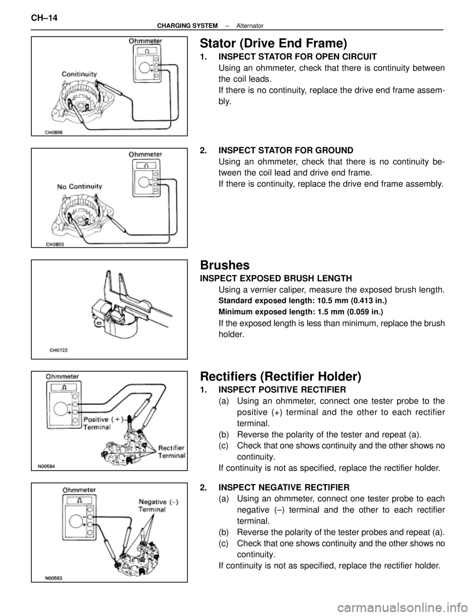
Stator (Drive End Frame)
1. INSPECT STATOR FOR OPEN CIRCUITUsing an ohmmeter, check that there is continuity between
the coil leads.
If there is no continuity, replace the drive end frame assem-
bly.
2. INSPECT STATOR FOR GROUND Using an ohmmeter, check that there is no continuity be-
tween the coil lead and drive end frame.
If there is continuity, replace the drive end frame assembly.
Brushes
INSPECT EXPOSED BRUSH LENGTHUsing a vernier caliper, measure the exposed brush length.
Standard exposed length: 10.5 mm (0.413 in.)
Minimum exposed length: 1.5 mm (0.059 in.)
If the exposed length is less than minimum, replace the brush
holder.
Rectifiers (Rectifier Holder)
1. INSPECT POSITIVE RECTIFIER(a) Using an ohmmeter, connect one tester probe to thepositive (+) terminal and the other to each rectifier
terminal.
(b) Reverse the polarity of the tester and repeat (a).
(c) Check that one shows continuity and the other shows no
continuity.
If continuity is not as specified, replace the rectifier holder.
2. INSPECT NEGATIVE RECTIFIER (a) Using an ohmmeter, connect one tester probe to each
negative (±) terminal and the other to each rectifier
terminal.
(b) Reverse the polarity of the tester probes and repeat (a).
(c) Check that one shows continuity and the other shows no
continuity.
If continuity is not as specified, replace the rectifier holder.
CH±14
±
CHARGING SYSTEM Alternator
WhereEverybodyKnowsYourName
Page 1152 of 4087
INSTALLATION OF ALTERNATOR
(See Components on page CH±9)
1. INSTALL ALTERNATOR (a) Install the alternator and A/T oil cooler bracket with the
bolt and nut.
Torque: 37 N Vm (380 kgf Vcm, 27 ft Vlbf)
(b) Connect the alternator connector.
(c) Connect the alternator wire with the nut and cap.
2. INSTALL DRIVE BELT Install the drive belt by turning the drive belt tensioner coun-
terclockwise.
HINT: The pulley bolt for the belt tensioner has a left±hand
thread.
3. CONNECT CABLE TO NEGATIVE TERMINAL OF BATTERY
4. PERFORM ON±VEHICLE INSPECTION (See steps 6 to 8 on pages CH±6 to 8)
5. INSTALL ENGINE UNDER COVER
CH±20
±
CHARGING SYSTEM Alternator
WhereEverybodyKnowsYourName
Page 1156 of 4087
LOCATION OF PLASTIC BODY PARTS
Outside Rear View Mirror (ABS)
Instrument Panel Safety Pad (PVC/PUR) Rear Spoiler (SMC)
Front Turn Signal Light (PC/PP)
Center Stop Light (PC)
Mead Light (PC/PP)
Head Light (PC/PP)
Front Bumper Extension
Mounting Bracket (PP)
Quarter Panel
Mud Guard (TPO)
Outside Moulding
Front Fender Mud Guard (TPO)
Front Spoiler (PUR) Cowl Top Ventilation Louver (PP)
Front Bumper Cover (PUR) Side Turn Signal Light (PMMA/ABS)
Cornering Light (PC)
HINT:
wResin material differs with model.
/ Made up of 2 or more kinds of materials.
PLASTIC BODY PARTSPP-4
WhereEverybodyKnowsYourName