Page 1168 of 4087
INSTALLATION
2. Temporarily install the front fender and thehood, and check the fit.
1. Temporarily install the new parts and mea-
sure each part in accordance with the body
dimension diagram.
NOTICE: Make sure each measurement is correct,
as this parts affects the front wheel alignment.
BODY PANEL REPLACEMENTRE-11
WhereEverybodyKnowsYourName
Page 1175 of 4087
INSTALLATION
Front Side
MemberFront Side Member
No. 3 Reinforcement
Front Side Member
Plate
1. Before temporarily installing the new front side member, weld the front side member
No. 3 reinforcement with standard points. 2. Temporarily install the new parts and measure
each part in accordance with the body dimen-
sion diagram.
NOTICE: Make sure each measurement is correct,
as this part affects the front wheel alignment.
BODY PANEL REPLACEMENTRE-18
WhereEverybodyKnowsYourName
Page 1248 of 4087

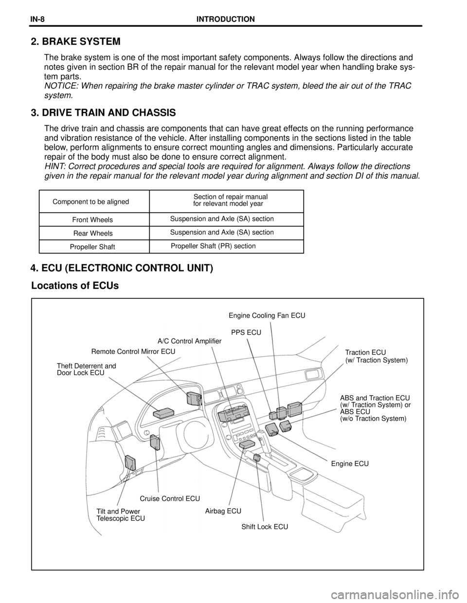
Shift Lock ECU
Tilt and Power
Telescopic ECU
Airbag ECU
Cruise Control ECU Engine ECUABS and Traction ECU
(w/ Traction System) or
ABS ECU
(w/o Traction System)
Theft Deterrent and
Door Lock ECU
(w/ Traction System)
Traction ECU
Remote Control Mirror ECU A/C Control Amplifier
PPS ECU
Engine Cooling Fan ECU
Component to be aligned
Section of repair manual
for relevant model year
Front Wheels Suspension and Axle (SA) section
Rear Wheels Suspension and Axle (SA) section
Propeller Shaft Propeller Shaft (PR) section
2. BRAKE SYSTEM
The brake system is one of the most important safety components. Always \
follow the directions and
notes given in section BR of the repair manual for the relevant model ye\
ar when handling brake sys-
tem parts.
NOTICE: When repairing the brake master cylinder or TRAC system, bleed t\
he air out of the TRAC
system.
3. DRIVE TRAIN AND CHASSIS
The drive train and chassis are components that can have great effects on the running performance
and vibration resistance of the vehicle. After installing components in \
the sections listed in the table
below, perform alignments to ensure correct mounting angles and dimensions. P\
articularly accurate
repair of the body must also be done to ensure correct alignment.
HINT: Correct procedures and special tools are required for alignment. Alway\
s follow the directionsgiven in the repair manual for the relevant model year during alignment \
and section DI of this manual.
4. ECU (ELECTRONIC CONTROL UNIT)
Locations of ECUs
INTRODUCTIONIN-8
WhereEverybodyKnowsYourName
Page 3013 of 4087
TROUBLESHOOTING FLOW±CHART
SR0GT±04
Trouble
�Hard steering at idle or low±speed driving.
� Steering too sensitive during high±speed driving.
Preliminary Check
�Check tire pressure.
� Check lubrication of suspension and steering linkage.
� Check front wheel alignment.
� Check steering system joint and suspension arm ball joint.
� Check for bent steering column.
� Check that all connectors are secure.
� Check PS pump fluid pressure. (See page SR±115)
SR±164±
STEERING POWER STEERING
WhereEverybodyKnowsYourName
Page 3238 of 4087
REAR SUSPENSION
SA0A4±07
DESCRIPTION
The suspension is double wishbone type at the rear. Optimal suspension geometry and wheel alignment
are achieved through analysis of the component design, materials and characteristics to provide a high
level of controllability and riding comfort.
The support rigidity of the suspension has been realized through the ado\
ption of the rear subframe.
±
SUSPENSION AND AXLE REAR SUSPENSIONSA±105
WhereEverybodyKnowsYourName
Page 3245 of 4087
3. INSTALL SHOCK ABSORBER TO REAR AXLE CARRIER
(a) Install the bolt from the rear vehicle.
(b) Temporarily install the nut.
4. INSTALL REAR BRAKE CALIPERInstall the brake caliper to the rear axle carrier with the 2 bolts.
Torque: 104 N Vm (1,065 kgf Vcm, 77 ft Vlbf)
5. STABILIZE SUSPENSION
(a) Install the rear wheel and lower vehicle
(b) Bounce the vehicle up and down several times to stabilize the
suspension.
(c) Jack up the vehicle and remove the rear wheel.
6. TIGHTEN BOLT AND NUT
(a) Support the lower arm with a jack.
(b) Tighten the bolt and nut.
Torque: 143 N Vm (1,460 kgf Vcm, 106 ft Vlbf)
7. INSTALL REAR WHEEL AND LOWER VEHICLE
Torqre: 137 N Vm (1,050 kgf Vcm, 101 ft Vlbf)
8. CHECK REAR WHEEL ALIGNMENT
(See page SA±10)
SA±112
±
SUSPENSION AND AXLE REAR SUSPENSION
WhereEverybodyKnowsYourName
Page 3256 of 4087
(d) Torque the nut on the body side of the No.1 lower suspension
arm.
Torque: 184 N Vm (1,880 kgf Vcm, 136 ft Vlbf)
HINT: Align the matchmarks on the adjusting cam and body.
(e) Torque the nut on the body side of the No.2 lower suspension
arm.
Torque: 184 N Vm (1,880 kgf Vcm, 136 ft Vlbf)
HINT: Align the matchmarks on the adjusting cam and body.
7. INSTALL REAR WHEEL AND LOWER VEHICLE
Torque: 103 N Vm (1,050 kgf Vcm, 76 ft Vlbf)
8. CHECK REAR WHEEL ALIGNMENT
(See page SA±10)
±
SUSPENSION AND AXLE REAR SUSPENSIONSA±123
WhereEverybodyKnowsYourName
Page 3268 of 4087

WHEEL ALIGNMENT
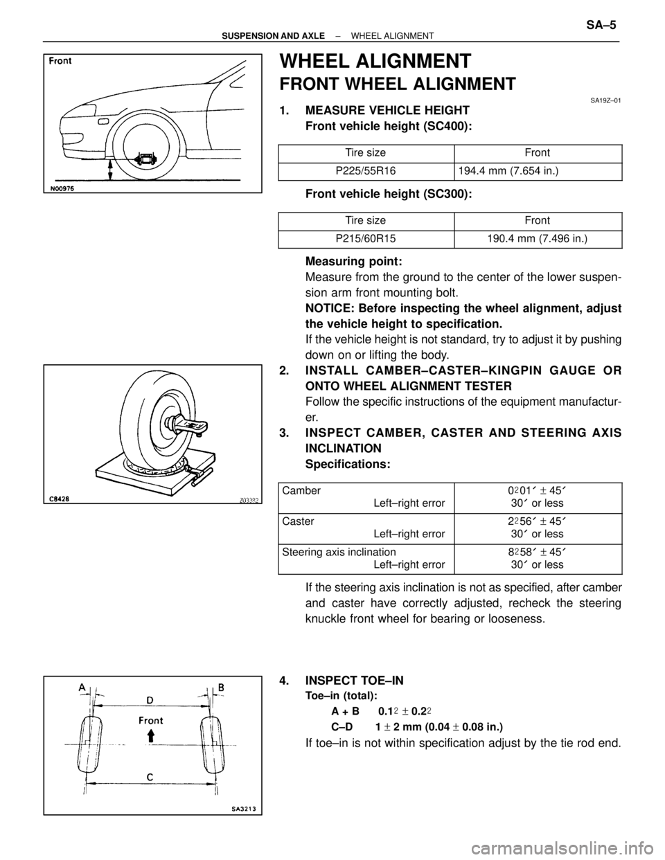
FRONT WHEEL ALIGNMENT
SA19Z±01
1. MEASURE VEHICLE HEIGHTFront vehicle height (SC400):
������������ ������������Tire size����������� �����������Front������������ ������������P225/55R16194.4 mm (7.654 in.)
Front vehicle height (SC300):
������������ ������������Tire size����������� �����������Front������������ ������������P215/60R15190.4 mm (7.496 in.)
Measuring point:
Measure from the ground to the center of the lower suspen-
sion arm front mounting bolt.
NOTICE: Before inspecting the wheel alignment, adjust
the vehicle height to specification.
If the vehicle height is not standard, try to adjust it by pushing
down on or lifting the body.
2. INSTALL CAMBER±CASTER±KINGPIN GAUGE OR ONTO WHEEL ALIGNMENT TESTER
Follow the specific instructions of the equipment manufactur-
er.
3. INSPECT CAMBER, CASTER AND STEERING AXIS INCLINATION
Specifications:
������������ �
�����������
������������Camber
Left±right error����������� �
����������
�����������0
�01 ' + 45 '
30 ' or less
������������ �
�����������
������������Caster
Left±right error2�56 ' + 45 '
30 ' or less
������������ �
�����������
������������
Steering axis inclination
Left±right error����������� �
����������
�����������
8
�58 ' + 45 '
30 ' or less
If the steering axis inclination is not as specified, after camber
and caster have correctly adjusted, recheck the steering
knuckle front wheel for bearing or looseness.
4. INSPECT TOE±IN
Toe±in (total): A + B 0.1 � + 0.2 �
C±D 1 + 2 mm (0.04 + 0.08 in.)
If toe±in is not within specification adjust by the tie rod end.
±
SUSPENSION AND AXLE WHEEL ALIGNMENTSA±5
WhereEverybodyKnowsYourName