Page 1267 of 4087
WATER PUMP
COMPONENTS FOR REMOVAL AND
INSTALLATION
REMOVAL OF WATER PUMP
1. REMOVE TIMING BELT(See steps 1 to 35 on pages EM±35 to 43)
2. REMOVE RH IGNITION COIL (a) Disconnect the ignition coil connector.
(b) Remove the two bolts and ignition coil.
3. REMOVE WATER INLET AND INLET HOUSING (a) Disconnect the water by±pass hose from the water inlethousing.
CO±8
±
COOLIING SYSTEM Water Pump
WhereEverybodyKnowsYourName
Page 1269 of 4087

INSTALLATION OF WATER PUMP
(See Components on page CO±8)
1. INSTALL WATER PUMP (a) Remove any old packing (FIPG) material and be careful
not to drop any oil on the contact surfaces of the water
pump and cylinder block.
w Using a razor blade and gasket scraper, remove all
the old packing (FIPG) material from the gasket
surfaces and sealing groove.
w Thoroughly clean all components to remove all the
loose material.
w Using a non±residue solvent, clean both sealing
surfaces.
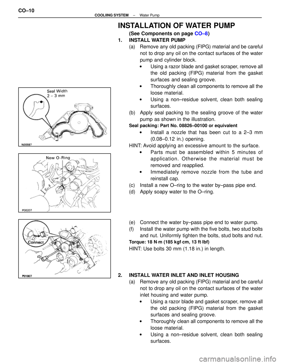
(b) Apply seal packing to the sealing groove of the water pump as shown in the illustration.
Seal packing: Part No. 08826±00100 or equivalent
w Install a nozzle that has been cut to a 2±3 mm
(0.08±0.12 in.) opening.
HINT: Avoid applying an excessive amount to the surface. w Parts must be assembled within 5 minutes of
application. Otherwise the material must be
removed and reapplied.
w Immediately remove nozzle from the tube and
reinstall cap.
(c) Install a new O±ring to the water by±pass pipe end.
(d) Apply soapy water to the O±ring.
(e) Connect the water by±pass pipe end to water pump.
(f) Install the water pump with the five bolts, two stud bolts and nut. Uniformly tighten the bolts, stud bolts and nut.
Torque: 18 N Vm (185 kgf Vcm, 13 ft Vlbf)
HINT: Use bolts 30 mm (1.18 in.) in length.
2. INSTALL WATER INLET AND INLET HOUSING (a) Remove any old packing (FIPG) material and be careful
not to drop any oil on the contact surfaces of the water
inlet housing and water pump.
w Using a razor blade and gasket scraper, remove all
the old packing (FIPG) material from the gasket
surfaces and sealing groove.
w Thoroughly clean all components to remove all the
loose material.
w Using a non±residue solvent, clean both sealing
surfaces.
CO±10
±
COOLIING SYSTEM Water Pump
WhereEverybodyKnowsYourName
Page 1270 of 4087

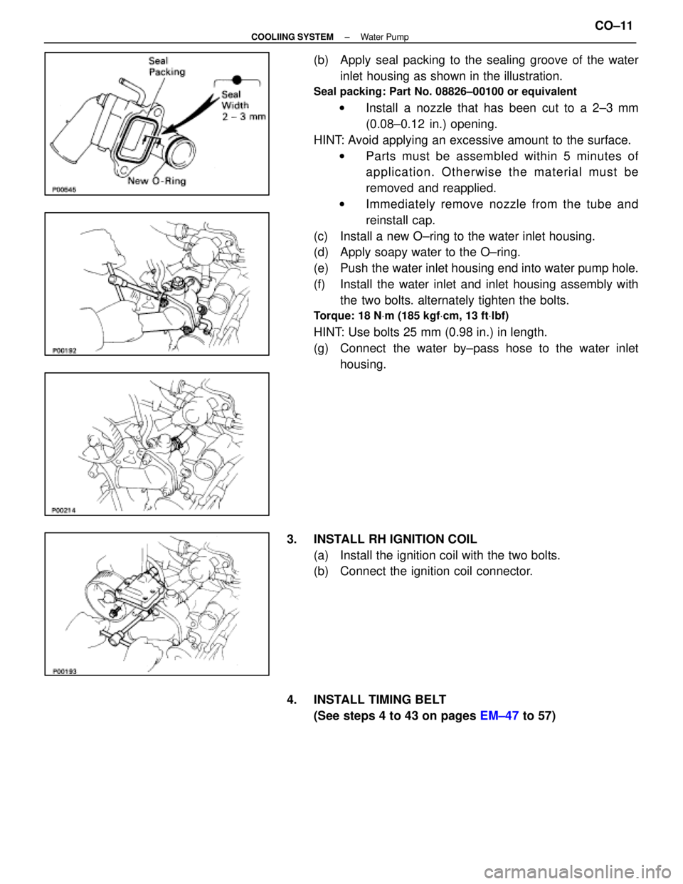
(b) Apply seal packing to the sealing groove of the waterinlet housing as shown in the illustration.
Seal packing: Part No. 08826±00100 or equivalent
w Install a nozzle that has been cut to a 2±3 mm
(0.08±0.12 in.) opening.
HINT: Avoid applying an excessive amount to the surface. w Parts must be assembled within 5 minutes of
application. Otherwise the material must be
removed and reapplied.
w Immediately remove nozzle from the tube and
reinstall cap.
(c) Install a new O±ring to the water inlet housing.
(d) Apply soapy water to the O±ring.
(e) Push the water inlet housing end into water pump hole.
(f) Install the water inlet and inlet housing assembly with the two bolts. alternately tighten the bolts.
Torque: 18 N Vm (185 kgf Vcm, 13 ft Vlbf)
HINT: Use bolts 25 mm (0.98 in.) in length.
(g) Connect the water by±pass hose to the water inlet
housing.
3. INSTALL RH IGNITION COIL (a) Install the ignition coil with the two bolts.
(b) Connect the ignition coil connector.
4. INSTALL TIMING BELT (See steps 4 to 43 on pages EM±47 to 57)
±
COOLIING SYSTEM Water PumpCO±11
WhereEverybodyKnowsYourName
Page 1277 of 4087
REMOVAL OF RADIATOR
(See Components on page CO±15)
1. REMOVE BATTERY CAUTION: Work must be started after approx. 20 seconds or
longer from the time the ignition switch is turned to the
ºLOCKº position and the negative (±) terminal cable is dis-
connected from the battery.
2. REMOVE ENGINE UNDER COVERS
3. DRAIN ENGINE COOLANT (See page CO±6)
4. REMOVE RADIATOR RESERVOIR TANK (a) Disconnect the coolant level sensor connector.
(b) Disconnect the following hoses:(1) Reservoir hose from water inlet housing
(2) Reservoir hose from radiator
(c) Remove the two bolts and reservoir tank bracket.
(d) Disconnect the reservoir tank from the reservoir tank bracket, and remove the reservoir tank.
5. DISCONNECT HOSES Disconnect the following hoses:(1) Upper radiator hose from radiator
(2) Lower radiator hose from radiator
(3) Two oil cooler hoses (for A/T) from radiator. Plug hose end.
CO±16
±
COOLIING SYSTEM Radiator
WhereEverybodyKnowsYourName
Page 1279 of 4087
(b) Slightly lift the radiator, and disconnect the two oil cooler
hoses (for cooling fan) from the hose clamp on the
radiator fan shrould.
(c) Remove the radiator.
(d) Remove the two lower radiator supports.
10. REMOVE FAN SHROULD FROM RADIATOR Remove the four bolts and fan shrould.
INSTALLATION OF RADIATOR
(See Components on page CO±15)
1. INSTALL FAN SHROULD TO RADIATOR Install the fan shrould with the four bolts.
Torque: 4.9 N Vm (50 kgf Vcm, 43 in. Vlbf)
2. INSTALL RADIATOR
(a) Install the two lower radiator supports to the radiator.
(b) Place the radiator on the body bracket.
(c) Slightly lift the radiator, and connect the two oil coolerhoses (for cooling fan) to the hose clamp on the radiator
fan shrould.
CO±18
±
COOLIING SYSTEM Radiator
WhereEverybodyKnowsYourName
Page 1281 of 4087
(3) Two oil cooler hoses (for A/T) to radiator.
(4) Lower radiator hose to radiator
(5) Upper radiator hose to radiator
7. INSTALL RADIATOR RESERVOIR TANK (a) Install the reservoir tank to the reservoir tank bracket.
(b) Install the reservoir tank bracket with two bolts.
Torque: 4.9 N Vm (50 kgf Vcm, 43 in. Vlbf)
(c) Connect the following hoses:
(1) Reservoir hose to water inlet housing
(2) Reservoir hose to radiator
(d) Connect the coolant level sensor connector.
8. INSTALL BATTERY
CO±20
±
COOLIING SYSTEM Radiator
WhereEverybodyKnowsYourName
Page 1283 of 4087

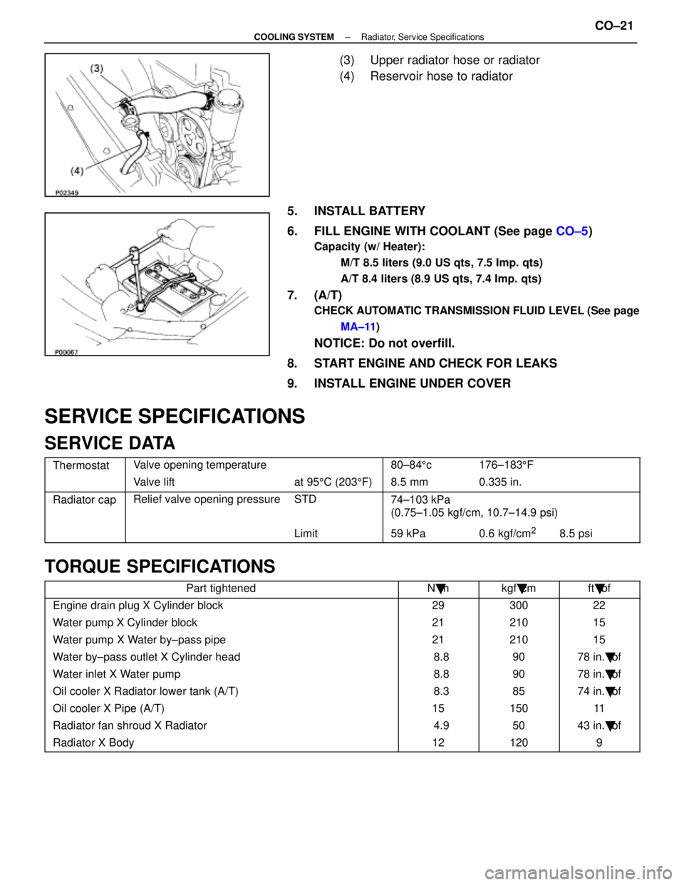
(3) Upper radiator hose or radiator
(4) Reservoir hose to radiator
5. INSTALL BATTERY
6. FILL ENGINE WITH COOLANT (See page CO±5)
Capacity (w/ Heater):
M/T 8.5 liters (9.0 US qts, 7.5 Imp. qts)
A/T 8.4 liters (8.9 US qts, 7.4 Imp. qts)
7. (A/T)
CHECK AUTOMATIC TRANSMISSION FLUID LEVEL (See pageMA±11 )
NOTICE: Do not overfill.
8. START ENGINE AND CHECK FOR LEAKS
9. INSTALL ENGINE UNDER COVER
SERVICE SPECIFICATIONS
SERVICE DATA
ThermostatValve opening temperature80±84 5c176±183 5F
Valve liftat 95 5C (203 5F) 8.5 mm0.335 in.
Radiator capRelief valve opening pressureSTD74±103 kPa
(0 75 1 05 k f/ 10 7 14 9 i)(0.75±1.05 kgf/cm, 10.7±14.9 psi)
Limit59 kPa0.6 kgf/cm28.5 psi
TORQUE SPECIFICATIONS
Part tightenedN �mkgf �cmft �lbf
Engine drain plug X Cylinder block2930022
Water pump X Cylinder block2121015
Water pump X Water by±pass pipe2121015
Water by±pass outlet X Cylinder head 8.89078 in. �lbf
Water inlet X Water pump 8.89078 in. �lbf
Oil cooler X Radiator lower tank (A/T) 8.38574 in. �lbf
Oil cooler X Pipe (A/T)1515011
Radiator fan shroud X Radiator 4.95043 in. �lbf
Radiator X Body121209
±
COOLING SYSTEM Radiator, Service SpecificationsCO±21
WhereEverybodyKnowsYourName
Page 1284 of 4087
ELECTRONICALLY CONTROLLED HYDRAULIC COOLING FAN
Description
In this way system, the cooling fan ECU controls the hydraulic pressure ac\
ting on the hydraulic motor, thus
controlling the speed of the cooling fan steplessly in response to the c\
ondition of the engine and air conditioner.
Operation
The hydraulic pump is driven by a drive belt (V±ribbed belt). The sole\
noid valve adjusts the volume of oil
sent from the hydraulic pump to the hydraulic motor which drives the fan dir\
ectly, thereby controlling the fan
speed. Oil which has passed through the hydraulic motor is cooled by the oil coole\
r before returning to the reservoir
tank. The solenoid valve is controlled by the computer in accordance with the E/G\
rpm, water temp. and A/C
signals. CO±22
±
COOLIING SYSTEM Electronically Controlled Hydraulic
Cooling Fan (Description, Operation)
WhereEverybodyKnowsYourName