Page 361 of 4087

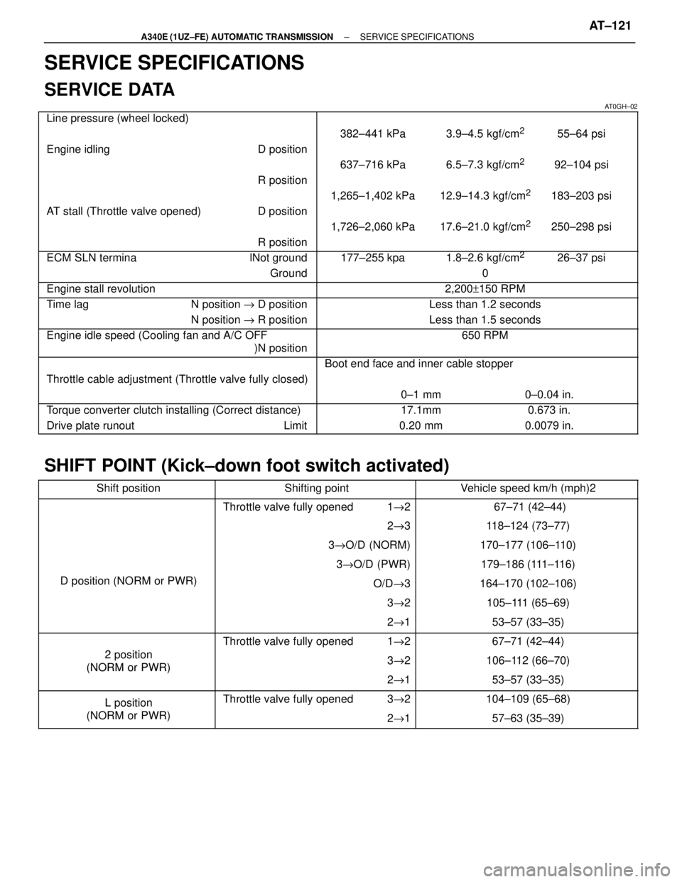
SERVICE SPECIFICATIONS
SERVICE DATA
AT0GH±02����������������� �����������������Line pressure (wheel locked)������������������\
�� ������������������\
��
����������������� �����������������������������������\
�� ������������������\
��382±441 kPa 3.9±4.5 kgf/cm255±64 psi
����������������� �����������������Engine idling D position������������������\
�� ������������������\
��
����������������� �����������������������������������\
�� ������������������\
��637±716 kPa 6.5±7.3 kgf/cm292±104 psi
����������������� �����������������R position������������������\
�� ������������������\
��
�����������������������������������\
��1,265±1,402 kPa 12.9±14.3 kgf/cm2183±203 psi����������������� �����������������AT stall (Throttle valve opened) D position������������������\
�� ������������������\
��
����������������� �����������������������������������\
�� ������������������\
��1,726±2,060 kPa 17.6±21.0 kgf/cm2250±298 psi����������������� �����������������R position������������������\
�� ������������������\
��
����������������� �����������������ECM SLN termina lNot ground������������������\
�� ������������������\
��177±255 kpa 1.8±2.6 kgf/cm226±37 psi
����������������� �����������������Ground������������������\
�� ������������������\
��0
����������������� �����������������Engine stall revolution������������������\
�� ������������������\
��2,200+150 RPM
����������������� �����������������Time lag N position " D position������������������\
�� ������������������\
��Less than 1.2 seconds
����������������� �����������������N position " R position������������������\
�� ������������������\
��Less than 1.5 seconds
����������������� �����������������Engine idle speed (Cooling fan and A/C OFF
)N position������������������\
�� ������������������\
��650 RPM
����������������� �����������������������������������\
�� ������������������\
��Boot end face and inner cable stopper����������������� �����������������Throttle cable adjustment (Throttle valve fully closed)������������������\
�� ������������������\
��
����������������� �����������������������������������\
�� ������������������\
��0±1 mm 0±0.04 in.
����������������� �����������������Torque converter clutch installing (Correct distance)������������������\
�� ������������������\
��17.1mm 0.673 in.
����������������� �����������������Drive plate runout Limit������������������\
�� ������������������\
��0.20 mm 0.0079 in.
SHIFT POINT (Kick±down foot switch activated)
����������� �����������Shift position������������� �������������Shifting point�������������� ��������������Vehicle speed km/h (mph)2
����������� ������������������������ �������������Throttle valve fully opened 1"2�������������� ��������������67±71 (42±44)
����������� ������������������������ �������������2" 3�������������� ��������������118±124 (73±77)
����������� ������������������������ �������������3" O/D (NORM)�������������� ��������������170±177 (106±110)
����������� ������������������������ �������������3" O/D (PWR)�������������� ��������������179±186 (111±116)
����������� �����������D position (NORM or PWR)������������� �������������O/D "3�������������� ��������������164±170 (102±106)
����������� ������������������������ �������������3" 2�������������� ��������������105±111 (65±69)����������� ������������������������ �������������2" 1�������������� ��������������53±57 (33±35)����������� �
����������
�����������2 iti
������������� �
������������
�������������Throttle valve fully opened 1
"2
�������������� �
�������������
��������������67±71 (42±44)
����������� �����������2 position
(NORM or PWR)������������� �������������3
" 2�������������� ��������������106±112 (66±70)
����������� �����������
(NORM or PWR)
������������� �������������2" 1�������������� ��������������53±57 (33±35)
����������� �����������L position������������� �������������Throttle valve fully opened 3 "2�������������� ��������������104±109 (65±68)
����������� �����������
L osition
(NORM or PWR)������������� �������������2" 1�������������� ��������������57±63 (35±39)
±
A340E (1UZ±FE) AUTOMATIC TRANSMISSION SERVICE SPECIFICATIONSAT±121
WhereEverybodyKnowsYourName
Page 538 of 4087

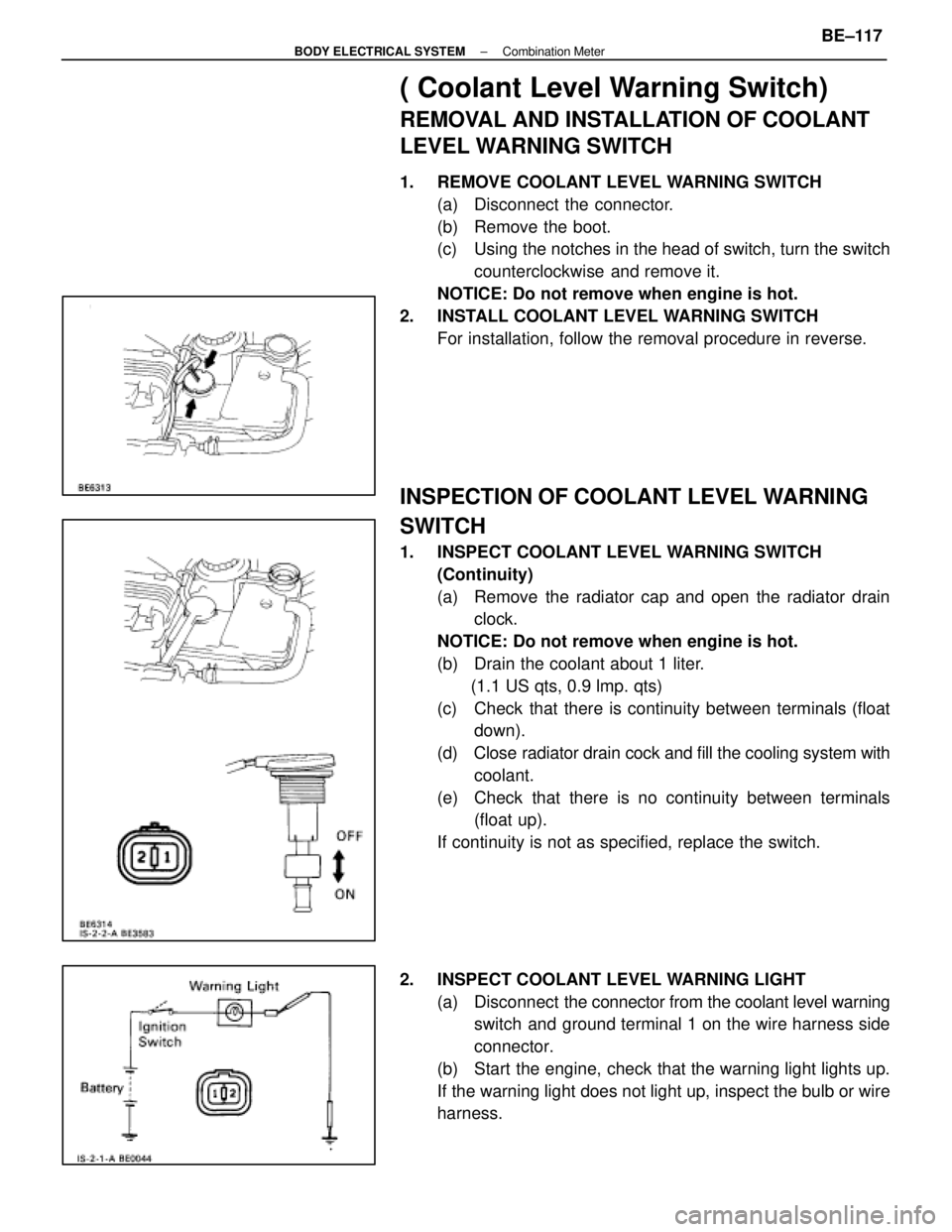
( Coolant Level Warning Switch)
REMOVAL AND INSTALLATION OF COOLANT
LEVEL WARNING SWITCH
1. REMOVE COOLANT LEVEL WARNING SWITCH(a) Disconnect the connector.
(b) Remove the boot.
(c) Using the notches in the head of switch, turn the switchcounterclockwise and remove it.
NOTICE: Do not remove when engine is hot.
2. INSTALL COOLANT LEVEL WARNING SWITCH For installation, follow the removal procedure in reverse.
INSPECTION OF COOLANT LEVEL WARNING
SWITCH
1. INSPECT COOLANT LEVEL WARNING SWITCH(Continuity)
(a) Remove the radiator cap and open the radiator drainclock.
NOTICE: Do not remove when engine is hot.
(b) Drain the coolant about 1 liter. (1.1 US qts, 0.9 lmp. qts)
(c) Check that there is continuity between terminals (float down).
(d) Close radiator drain cock and fill the cooling system with
coolant.
(e) Check that there is no continuity between terminals (float up).
If continuity is not as specified, replace the switch.
2. INSPECT COOLANT LEVEL WARNING LIGHT (a) Disconnect the connector from the coolant level warning
switch and ground terminal 1 on the wire harness side
connector.
(b) Start the engine, check that the warning light lights up.
If the warning light does not light up, inspect the bulb or wire
harness.
±
BODY ELECTRICAL SYSTEM Combination MeterBE±117
WhereEverybodyKnowsYourName
Page 840 of 4087
(c) Remove two screws and the ball set plate from theswitch body.
(b) Remove the ball and slide out the switch from the switch
body with the spring.
(d) Remove the boot.
9. REMOVE HEADLIGHT DIMMER SWITCH AND TURN SIGNAL SWITCH
Remove three screws and the switch from the switch body.
10. REMOVE WIPER AND WASHER SWITCH (a) Remove two screws and separate the bracket from theswitch body.
(b) Remove two screws and the switch from the switch body.
(c) Remove the boot.
BE±44
±
BODY ELECTRICAL SYSTEM Lighting System
WhereEverybodyKnowsYourName
Page 991 of 4087
COMPONENTS
BR03T±05
MASTER CYLINDER DISASSEMBLY
BR0EG±05
1. REMOVE MASTER CYLINDER BOOTUsing a screwdriver, remove the master cylinder boot.
2. REMOVE RESERVOIR CAP AND STRAINER
(a) Turn the reservoir cap the ªopenº side and remove it.
(b) Remove the strainer.
BR±14
±
BRAKE SYSTEM MASTER CYLINDER
WhereEverybodyKnowsYourName
Page 994 of 4087
8. INSTALL MASTER CYLINDER BOOTWith the UP mark on the master cylinder boot facing up-
wards, install the cylinder boot on the master cylinder.
MASTER CYLINDER INSTALLATION
BR0EJ±05
1. ADJUST LENGTH OF BRAKE BOOSTER PUSH RODBEFORE INSTALLING MASTER CYLINDER
(See page
BR±19)
2. INSTALL MASTER CYLINDER Install the master cylinder and a new gasket on the brake
booster with 3 nuts.
Torque: 13 N Vm (130 kgf Vcm, 9 ft Vlbf)
3. CONNECT BRAKE LINES
Using SST, connect the brake lines to the master cylinder.
Torque the union nuts.
SST 09023±00100
Torque: 12 N Vm (125 kgf Vcm, 9 ft Vlbf)
4. CONNECT LEVEL WARNING SWITCH CONNECTOR
5. FILL BRAKE R ESERVOIR WITH BRAKE FLUID AND
BLEED BRAKE SYSTEM
(See page BR±8)
6. w/ TRAC:
BLEED TRAC SYSTEM
(See page BR±10)
7. CHECK FOR FLUID LEAKAGE
8. CHECK AND ADJUST BRAKE PEDAL (See page BR±7 )
±
BRAKE SYSTEM MASTER CYLINDERBR±17
WhereEverybodyKnowsYourName
Page 1001 of 4087
2. REMOVE CALIPER
(a) Hold the sliding pin and loosen the 2 installation bolts.
(b) Remove the 2 installation bolts.
(c) Remove the caliper from the torque plate.
3. REMOVE FOLLOWING PARTS:
(a) 2 anti±squeal springs
(b) 2 brake pads
CALIPER DISASSEMBLY
BR043±0B
1. REMOVE CYLINDER BOOT SET RINGS AND CYLINDERBOOT
Using a screwdriver, remove the 2 cylinder boot set rings and
cylinder boots from the caliper.
2. REMOVE PISTONS
(a) Place a piece of cloth or similar article between the piston and
the caliper.
(b) Use compressed air to remove the pistons from the caliper.
CAUTION: Do not place your fingers in front of the piston when
using compressed air.
3. REMOVE PISTON SEALS Using a screwdriver, remove the piston seal from the caliper.
BR±32
±
BRAKE SYSTEM FRONT BRAKE (SC400)
WhereEverybodyKnowsYourName
Page 1002 of 4087
4. REMOVE SLIDING PINS AND DUST BOOTS
(a) Remove the 2 sliding pins from the torque plate.
(b) Using a screwdriver and hammer, tap out the 2 dust boots.
FRONT BRAKE COMPONENTS
INSPECTION AND REPAIR
BR044±08
1. MEASURE PAD LINING THICKNESSUsing a ruler, measure the pad lining thickness.
Standard thickness:
11.0 mm (0.433 in.)
Minimum thickness: 1.0 mm (0.039 in.)
Replace the pad if the pad's thickness is at the minimum
thickness or less, or if the pad has severely uneven wear.
2. MEASURE DISC THICKNESS Using a micrometer, measure the disc thickness.
Standard thickness:
32 mm (1.260 in.)
Minimum thickness: 30 mm (1.181 in.)
Replace the disc if the thickness of the disc is at the minimum
thickness or less. Replace the disc or grind it on a lathe if it
is scored or is worn unevenly.
±
BRAKE SYSTEM FRONT BRAKE (SC400)BR±33
WhereEverybodyKnowsYourName
Page 1004 of 4087
2. INSTALL DUST BOOTS AND SLIDING PINS
(a) Using a 19 mm socket and hammer, tap in 2 new dust bootsinto the torque plate.
(b) Confirm that the metal plate portion of the dust boot fits
snugly in the torque plate.
(c) Insert 2 sliding pins into the torque plate.
NOTICE: Insert the sliding pin with sliding bushing A into the
upper part, and insert the sliding pin with sliding bushing B
into the lower part.
3. INSTALL PISTON SEALS AND PISTONS IN CALIPER
4. INSTALL CYLINDER BOOTS AND CYLINDER BOOT SET RINGS
CALIPER INSTALLATION
BR046±0C
1. INSTALL FOLLOWING PARTS:
(a) 2 brake pads
(b) 2 anti±squeal springs
±
BRAKE SYSTEM FRONT BRAKE (SC400)BR±35
WhereEverybodyKnowsYourName