Page 2164 of 4087

(b) Check the brake drums for scoring or wear.
Maximum drum inside diameter:191 mm (7.520 in.)
(c) Clean the brake parts with a damp cloth.NOTICE: Do not use compressed air to clean the brake
parts.
(d) Seat the parking brake shoes during the road test (item 25) in do the following:
wDrive the vehicle at approx. 50 km/h (30 mph) on a safe,
level and dry road.
w With the parking brake release buttom pushed in, pull on
the lever with 88 N (9 kgf, 20 lbf) of force.
w Drive the vehicle for approx. 400 meters (1/4 mile) in this
condition.
w Repeat this procedure 2 or 3 times.
w Check parking pedal travel.
If necessary, adjust the parking brake.
16. INSPECT AND CHANGE BRAKE FLUID
(a) Visually inspect the master cylinder for leaks.
(b) Change brake fluid (See BR section)
Fluid: SAE J1703 or FMVSS No.116 DOT3
MA04F±01
CHASSIS
17. INSPECT STEERING LINKAGE
(a) Check the steering wheel freeplay.
Maximum freeplay:30 mm (1.18 in.)
With the vehicle stopped and pointed straight ahead, rock the
steering wheel gently back and forth with light finger pres-
sure.
(b) Check the steering linkage for looseness or damage. Check that:
wTie rod ends do not have excessive play.
w Dust seals and boots are not damaged.
w Boot clamps are not loose.
±
MAINTENANCE (1UZ ± FE)MA±13
WhereEverybodyKnowsYourName
Page 2181 of 4087
3. INSPECT FLEXIBLE COUPLING CENTERING BUSHINGwCheck for damage to the bushing.
If the bushing is damaged, replace the propeller shaft assem-
bly.
CENTER SUPPORT BEARING
REPLACEMENT
PR04K±01
1. SEPARATE INTERMEDIATE SHAFT AND PROPELLER SHAFT
(a) Place matchmarks on the intermediate shaft and propeller shaft.
(b) Separate the intermediate shaft and propeller shaft.
(c) Remove the dust boot from the propeller shaft.
HINT: If the dust boot is reused, remove it after wrapping vinyl
tape around the spline, so it will not be damaged.
2. REMOVE CENTER SUPPORT BEARING
(a) Using a snap ring expander, remove the snap ring.
(b) Using SST, remove the center bearing and dust deflector. SST 09950±20017
±
PROPELLER SHAFT PROPELLER SHAFTPR±9
WhereEverybodyKnowsYourName
Page 2183 of 4087
(d) Using a snap ring expander, install the new snap ring.
6. ASSEMBLE INTERMEDIATE SHAFT AND PROPELLERSHAFT
(a) Install the dust boot.
NOTICE: Assemble after wrapping vinyl tape around the
spline so it will not damage the boot.
(b) Apply grease to the spline.
Grease:
Molybdenum disulphide lithium base, NLGI No.2.
(c) Align the matchmarks and assemble the intermediate shaftand propeller shaft.
(d) Cover the adjusting nut with the dust boot.
NOTICE: The directions of the intermediate shaft com-
panion flange and the propeller shaft companion flange
should differ by 180 5.
(e) Tighten the adjusting nut fully by hand.
±
PROPELLER SHAFT PROPELLER SHAFTPR±11
WhereEverybodyKnowsYourName
Page 2230 of 4087
COMPRESSION CHECK
HINT: If there is lack of power, excessive oil consumption or
poor fuel economy, measure the compression pressure.
1. WARM UP AND STOP ENGINE Allow the engine to warm up to normal operating tempera-
ture.
2. REMOVE NO.3 TIMING BELT COVERS (See steps 1, 5 to 10 and 14 on pages EM±11 to 13)
3. DISCONNECT COLD START INJECTOR CONNECTOR
4. DISCONNECT RH CAM POSITION SENSOR CONNECTOR
(a) Disconnect the connector from the ignition coil bracket.
(b) Disconnect the sensor connector.
5. DISCONNECT LH CAM POSITION SENSOR CONNECTOR
6. REMOVE SPARK PLUGS (a) Disconnect the eight high±tension cords from the sparkplugs.
Disconnect the high±tension cords at rubber boot. Do
not pull on the cords.
NOTICE: Pulling on or bending the cords may damage
the conductor inside.
EM±30
±
ENGINE MECHANICAL Compression Check
WhereEverybodyKnowsYourName
Page 2241 of 4087

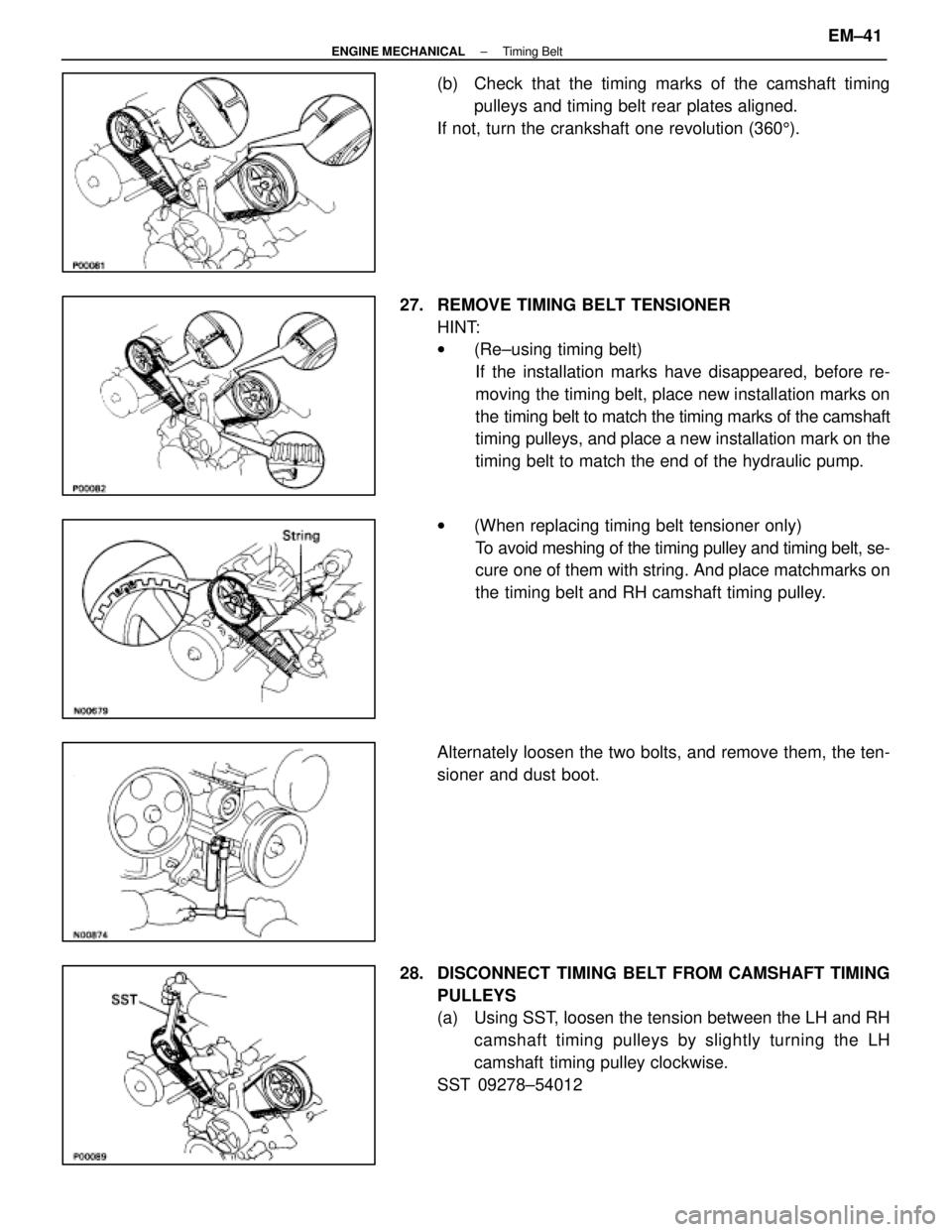
(b) Check that the timing marks of the camshaft timingpulleys and timing belt rear plates aligned.
If not, turn the crankshaft one revolution (360 5).
27. REMOVE TIMING BELT TENSIONER HINT:
w(Re±using timing belt)
If the installation marks have disappeared, before re-
moving the timing belt, place new installation marks on
the timing belt to match the timing marks of the camshaft
timing pulleys, and place a new installation mark on the
timing belt to match the end of the hydraulic pump.
w (When replacing timing belt tensioner only)
To avoid meshing of the timing pulley and timing belt, se-
cure one of them with string. And place matchmarks on
the timing belt and RH camshaft timing pulley.
Alternately loosen the two bolts, and remove them, the ten-
sioner and dust boot.
28. DISCONNECT TIMING BELT FROM CAMSHAFT TIMING PULLEYS
(a) Using SST, loosen the tension between the LH and RHcamshaft timing pulleys by slightly turning the LH
camshaft timing pulley clockwise.
SST 09278±54012
±
ENGINE MECHANICAL Timing BeltEM±41
WhereEverybodyKnowsYourName
Page 2250 of 4087

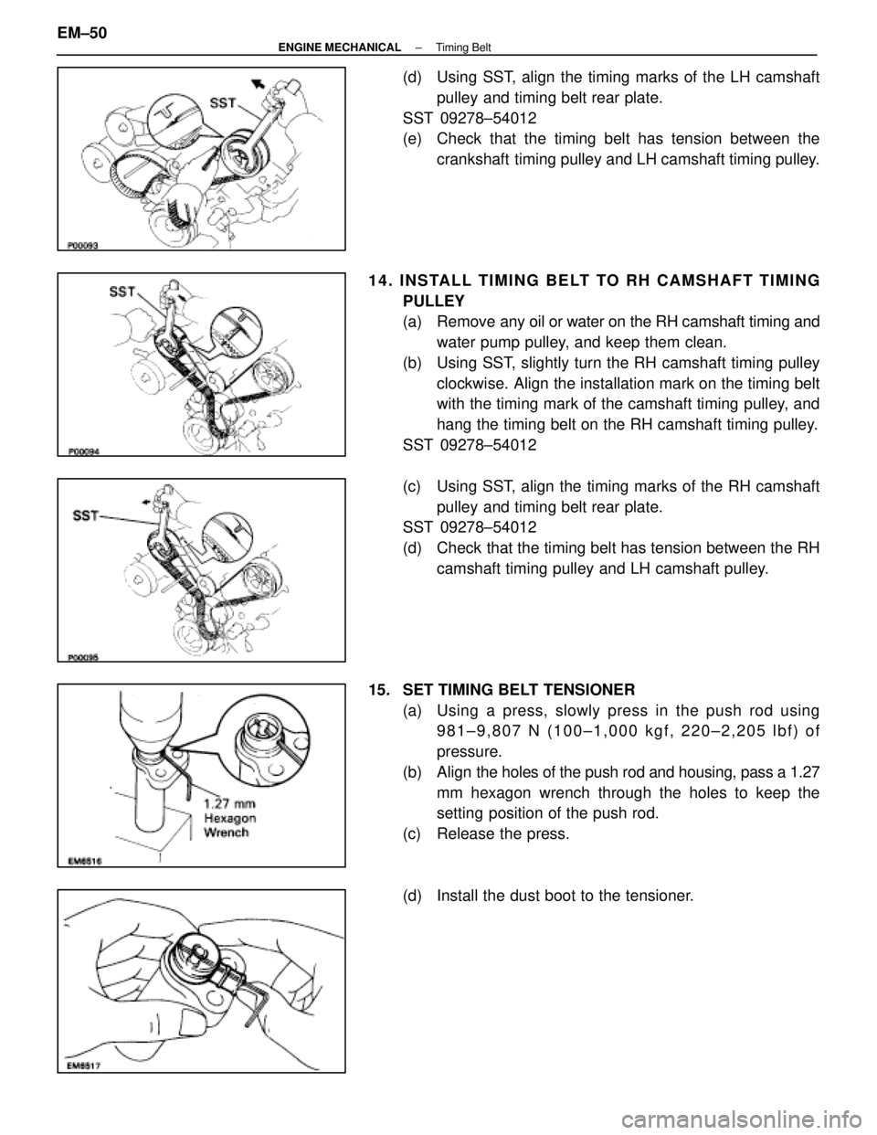
(d) Using SST, align the timing marks of the LH camshaftpulley and timing belt rear plate.
SST 09278±54012
(e) Check that the timing belt has tension between the crankshaft timing pulley and LH camshaft timing pulley.
14. INSTALL TIMING BELT TO RH CAMSHAFT TIMING PULLEY
(a) Remove any oil or water on the RH camshaft timing andwater pump pulley, and keep them clean.
(b) Using SST, slightly turn the RH camshaft timing pulley clockwise. Align the installation mark on the timing belt
with the timing mark of the camshaft timing pulley, and
hang the timing belt on the RH camshaft timing pulley.
SST 09278±54012
(c) Using SST, align the timing marks of the RH camshaft pulley and timing belt rear plate.
SST 09278±54012
(d) Check that the timing belt has tension between the RH
camshaft timing pulley and LH camshaft pulley.
15. SET TIMING BELT TENSIONER (a) Using a press, slowly press in the push rod using981±9,807 N (100±1,000 kgf, 220±2,205 lbf) of
pressure.
(b) Align the holes of the push rod and housing, pass a 1.27
mm hexagon wrench through the holes to keep the
setting position of the push rod.
(c) Release the press.
(d) Install the dust boot to the tensioner.
EM±50
±
ENGINE MECHANICAL Timing Belt
WhereEverybodyKnowsYourName
Page 2535 of 4087
6. REMOVE VSV FOR EVAP SYSTEMRemove the two bolts, and disconnect the VSV from cylinder
head and timing belt cover.
7. REMOVE RH NO.3 TIMING BELT COVER Remove the three bolts and timing belt cover.
8. REMOVE LH NO.3 TIMING BELT COVER (a) Remove the four mounting bolts.
(b) Disconnect the cord grommet from the timing belt cover,
and remove the timing belt cover.
(c) Remove the cord grommet from the high±tension cord.
9. REMOVE HIGH±TENSION CORDS (a) Disconnect the high±tension cords from the spark plugs
and distributor caps. Disconnect the high±tension cords
at the rubber boot. Do not pull on the cords.
NOTICE: Pulling on or bending the cords may damage
the conductor inside.
±
IGNITION SYSTEM High±Tension Cords and Cord ClampsIG±13
WhereEverybodyKnowsYourName
Page 2547 of 4087
7. DISCONNECT HIGH±TENSION CORDS FROMDISTRIBUTOR CAPS
Disconnect the high±tension cords at the rubber boot. Do not
pull on the cord.
NOTICE: Pulling or bending the cords may damage the
conductor inside.
8. REMOVE DISTRIBUTOR CAPS Loosen the three bolts, and remove the distributor cap. Re-
move the two distributor caps.
HINT: Arrange the distributor caps (RH side and LH side).
9. REMOVE DISTRIBUTOR ROTORS Loosen the two bolts, and remove the distributor rotor. Re-
move the two distributor rotors.
HINT: Arrange the distributor rotors (RH side and LH side).
10. REMOVE DISTRIBUTOR HOUSINGS (a) (RH Distributor Housing)Disconnect the cam position sensor connector.
(b) Re mo ve th e th re e bo lts an d distrib u to r ho u sin g . Remove the two distributor housings.
11. REMOVE CAM POSITION SENSORS FROM DISTRIBUTOR HOUSINGS
Remove the bolt, screw and cam position sensor.
Remove the two cam position sensors.
±
IGNITION SYSTEM DistributorIG±25
WhereEverybodyKnowsYourName