1991 LEXUS SC300 weight
[x] Cancel search: weightPage 1296 of 4087
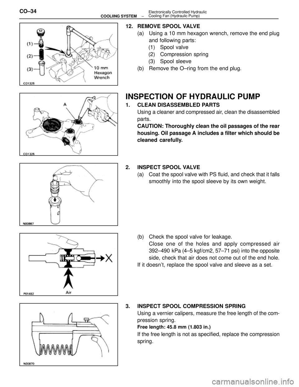
12. REMOVE SPOOL VALVE(a) Using a 10 mm hexagon wrench, remove the end plugand following parts:
(1) Spool valve
(2) Compression spring
(3) Spool sleeve
(b) Remove the O±ring from the end plug.
INSPECTION OF HYDRAULIC PUMP
1. CLEAN DISASSEMBLED PARTS Using a cleaner and compressed air, clean the disassembled
parts.
CAUTION: Thoroughly clean the oil passages of the rear
housing. Oil passage A includes a filter which should be
cleaned carefully.
2. INSPECT SPOOL VALVE (a) Coat the spool valve with PS fluid, and check that it falls
smoothly into the spool sleeve by its own weight.
(b) Check the spool valve for leakage. Close one of the holes and apply compressed air
392±490 kPa (4±5 kgf/cm2, 57±71 psi) into the opposite
side, check that air does not come out of the end hole.
If it doesn't, replace the spool valve and sleeve as a set.
3. INSPECT SPOOL COMPRESSION SPRING Using a vernier calipers, measure the free length of the com-
pression spring.
Free length: 45.8 mm (1.803 in.)
If the free length is not as specified, replace the compression
spring.
CO±34
±
COOLIING SYSTEM Electronically Controlled Hydraulic
Cooling Fan (Hydraulic Pump)
WhereEverybodyKnowsYourName
Page 1380 of 4087
The 1 UZ±FE engine has 8±cylinders in a V±arrangement at a bank an\
gle of 905. From the front of the RH
bank cylinders are numbered 2 ± 4 ± 6 ± 8, and from the front of t\
he LH bank cylinders are 1 ± 3 ± 5 ± 7.
The crankshaft is supported by 5 bearings inside the crankcase. These beari\
ngs are made of a copper and
lead alloy.
The crankshaft is integrated with 8 weights for balance. Oil holes are plac\
ed in the center of the crankshaft
to supply oil to the connecting rods, bearing, pistons and other component\
s.
The ignition order is 1 ± 8 ± 4 ± 3 ± 6 ± 5 ± 7 ± 2. T\
he cylinder head is made of alminum alloy, with a cross
flow type intake and exhaust layout and with pent±roof type combustion chambers. The spark plugs are
located in the center of the combustion chambers.
At the front and rear of the intake manifold, a water passage has been p\
rovided which connects the RH
and LH cylinder heads.
Exhaust and intake valves are equipped with irregular pitch springs made\
of special valve spring carbon
steel which are capable of functioning at all engine speeds.
The RH and LH intake camshaft are driven by a timing belt, and a gear on\
the intake camshaft engages
with a gear on the exhaust camshaft to drive it. The cam journal is supp\
orted at 5 (intake) or 4 (exhaust)
places between the valve lifters of each cylinder and on the front end o\
f the cylinder head. Lubrication of
the cam journals and gears is accomplished by oil being supplied through th\
e oiler port in the center of the
camshaft.
Adjustment of the valve clearance is done by means of an outer shim type\
system, in which valve adjusting
shims are located above the valve lifters. This permits replacement of the sh\
ims without removal of the
camshafts.
Pistons are made of high temperature±resistant aluminum alloy, and a depression is built into the piston
head to prevent interference with the valves.
Piston pins are the full±floating type, with the pins fastened to neither the piston boss nor the connecting
rods. Instead, snap rings are fitted on both ends of the pins, preventing the\
pins from falling out.
The No.1 compression ring is made of steel and the No.2 compression ring\
is made of cast iron. The oil
ring is made of a combination of steel and stainless steel. The outer diamet\
er of each piston ring is slightly
larger than the diameter of the piston and the flexibility of the rings allows them to hug the cylinder walls
when they are mounted on the piston. Compression rings No.1 and No.2 work to\
prevent gas leakage from
the cylinder and the oil ring works to scrape oil off the cylinder walls to prevent it from entering the combus-
tion chambers.
The cylinder block is made of aluminum alloy with a bank of 90 5. Cast iron cylinders are installed inside
the cylinder block. It has 8 cylinders which are approximately twice the le\
ngth of the piston stroke. The top
of each cylinder is closed off by the cylinder head and the lower end of the cylinders becomes the crank-
case, in which the crankshaft is installed. In addition, the cylinder block c\
ontains a water jacket, through
which coolant is pumped to cool the cylinders.
The No.1 and No.2 oil pans are bolted onto the bottom of the cylinder bl\
ock. The No.1 oil pan is made of
aluminum alloy. The No.2 oil pan is an oil reservoir made of pressed steel sheet. An o\
il level sensor is
installed in the No.1 oil pan (If oil level drops below a set level, a warning light\
s up.). And oil pan baffle plate
keeps sufficient oil in the bottom of the No.2 oil pan even when the vehicle is t\
ilted. This dividing plate also
prevents the oil from marking waves when the vehicle is stopped suddenly\
and the oil shifts away from the
oil pump suction pipe.
Plastic region tighten bolts are used for the cylinder head, main bearin\
g cap and connecting rod.
EG±4
±
1UZ±FE ENGINE ENGINE MECHANICAL
WhereEverybodyKnowsYourName
Page 1556 of 4087
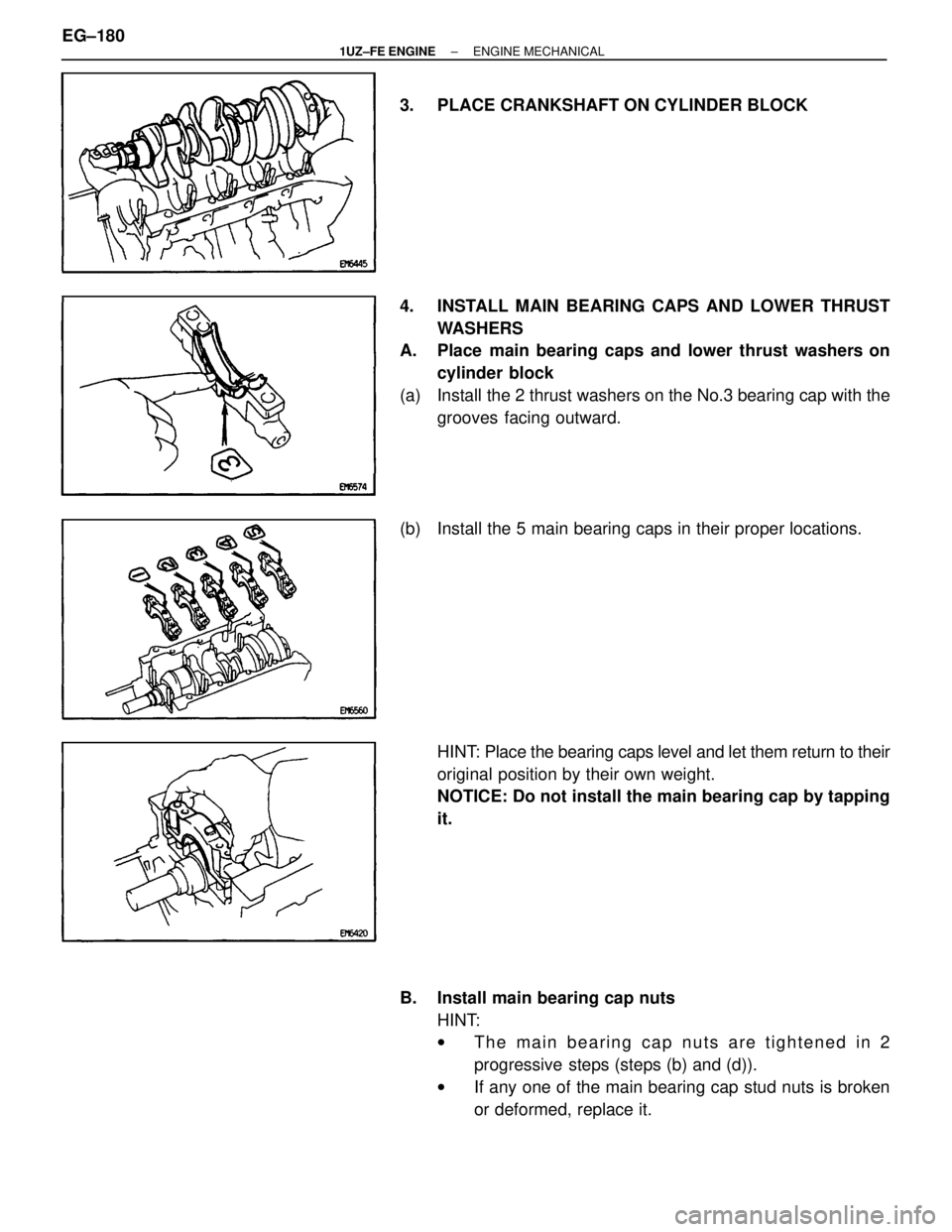
3. PLACE CRANKSHAFT ON CYLINDER BLOCK
4. INSTALL MAIN BEARING CAPS AND LOWER THRUSTWASHERS
A. Place main bearing caps and lower thrust washers on
cylinder block
(a) Install the 2 thrust washers on the No.3 bearing cap with the grooves facing outward.
(b) Install the 5 main bearing caps in their proper locations.
HINT: Place the bearing caps level and let them return to their
original position by their own weight.
NOTICE: Do not install the main bearing cap by tapping
it.
B. Install main bearing cap nuts HINT:
wThe main bearing cap nuts are tightened in 2
progressive steps (steps (b) and (d)).
w If any one of the main bearing cap stud nuts is broken
or deformed, replace it.
EG±180
±
1UZ±FE ENGINE ENGINE MECHANICAL
WhereEverybodyKnowsYourName
Page 1622 of 4087
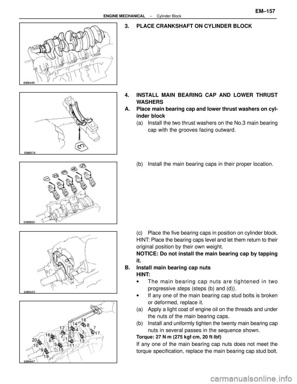
3. PLACE CRANKSHAFT ON CYLINDER BLOCK
4. INSTALL MAIN BEARING CAP AND LOWER THRUSTWASHERS
A. Place main bearing cap and lower thrust washers on cyl-
inder block
(a) Install the two thrust washers on the No.3 main bearing cap with the grooves facing outward.
(b) Install the main bearing caps in their proper location.
(c) Place the five bearing caps in position on cylinder block.
HINT: Place the bearing caps level and let them return to their
original position by their own weight.
NOTICE: Do not install the main bearing cap by tapping
it.
B. Install main bearing cap nuts HINT:
wThe main bearing cap nuts are tightened in two
progressive steps (steps (b) and (d)).
w If any one of the main bearing cap stud bolts is broken
or deformed, replace it.
(a) Apply a light coat of engine oil on the threads and under
the nuts of the main bearing caps.
(b) Install and uniformly tighten the twenty main bearing cap
nuts in several passes in the sequence shown.
Torque: 27 N Vm (275 kgf Vcm, 20 ft Vlbf)
If any one of the main bearing cap nuts does not meet the
torque specification, replace the main bearing cap stud bolt.
±
ENGINE MECHANICAL Cylinder BlockEM±157
WhereEverybodyKnowsYourName
Page 1647 of 4087
The 1 UZ±FE engine has 8±cylinders in a V±arrangement at a bank an\
gle of 905. From the front of the RH
bank cylinders are numbered 2±4±6±8, and from the front of the LH b\
ank cylinders are numbered 1 ±3±5±7.
The crankshaft is supported by 5 bearings specified by the inside of the cr\
ankcase. These bearings are made
of a copper and lead alloy. The crankshaft is integrated with 8 weights which are cast along with it\
for balancing. Oil holes are built
into the center of the crankshaft for supplying oil to the connecting ro\
ds, pistons and other components. The ignition order is 1±8±4±3±6±5±7±2. The cylinder\
head is made of aluminum alloy, with a cross flow
type intake and exhaust layout and with pent±roof type combustion chambers. The spark plugs are loca\
ted in
the center of the combustion chambers.
At the front and rear of the intake manifold, a water passage has been p\
rovided which connects the RH
and LH cylinder heads. Exhaust and intake valves are equipped with irregular pitch springs made\
of special valve spring carbon
steel which are capable of following no matter what the engine speed.
The RH and LH intake camshafts are driven by a single timing belt, and a ge\
ar on the intake camshaft en-
gages with a gear on the exhaust camshaft to drive it. The camshaft jour\
nal is supported at 5 (intake) or 4 (ex-
haust) places between the valve lifters of each cylinder and on the front end of the cylinder \
head. Lubrication
of the cam journal gear is accomplished by oil being supplied through the \
oiler port in the center of the camshaft. Adjustment of the valve clearance is done by means of an outer shim type\
system, in which valve adjusting
shims are located above the valve lifters. This permits replacement of the sh\
ims without removal of the cam-
shafts. Pistons are made of high temperature±resistant aluminum alloy, and a depression is built into the piston
head to prevent interference with valves.
Piston pins are the full±floating type, with the pins fastened to neither the piston boss nor the connecting
rods. Instead, snap rings are fitted on both ends of the pins, preventing the\
pins from falling out. The No.1 compression ring is made of steel and the No.2 compression ring\
is made of cast iron. The oil
ring is m ade of a combination of steel and stainless steel. The outer diameter of\
each piston ring is slightly larger
than the diameter of the piston and the flexibility of the rings allows them\
to hug the cylinder walls when they
are mounted on the piston. Compression rings No.1 and No.2 work to prevent \
the leakage of gas from the cylin-
der and the oil ring works to scrape oil off the cylinder walls to prevent it from entering the combustion chamber. The cylinder block is made of aluminum alloy with a bank angle of 90 5. Cast iron cylinders are installed
inside the cylinder block. It has 8 cylinders which are approximately twice the length of th\
e piston stroke. The
top of each cylinder is closed off by the cylinder heads and the lower end of the cylinders becomes the crank-
case, in which the crankshaft is installed. In addition, the cylinder bl\
ock contains a water jacket, through which
coolant is pumped to cool the cylinders. The No.1 and No.2 oil pans are bolted onto the bottom of the cylinder block\
. The No.1 oil pan is made of
aluminum alloy. The No.2 oil pan is an oil reservoir made of pressed steel sheet. An o\
il level sensor is installed
in the No.1 oil pan (If the oil level drops below a set level, a warnin\
g light lights up.). A oil pan baffle plate keeps
sufficient oil in the bottom of the No.2 oil pan even when the vehicle is tilted. \
This dividing plate also prevents
the oil from making waves when the vehicle is stopped suddenly and the oil \
shifts away from the oil pump suction
pipe. Plastic region tightening bolts are used for the cylinder head, main bearing ca\
p and connecting rod.
EM±4
±
ENGINE MECHANICAL Operation
WhereEverybodyKnowsYourName
Page 2134 of 4087
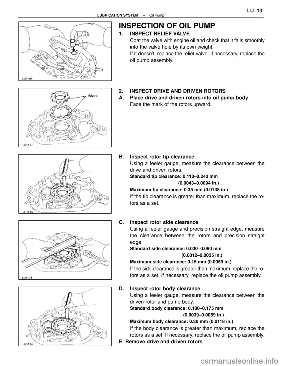
INSPECTION OF OIL PUMP
1. INSPECT RELIEF VALVECoat the valve with engine oil and check that it falls smoothly
into the valve hole by its own weight.
If it doesn't, replace the relief valve. If necessary, replace the
oil pump assembly.
2. INSPECT DRIVE AND DRIVEN ROTORS
A. Place drive and driven rotors into oil pump body Face the mark of the rotors upward.
B. Inspect rotor tip clearance Using a feeler gauge, measure the clearance between the
drive and driven rotors.
Standard tip clearance: 0.110±0.240 mm
(0.0043±0.0094 in.)
Maximum tip clearance: 0.35 mm (0.0138 in.)
If the tip clearance is greater than maximum, replace the ro-
tors as a set.
C. Inspect rotor side clearance Using a feeler gauge and precision straight edge, measure
the clearance between the rotors and precision straight
edge.
Standard side clearance: 0.030±0.090 mm
(0.0012±0.0035 in.)
Maximum side clearance: 0.15 mm (0.0059 in.)
If the side clearance is greater than maximum, replace the ro-
tors as a set. If necessary, replace the oil pump assembly.
D. Inspect rotor body clearance Using a feeler gauge, measure the clearance between the
driven rotor and pump body.
Standard body clearance: 0.100±0.175 mm
(0.0039±0.0069 in.)
Maximum body clearance: 0.30 mm (0.0118 in.)
If the body clearance is greater than maximum, replace the
rotors as a set. If necessary, replace the oil pump assembly.
E. Remove drive and driven rotors
±
LUBRICATION SYSTEM Oil PumpLU±13
WhereEverybodyKnowsYourName
Page 2145 of 4087
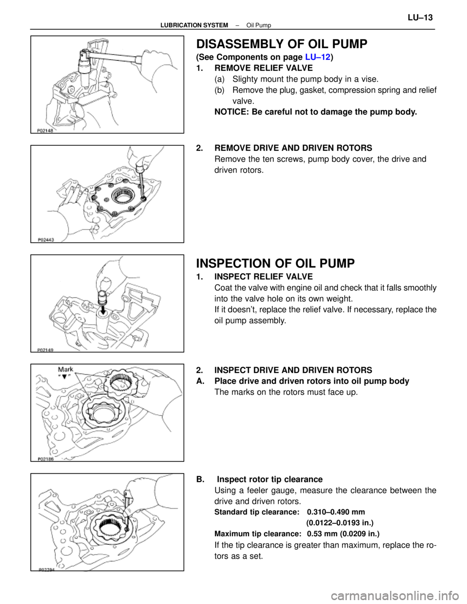
DISASSEMBLY OF OIL PUMP
(See Components on page LU±12)
1. REMOVE RELIEF VALVE (a) Slighty mount the pump body in a vise.
(b) Remove the plug, gasket, compression spring and reliefvalve.
NOTICE: Be careful not to damage the pump body.
2. REMOVE DRIVE AND DRIVEN ROTORS Remove the ten screws, pump body cover, the drive and
driven rotors.
INSPECTION OF OIL PUMP
1. INSPECT RELIEF VALVECoat the valve with engine oil and check that it falls smoothly
into the valve hole on its own weight.
If it doesn't, replace the relief valve. If necessary, replace the
oil pump assembly.
2. INSPECT DRIVE AND DRIVEN ROTORS
A. Place drive and driven rotors into oil pump body The marks on the rotors must face up.
B. Inspect rotor tip clearance Using a feeler gauge, measure the clearance between the
drive and driven rotors.
Standard tip clearance: 0.310±0.490 mm
(0.0122±0.0193 in.)
Maximum tip clearance: 0.53 mm (0.0209 in.)
If the tip clearance is greater than maximum, replace the ro-
tors as a set.
±
LUBRICATION SYSTEM Oil PumpLU±13
WhereEverybodyKnowsYourName
Page 2357 of 4087
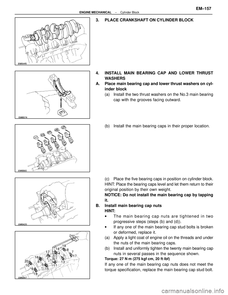
3. PLACE CRANKSHAFT ON CYLINDER BLOCK
4. INSTALL MAIN BEARING CAP AND LOWER THRUSTWASHERS
A. Place main bearing cap and lower thrust washers on cyl-
inder block
(a) Install the two thrust washers on the No.3 main bearing cap with the grooves facing outward.
(b) Install the main bearing caps in their proper location.
(c) Place the five bearing caps in position on cylinder block.
HINT: Place the bearing caps level and let them return to their
original position by their own weight.
NOTICE: Do not install the main bearing cap by tapping
it.
B. Install main bearing cap nuts HINT:
wThe main bearing cap nuts are tightened in two
progressive steps (steps (b) and (d)).
w If any one of the main bearing cap stud bolts is broken
or deformed, replace it.
(a) Apply a light coat of engine oil on the threads and under
the nuts of the main bearing caps.
(b) Install and uniformly tighten the twenty main bearing cap
nuts in several passes in the sequence shown.
Torque: 27 N Vm (275 kgf Vcm, 20 ft Vlbf)
If any one of the main bearing cap nuts does not meet the
torque specification, replace the main bearing cap stud bolt.
±
ENGINE MECHANICAL Cylinder BlockEM±157
WhereEverybodyKnowsYourName