Page 15 of 4087

PRECAUTIONS FOR VEHICLES
EQUIPPED WITH A CATALYTIC
CONVERTER
CAUTION: If large amounts of unburned gasoline flow into the
converter, it may overheat and create a fire hazard. To prevent
this, observe the following precautions and explain them to
your customer.
1. Use only unleaded gasoline.
2. Avoid prolonged idling. Avoid running the engine at idle speed for more than 20 min-
utes.
3. Avoid spark jump test. (a) P e r f o r m s p a r k j u m p t e s t o n l y w h e n a b s o l u t e l ynecessary. Perform this test as rapidly as possible.
(b) While testing, never race the engine.
4. Avoid prolonged engine compression measurement.
Engine compression tests must be done as rapidly as pos-
sible.
5. Do not run engine when fuel tank is nearly empty. This may c ause the engine to misfire and create an extra load
on the converter.
6. Avoid coasting with ignition turned off and prolonged braking.
7. Do not dispose of used catalyst along with parts contaminated with gasoline or oil.
IN±12
±
INTRODUCTION Precautions for Vehicles Equipped with a Catalytic
Converter
WhereEverybodyKnowsYourName
Page 380 of 4087

NO.2 VEHICLE SPEED SENSOR
REPLACEMENT
AT0GF±02
1. DISCONNECT NO.2 VEHICLE SPEED SENSORCONNECTOR
2. REMOVE NO.2 VEHICLE SPEED SENSOR
(a) Remove the bolt and No.2 vehicle speed sensor.
(b) Remove the O±ring from it.
3. INSPECT NO.2 VEHICLE SPEED SENSOR (See page AT±86)
4. INSTALL NO.2 VEHICLE SPEED SENSOR
(a) Cost a new O±ring with ATF and install it to the speed sensor.
(b) Install the speed sensor and torque the bolt.
Torque: 5.4 N Vm (55 kgf Vcm, 48 in. Vlbf)
5. CONNECT NO.2 VEHICLE SPEED SENSOR
CONNECTOR
O/D DIRECT CLUTCH SPEED SENSOR
REPLACEMENT
AT072±04
1. REMOVE FRONT EXHAUST PIPE AND LH SIDECATALYTIC CONVERTER
(See pages EG±204)
2. REMOVE LH SIDE HEAT INSULATORS
3. DISCONNECT O / D DIRECT CLUTCH SPEED SENSOR CONNECTOR
4. REMOVE O/D DIRECT CLUTCH SPEED SENSOR
(a) Remove the bolt and O/D direct clutch speed sensor.
(b) Remove the O±ring from it.
5. INSPECT O/D DIRECT CLUTCH SPEED SENSOR (See page AT±98)
6. INSTALL O/D DIRECT CLUTCH SPEED SENSOR
(a) Coat a new O±ring with ATF and install it to the O/D direct clutch speed sensor.
(b) Install the O/D direct clutch speed sensor and torque the bolt.
Torque: 5.4 N Vm (55 kgf Vcm, 48 in. Vlbf)
7. CONNECT O/D DIRECT CLUTCH SPEED SENSOR
CONNECTOR
8. INSTALL LH SIDE HEAT INSULATORS
9. INSTALL LH SIDE CATALYTIC CONVERTER AND FRONT EXHAUST PIPE
(See page EG±204)
±
A304E (1UZ±FE) AUTOMATIC TRANSMISSION SPEED SENSORAT±17
WhereEverybodyKnowsYourName
Page 1326 of 4087
SERVICE SPECIFICATIONS
SPECIFICATIONS
VSV (For EVAP) Resistance30±34 �
VSV (For EGR)Resistance33±39 �
TORQUE SPECIFICATIONS
Part tightenedN mkgf cmftVlbf
VSV for EGR X Intake manifold18185 13
EGR valve X Intake manifold18185 13
EGR valve X EGR Pipe64650 47
Catalytic converter (Front) X Exhaust manifold62630 46
Catalytic converter (Front) X Front Exhaust pipe43440 32
Front exhaust pipe X Center exhaust pipe43440 32
Sub±oxygen sensor X Front exhaust pipe1818013
EC±20±
EMISSION CONTROL SYSTEMS Service Specifications
WhereEverybodyKnowsYourName
Page 1328 of 4087
INSPECTION OF EXHAUST PIPE
ASSEMBLY
1. CHECK CONNECTIONS FOR LOOSENESS OR DAMAGE
2. CHECK CLAMPS FOR WEAKNESS, CRACKS OR
DAMAGE
INSPECTION OF CATALYTIC
CONVERTERS
CHECK FOR DENTS OR DAMAGE If any part of protector is damaged or dented to the extent that
it contacts the converter, repair or replace it.
INSPECTION OF HEAT INSULATORS
1. CHECK HEAT INSULATOR FOR DAMAGE
2. CHECK FOR ADEQUATE CLEARANCE BETWEEN
CATALYTIC CONVERTER AND HEAT INSULATOR
COMPONENTS FOR REPLACEMENT OF CATALYTIC CONVERTERS
±
EMISSION CONTROL SYSTEMS Three±Way Catalyst (TWC) SystemEC±27
WhereEverybodyKnowsYourName
Page 1329 of 4087

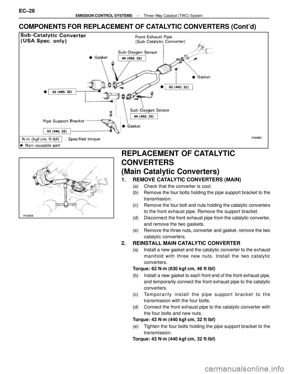
COMPONENTS FOR REPLACEMENT OF CATALYTIC CONVERTERS (Cont'd)
REPLACEMENT OF CATALYTIC
CONVERTERS
(Main Catalytic Converters)
1. REMOVE CATALYTIC CONVERTERS (MAIN)
(a) Check that the converter is cool.
(b) Remove the four bolts holding the pipe support bracket to thetransmission.
(c) Remove the four bolt and nuts holding the catalytic converters
to the front exhaust pipe. Remove the support bracket.
(d) Disconnect the front exhaust pipe from the catalytic converter,
and remove the two gaskets.
(e) Remove the three nuts, converter and gasket. remove the two
catalytic converters.
2. REINSTALL MAIN CATALYTIC CONVERTER
(a) Install a new gasket and the catalytic converter to the exhaust manifold with three new nuts. Install the two catalytic
converters.
Torque: 62 N Vm (630 kgf Vcm, 46 ft Vlbf)
(b) Install a new gasket to each front end of the front exhaust pipe,
and temporarily connect the front exhaust pipe to the catalytic
converters.
(c) Temporarily install the pipe support bracket to the transmission with the four bolts.
(d) Connect the front exhaust pipe to the catalytic converter with the four bolts and new nuts.
Torque: 43 N Vm (440 kgf Vcm, 32 ft Vlbf)
(e) Tighten the four bolts holding the pipe support bracket to the transmission.
Torque: 43 N Vm (440 kgf Vcm, 32 ft Vlbf)
EC±28±
EMISSION CONTROL SYSTEMS Three±Way Catalyst (TWC) System
WhereEverybodyKnowsYourName
Page 1330 of 4087

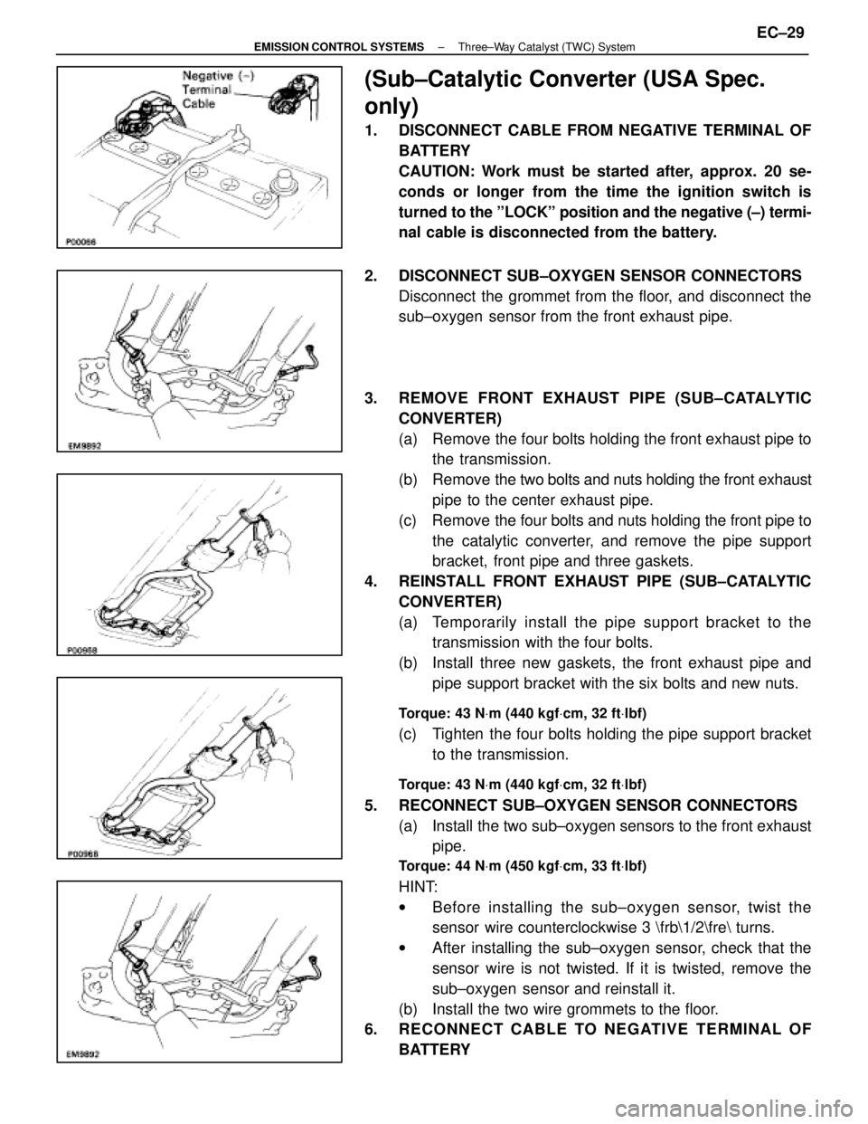
(Sub±Catalytic Converter (USA Spec.
only)
1. DISCONNECT CABLE FROM NEGATIVE TERMINAL OFBATTERY
CAUTION: Work must be started after, approx. 20 se-
conds or longer from the time the ignition switch is
turned to the ºLOCKº position and the negative (±) termi-
nal cable is disconnected from the battery.
2. DISCONNECT SUB±OXYGEN SENSOR CONNECTORS Disconnect the grommet from the floor, and disconnect the
sub±oxygen sensor from the front exhaust pipe.
3. REMOVE FRONT EXHAUST PIPE (SUB±CATALYTIC CONVERTER)
(a) Remove the four bolts holding the front exhaust pipe tothe transmission.
(b) Remove the two bolts and nuts holding the front exhaust
pipe to the center exhaust pipe.
(c) Remove the four bolts and nuts holding the front pipe to the catalytic converter, and remove the pipe support
bracket, front pipe and three gaskets.
4. REINSTALL FRONT EXHAUST PIPE (SUB±CATALYTIC CONVERTER)
(a) Temporarily install the pipe support bracket to thetransmission with the four bolts.
(b) Install three new gaskets, the front exhaust pipe and pipe support bracket with the six bolts and new nuts.
Torque: 43 N Vm (440 kgf Vcm, 32 ft Vlbf)
(c) Tighten the four bolts holding the pipe support bracket
to the transmission.
Torque: 43 N Vm (440 kgf Vcm, 32 ft Vlbf)
5. RECONNECT SUB±OXYGEN SENSOR CONNECTORS
(a) Install the two sub±oxygen sensors to the front exhaustpipe.
Torque: 44 N Vm (450 kgf Vcm, 33 ft Vlbf)
HINT:
w Before installing the s ub±oxygen sensor, twist the
sensor wire counterclockwise 3 \frb\1/2\fre turns.
w After installing the sub±oxygen sensor, check that the
sensor wire is not twisted. If it is twisted, remove the
sub±oxygen sensor and reinstall it.
(b) Install the two wire grommets to the floor.
6. RECONNECT CABLE TO NEGATIVE TERMINAL OF
BATTERY
±
EMISSION CONTROL SYSTEMS Three±Way Catalyst (TWC) SystemEC±29
WhereEverybodyKnowsYourName
Page 1331 of 4087
SERVICE SPECIFICATIONS
SERVICE DATA
VSVResistance30±34 �
for EVAP
VSVResistance33±39 �
for EGR
EGR valveResistance19.9±23.4 �
(CALIF. only)
TORQUE SPECIFICATIONS
Part tightenedNVmkgf Vcmft Vlbf
VSV for EGR X Air intake chamber (Exc. USA Spec.)1818513
EGR valve X Air intake chamber18185 13
Catalytic converter (Main) X Exhaust manifold62630 46
Catalytic converter (Main) X Front exhaust pipe43440 32
Front exhaust pipe support bracket X Transmission43440 32
Front exhaust pipe X Center exhaust pipe43440 32
Main oxygen sensor X Front exhaust pipe4445033
EC±30±
EMISSION CONTROL SYSTEMS Servuce Specifications
WhereEverybodyKnowsYourName
Page 1366 of 4087
THREE±WAY CATALYST (TWC) SYSTEM
DESCRIPTION
To reduce HC, CO and NOx emissions, they are oxidized, reduced and convert\
ed to nitrogen (N), carbon diox-
ide (CO) and water (HO) by the catalyst.
OPERATION
INSPECTION OF EXHAUST PIPE
ASSEMBLY
1. CHECK CONNECTIONS FOR LOOSENSESS ORDAMAGE
2. CHECK CLAMPS FOR WEAKNESS, C RACKS OR
DAMAGE
INSPECTION OF CATALYTIC
CONVERTER
CHECK FOR DENTS OR DAMAGE
If any part of the protector is damaged or dented to the extent
that is contacts the catalyst, repair or replace it.
INSPECTION OF HEAT INSULATOR
1. CHECK HEAT INSULATOR FOR DAMAGE
2. CHECK FOR ADEQUATE CLEARANCE BETWEENCATALYTIC CONVERTER AND HEAR INSULATOR
±
EMISSION CONTROL SYSTEMS Three±way Catalyst (TWC) SystemEC±17
WhereEverybodyKnowsYourName